Sargent 8200 Mortise Lock with BHW Trim Installation Instructions
Open the original PDF document
View PDFInstallation Instructions
ASSA ABLOY
BHW Trim for 8200 Mortise Locks
| TOC | Table of Contents | |
|---|---|---|
| 1 | Mortise Lock Handing Instructions | . 2 |
| 2 | Mortise Lock Function Changing Instructions | .3 |
| 3 | Mortise Lock Door Preparation & Installation | . 4 |
| 4 | BHW Trim Installation | . 6 |
| 5 | Turn-Piece Installation | . 8 |
| 6 | Coin-Turn Installation | . 8 |
QR Codes
To view the QR Code video clips within this document, download a free mobile app and scan the QR Code with your mobile device.
The complete video for Changing Lock Handing can be viewed on YouTube: https://youtu.be/3alaDIEST1k
The complete video for Changing Lock Functions can be viewed on YouTube: https://youtu.be/M_B9fDqlvQY
The complete video for Trim Installation can be viewed on YouTube: https://youtu.be/98mllgDncaE
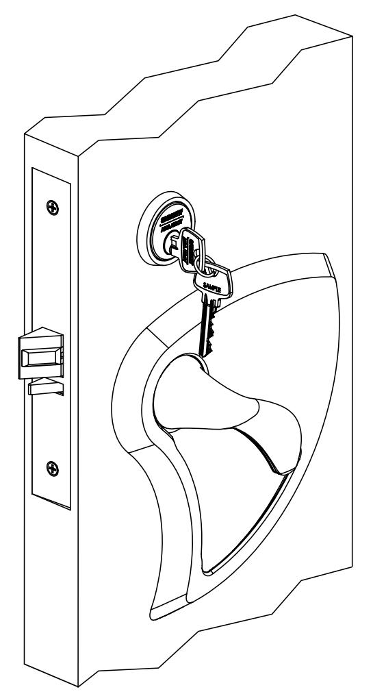
BHW Trim
8200 Mortise Lock
Installation Instructions

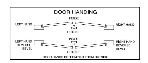
1 Mortise Lock Handing Instructions

NOTE:
RED SURFACE OF LOCKING PIECE MUST FACE SECURE SIDE OF DOOR.
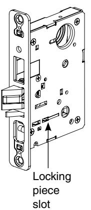
To rotate locking piece:
- 1. Position lockbody with red surface of locking piece visible.
- 2. Insert blade type screwdriver into locking piece slot to rotate locking piece.
- 3. Push locking piece toward back of lockbody and rotate 180° until RED surface shows on opposite side.
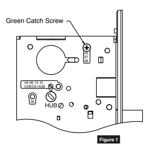
For 04, 06, 13 and 31 Functions:
- (a) Remove green catch screw.
- (b) Rotate hub to 45° position.
- (c) Rotate locking piece for required hand.
- (d) Face red surface to locked side of door.
- (e) Rotate hub to original 45° position (as shown on lockcase).
- (f) Reinstall green catch screw.
Red color indicates locked side of door or hold back side (91 and 92 Functions)
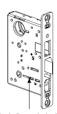
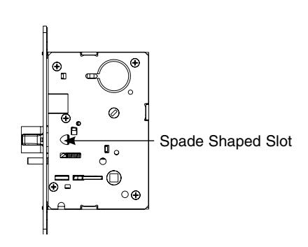
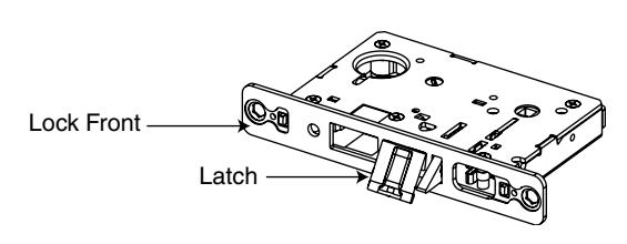
NOTE:
BEVELED SURFACE OF LATCH MUST FACE STRIKE. DEADLATCH IS SELF ADJUSTING.
To change hand of latch:
- 1. Insert screwdriver blade into the spade shaped slot.
- 2. Rotate screwdriver 90° to push latch out until back of latch clears lock front. Rotate latch 180°. Latch will re-enter lockbody.
NOTE:
LATCH CANNOT BE UNSCREWED.
Installation Instructions

2 Mortise Lock Function Changing Instructions

How to change function of lock:
Green catch screw must be located in following three (3) locations as designated on lock case to create desired function:
- 1. 05, 37 & 38 functions
- 2. 04, 06, 13 & 31 functions
- 3. 36 function
NOTE:
WHEN MOVING GREEN CATCH SCREW TO 04, 06, 13 & 31 FUNCTIONS, HUB POSITION MUST BE AT 45° AS SHOWN ON LOCKCASE (FIGURE 1).
Items needed to create each of the following functions:
| Function |
Outside
Lever |
Inside
Lever |
Trim One
Side Kit |
Outside
Cylinder |
Inside
Cylinder |
Thumb
Turn |
|---|---|---|---|---|---|---|
| 04 (F07) | X | X | X | |||
| 05 (F04) | X | X | X | X*** | ||
| 06 | X | X | X | |||
| 13 (F31) | X | X | ||||
| 31 | X | X | X | |||
| 36 | X | X | X | |||
| 37 (F05) | X | X | X | |||
| 38 (F32) | X | X | X | X |
#41 Cylinder is standard for both single & double cylinder functions for 1-3/4" thick door
NOTE:Trim-one-side functions always require an inside trim assembly which can be used on the inside or outside of the door (to order Trim one-side kit (for all trim except PT or FE) order part # 82-4611.
*** 130 KB thumb turn is used with rose trim only. Escutcheon trims requiring thumb turns must be preassembled at factory.
BHW Trim
8200 Mortise Lock
Installation Instructions

3 Mortise Lock Door Preparation & Installation

Important: Be sure to hand the lockbody before installing. See Section 1.
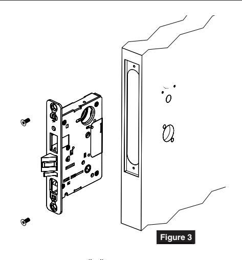
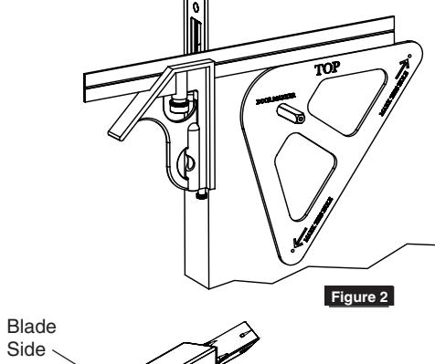
1. Insert mortise lock into door and fully tighten 1" lock mounting combination screws. (Figure 2)

- 2. Insert spindle into outside lockbody hub.
- 3. Slide trim door marker template over spindle.
NOTE:
MAKE SURE TEMPLATE IS ORIENTED CORRECTLY. (FIGURE 3)
- 4. Square template to edge of door. (Figure 3)
- 5. Mark two thru-bolt holes.
- 6. Repeat steps 2-5 for inside of door.
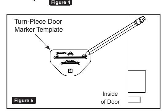
7. TURN-PIECE FUNCTIONS ONLY:
Insert turn-piece door marker spindle into lockbody on inside of door.
NOTE:
USE BLADE SIDE OF DOOR MARKER SPINDLE. (FIGURE 4)
- 8. TURN-PIECE FUNCTIONS ONLY: Slide turn-piece door marker over spindle.
- 9. TURN-PIECE FUNCTIONS ONLY: Mark three holes for turn-piece. (Figure 5)
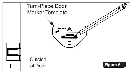
10. COIN-TURN FUNCTIONS ONLY:
Insert turn-piece marker spindle into lockbody on outside of door.
NOTE:
USE BLADE SIDE OF DOOR MARKER SPINDLE. (FIGURE 4)
11. COIN-TURN FUNCTIONS ONLY:
Slide turn-piece door marker template over spindle.
12. COIN-TURN FUNCTIONS ONLY:
Mark two holes for coin-turn. (Figure 6)
Installation Instructions

3 Mortise Lock Door Preparation & Installation
- 13. Remove lockbody from door.
- 14. Drill two (2) thru-bolt holes (9/16") halfway through one side of door.
- 15. Drill two (2) thru-bolt holes (9/16") through from opposite side of door.
NOTE:
DRILL THROUGH BOTH SIDES OF DOOR FOR BETTER ACCURACY.
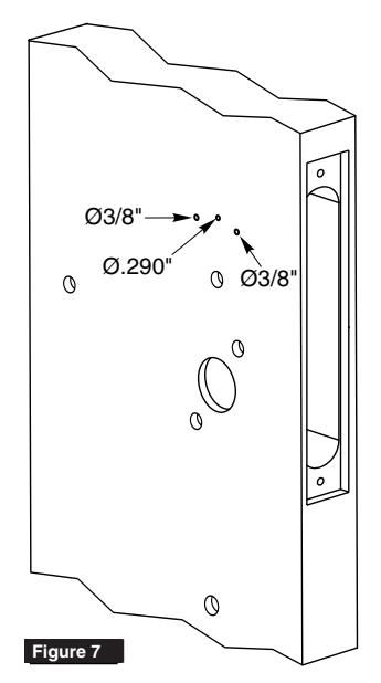
16. TURN-PIECE FUNCTIONS ONLY:
Drill one (1) middle hole (.290") and two (2) outer holes (3/8") halfway through door. (Figure 7)
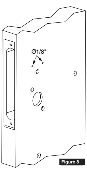
17. COIN-TURN FUNCTIONS ONLY:
Drill two (2) holes (1/8") halfway through door. (Figure 8)
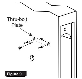
18. TURN-PIECE FUNCTIONS ONLY:
Install turn-piece thru-bolt plate using truss head screw. (Leave screw slightly loose.) (Figure 9)
NOTE:
THE THRU-BOLT PLATE IS INSTALLED INSIDE THE DOOR POCKET.
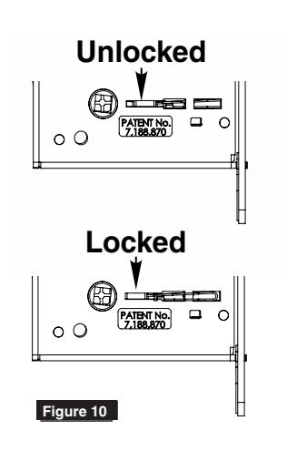
19. Insert mortise lockbody into door and loosely tighten 1" lock mounting combination screws.
NOTE:
MAKE SURE LOCK IS UNLOCKED. (FIGURE 10)
BHW Trim
8200 Mortise Lock
Installation Instructions

4 BHW Trim Installation

1. Install strike using 3/4" strike mounting screws.
NOTE:
STRIKE MUST BE ORIENTED WITH STRIKE LIP TOWARDS PULL SIDE OF DOOR. (FIGURE 11)

2. CYLINDER FUNCTIONS ONLY:
Slide cylinder(s) through spring, spacer and collar, threading into lockbody until cylinder face is flush with collar. (Figure 12)
NOTE:
PULL KEY SLIGHTLY OUT OF CYLINDER TO HELP THREAD INTO LOCKBODY.

CYLINDER MUST BE ORIENTED CORRECTLY. (FIGURE 13)

Tighten cylinder set screw. (Figure 14)
- 4. Fully tighten lock mounting screws.
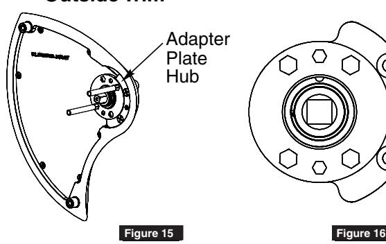
- 5. Thread adapter plate hub into lever and fully tighten. (Figure 15)
NOTE:
SPINDLE CAN BE USED TO HELP THREAD HUB INTO LEVER.
6. Align adapter plate hub with square hole in lever; keeping hub as tight as possible. (Figure 16)
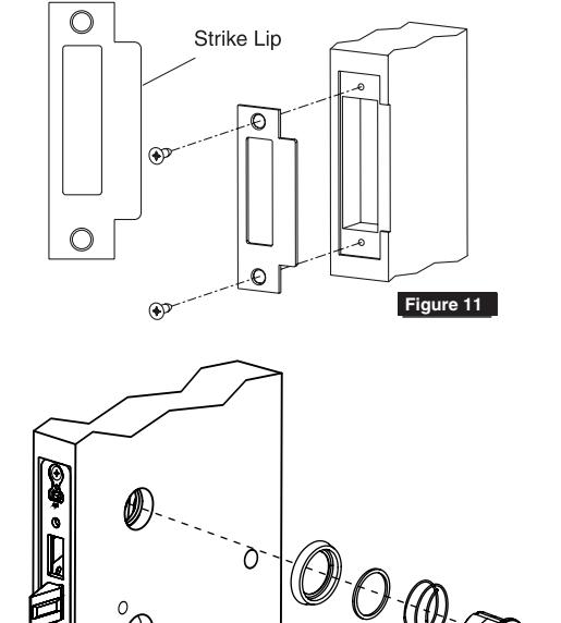
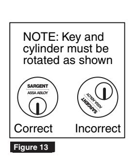
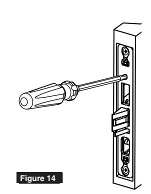
Figure 12
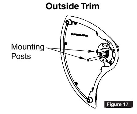
Outside Trim
8200 Mortise Lock
Installation Instructions

4 BHW Trim Installation
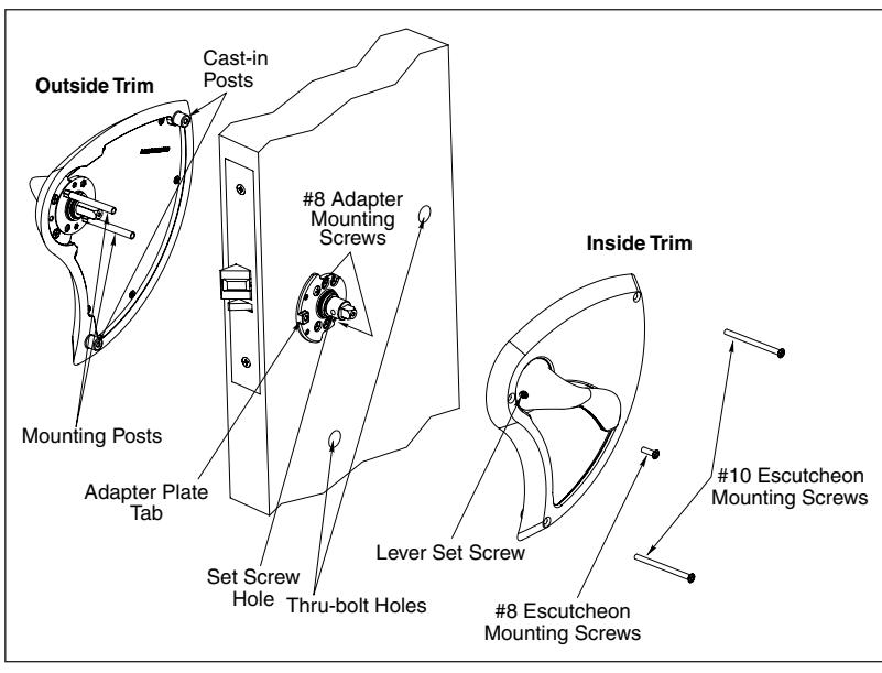
7. Insert spindle into outside trim assembly.

8. With lever in "up" position, align mounting posts on adapter plate with holes in lockbody and install outside trim assembly. (Figure 17)
NOTE:
AFTER OUTSIDE TRIM IS INSTALLED, ROTATE LEVER TO MAKE SURE SPINDLE IS ENGAGED IN LOCK. Figure 17

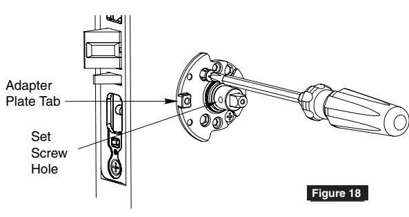
9. Slide inside adapter plate over spindle and install using two (2) adapter plate mounting screws. (Figure 18)
NOTE:
MAKE SURE ADAPTER PLATE TAB AND SET SCREW HOLE ARE FACING LOCK FRONT PRIOR TO INSTALLING SCREWS.

10. With lever in "up" position, install inside trim assembly.
NOTE:
AFTER TRIM IS INSTALLED, ROTATE LEVER TO MAKE SURE SPINDLE IS ENGAGED IN LOCK.

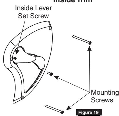
- 11. Tighten inside lever set screw. (Figure 19)
- 12. Install three (3) escutcheon mounting screws through inside escutcheon. (Figure 19)

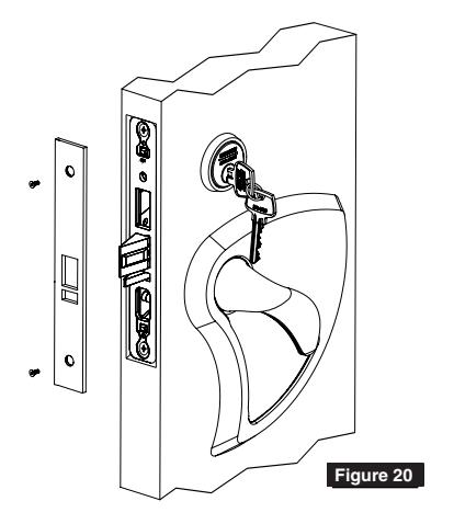
13. Install lock front using two (2) front screws. (Figure 20)
Inside Trim

5 Turn-Piece Installation
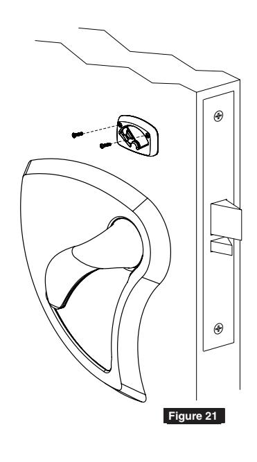
1. Install turn-piece loosely using two (2) turnpiece mounting screws. (Figure 21)
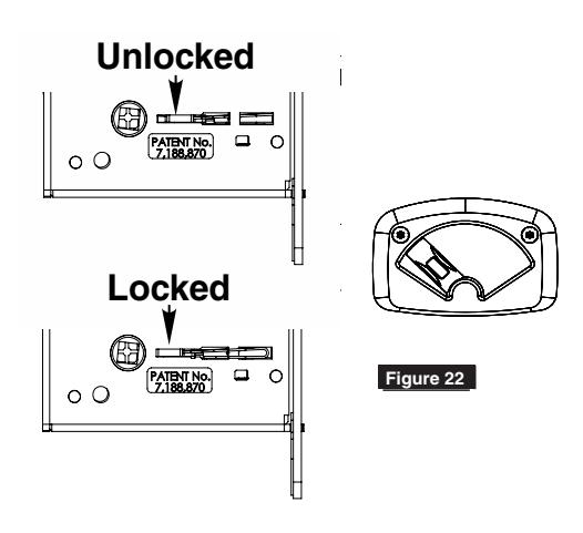
NOTE:
MAKE SURE LOCK IS UNLOCKED AND TURN-PIECE IS ROTATED AWAY FROM LATCH. (FIGURE 22)
2. Adjust location of turn-piece on door until turn-piece rotates easily, then fully tighten mounting screws.
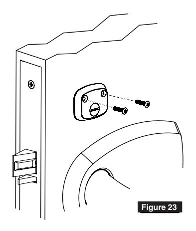
6 Coin-Turn Installation
1. Install coin-turn using two (2) surface mount screws. (Figure 23)
SARGENT Manufacturing Company 100 Sargent Drive New Haven, CT 06511 USA 800-727-5477
www.sargentlock.com
Founded in the early 1800s, SARGENT® is a market leader in locksets, cylinders, door closers, exit devices, electro-mechanical products and access control systems for new construction, renovation, and replacement applications. The company's customer base includes commercial construction, institutional, and industrial markets.
Copyright © 2017, Sargent Manufacturing Company, an ASSA ABLOY Group company. All rights reserved. Reproduction in whole or in part without the express written permission of Sargent Manufacturing Company is prohibited.