SX Template
Open the original PDF document
View PDFFB3
DO-IT-YOURSELF INSTRUCTIONS FOR INSTALLATION OF ENTRANCE LOCKS IN NEW DOORS OR THE REPLACEMENT OF EXISTING LOCKS
FOR USE ON DOORS 1-3/8" TO 2" (35mm~51mm) THICK
TOOLS REQUIRED FOR NEW INSTALLATION
1 phillips head screwdriver
1 2-1/8" (54mm) hole saw
1 1" (25.4mm) drill bit 1 13/64" (5mm) drill bit
1 chisel
FOLLOW ALL STEPS FOR REMODELING OR NEW CONSTRUCTION.
FOLLOW STEPS 3C,4C,5,6,7,8,9 and 10 FOR DO-IT-YOURSELF REPLACEMENT FOLLOWING REMOVAL OF EXISTING LOCK.
REPLACING EXISTING ENTRANCE LOCKS:
Before beginning, measure from center of lock to door edge in order to check length of backset on existing lock. The backset length of new lock is stated clearly on front of package. If backset size is the same, continue; otherwise, you'll have to replace lock with proper size backset.
TOOLS REQUIRED FOR REPLACEMENT INSTALLATION:
1 phillips head screwdriver ILLUSTRATIONS ARE SHOWN WITH ENTRANCE MODELS. INSTALLATION IS SAME FOR PRIVACY AND PASSAGE MODELS AS WELL.
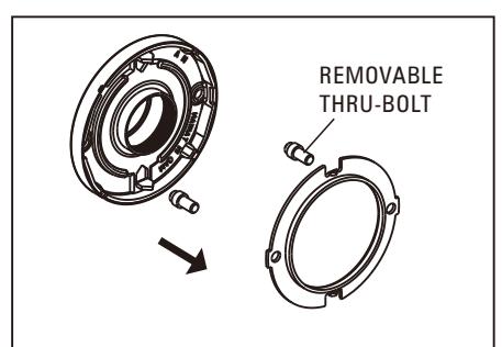
Optional thrubolts are provided and recommended for use on high frequency doors. Warranty voided if optional thrubolt are not installed.
INSTALLATION INSTRUCTIONS
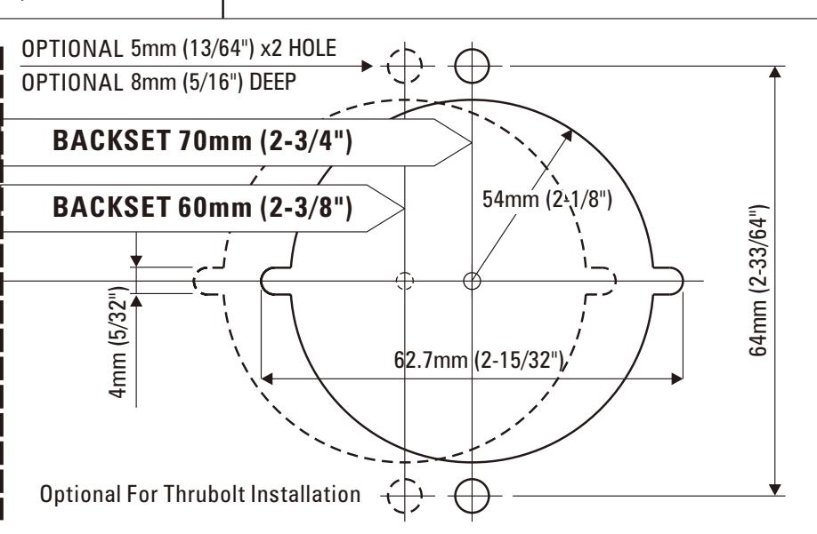
1. MARK DOOR MARK FOR MARK ONF HOLE 2-1/8" 1"(25.4mm) (54mm) HOLE IN DOOR EDGE
ON DOOR FACE. OPTIONAL: ALSO MARK TW0 H0LES13/64' (5mm), 5/16"(8mm) DEEP ON DOOR FACE
(914mm) from floor. Fold and apply template to edge of door and mark center of door edge as indicated on template. Mark center hole on door face through guide on template.
Start approximately 36"
(NOTE: Backset on door face must be same as backset of lock.)
2. DRILL HOLES
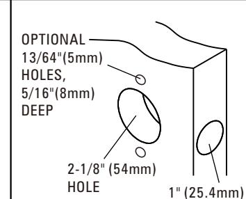
Drill 2-1/8" (54mm) hole through door face and two holes 13/64" (5mm), Drill 1" (25.4 mm) hole in center of door edge for latch. OPTIONAL:
5/16"(8mm) deep as marked for lockset. It is recommended that holes be drilled from both sides to prevent splitting.
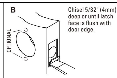
3. INSTALL LATCH
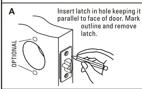
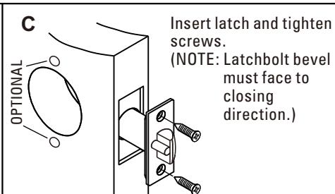
(NOTE: Latchbolt bevel must face to closing
direction.)
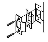
4. INSTALL STRIKE
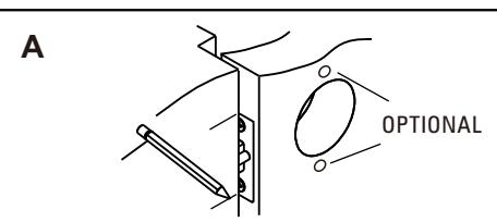
Close door until latchbolt touches jamb to locate strike in jamb and center line of strike. Open door and extend line from mark to door stop. Measure one half of door thickness from door stop and vertically mark drill point center
Drill 1" (25.4mm) hole 1/2" (12.7mm) deep in door jamb on drill point for strike
CAUTION: To ensure proper lockset function. Hole in jamb must be drilled a full 1/2" (12.7mm) deep.
Cut out jamb 9/64" (3.6mm) deep for strike. Tighten screws.
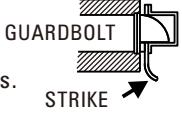
Guardbolt stops against strike, as illustrated, preventing forcing when door is closed. Adjustable tang on strike permits bending in or out to
eliminate too loose fit between door and door stop.
FB3 FB3
FB3 FB3
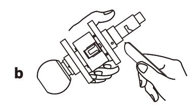
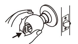
5. REMOVE INSIDE KNOB
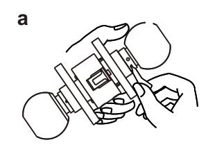
Use nail end of wrench provided to depress inside knob catch in hole of inside sleeve collar and slide knob off spindle.
Please use the disassembled tools to loose inside rose, then draw it out.
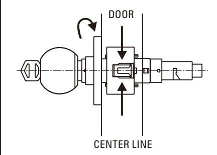
6. ADJUST OUTSIDE ROSE
Adjust lock to fit door thickness by rotating outside rose. Lock will fit all doors 1-3/8" to 2" (35mm~51mm) thick.
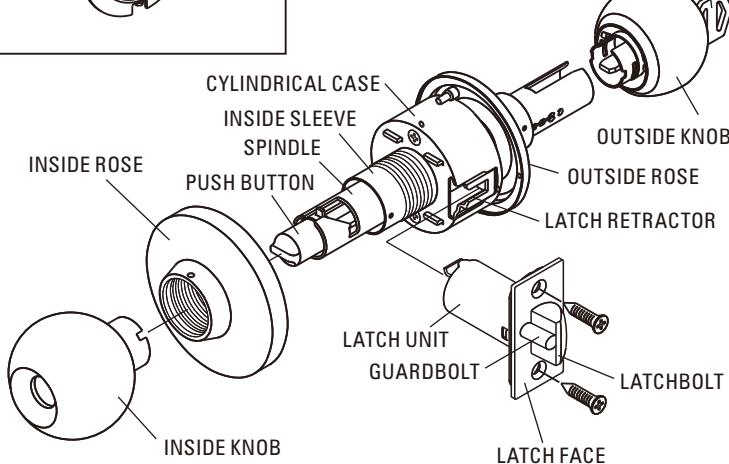
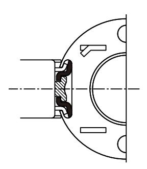
7. INSTALL LOCK
Latch unit must be in place before installing lock. Be sure lock housing engages with latch prongs and retractor interlocks with latch tail.
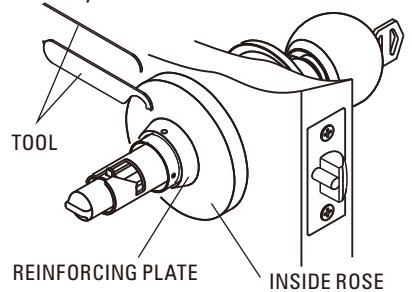
8. INSTALL INSIDE ROSE
Insert inside rose and reinforcing plate into hole, turn the reinforcing plate clockwise until the plate engaged with the hole, make sure the two rose grooves face to door hole, then use tool (either type of tool is attached) tighten inside rose securely.
9. REPLACE KNOB
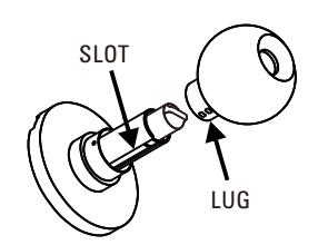
IMPORTANT-Align lug on knob with narrow slot on side of spindle and push knob all the way in until knob catch clicks into slot on knob.
Otherwise knob will jamb on shaft.
10. RIGHT KEY HOLE POSITION
Upon installation of the lock, it may happen that key hole faces upward or downward as shown in the following drawing.
It is advisable to correct all key hole to be facing downward.
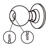
DOWNWARD CORRECT
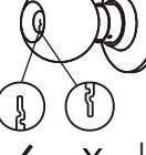
UPWARD INCORRECT
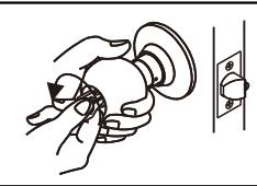
11. IN ORDER TO ADJUST THE ABNORMAL STATE OF THE KEY HOLE FACING UPWARD, THE KNOB MUST BE PULLED OUT AND INSTALLED AGAIN. THE METHOD OF INSTALLATION IS DESCRIBED AS BELOW.
- First turn the knob clockwise until the knob catch appears in the small hole.
- With the other hand, turn the key counterclockwise within the limit of 30° ~90°
Using a small nail C to press the knob catch and pull the
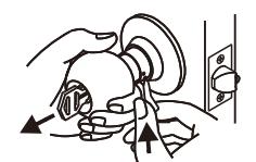
Install again according to the correct direction.
TEMPLATE Fit here on door edge 45 51 40 35 2" 1-3/4" 1-9/16" 1-3/8" Mark 1" (25.4mm) hole at center of door edge.