STI Installation Torque Catalog
Open the original PDF document
View PDFWhat is Torque?
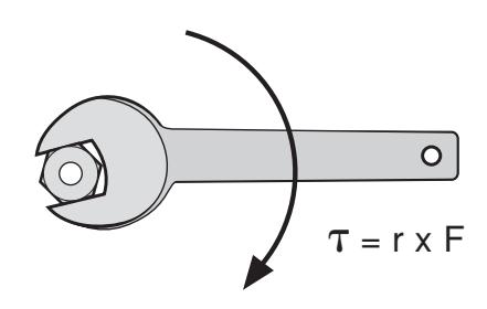
Torque is the tendency of a force to rotate an object about an axis. Just as a force is a push or pull, a torque can be thought of as a twist. Loosely speaking, torque is a measure of the turning force on an object such as a bolt. The unit of measure is generally expressed in foot pounds or inch pounds
The formula for torque is:
= r x F
where:
is the torque
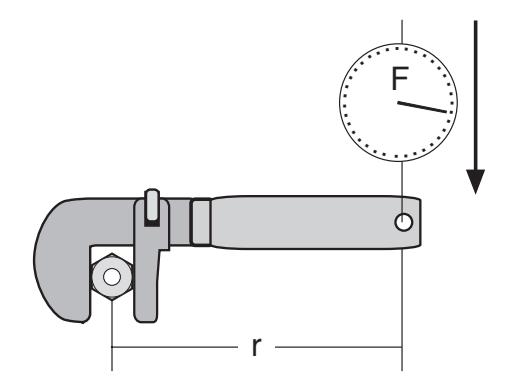
r = the length of the lever arm
F = the force
Properly fastened threaded products achieve their holding power from the tension (or torque) that is derived from the mating of the external and internal threads subject to the elastic limit of the material.
What torque to apply is a generally asked question, but the answer depends on the variables of material, threads' class of fit, method of thread manufacture, and thread lubrication - if any.
Table 3 is offered as the suggested maximum torque values for threaded products. The table is only a guide. Actual tests were conducted on dry, or near dry, products. Mating parts were wiped clean.
| Table 3 – Strength Characteristics | |||||||
|---|---|---|---|---|---|---|---|
|
Bolt
Size |
18-8
SS |
Brass |
Silicon
Bronze |
Aluminum
2024-T4 |
316
SS |
Monel | Nylon* |
| In. Lbs. | In. Lbs. | In. Lbs. | In. Lbs. | In. Lbs. | In. Lbs. | In. Lbs. | |
| 2-56 | 2.5 | 2.0 | 2.3 | 1.4 | 2.6 | 2.5 | .44 |
| 2-64 | 3.0 | 2.5 | 8.0 | 1.7 | 3.2 | 3.1 | |
| 3-48 | 3.9 | 3.2 | 3.6 | 2.1 | 4.0 | 4.0 | |
| 3-56 | 4.4 | 3.6 | 4.1 | 2.4 | 4.6 | 4.5 | |
| 4-40 | 5.2 | 4.3 | 4.8 | 2.9 | 5.5 | 5.3 | 1.19 |
| 4-48 | 6.6 | 5.4 | 6.1 | 3.6 | 6.9 | 6.7 | |
| 5-40 | 7.7 | 6.3 | 7.1 | 4.2 | 8.1 | 7.8 | |
| 5-44 | 9.4 | 7.7 | 8.7 | 5.1 | 9.8 | 9.6 | |
| 6-32 | 9.6 | 7.9 | 8.9 | 5.3 | 10.1 | 9.8 | 2.14 |
| 6-40 | 12.1 | 9.9 | 11.2 | 6.6 | 12.7 | 12.3 | |
| 8-32 | 19.8 | 16.2 | 18.4 | 10.8 | 20.7 | 20.2 | 4.3 |
| 8-36 | 22.0 | 18.0 | 20.4 | 12.0 | 23.0 | 22.4 | |
| 10-24 | 22.8 | 18.6 | 21.2 | 13.8 | 23.8 | 25.9 | 6.61 |
| 10-32 | 31.7 | 25.9 | 29.3 | 19.2 | 33.1 | 34.9 | 8.2 |
| 1/4"-20 | 75.2 | 61.5 | 68.8 | 45.6 | 78.8 | 85.3 | 16.0 |
| 1/4"-28 | 94.0 | 77.0 | 87.0 | 57.0 | 99.0 | 106.0 | 20.8 |
| 5/16"-18 | 132 | 107 | 123 | 80 | 138 | 149 | 34.9 |
| 5/16"-24 | 142 | 116 | 131 | 86 | 147 | 160 | |
| 3/8"-16 | 236 | 192 | 219 | 143 | 247 | 266 | |
| 3/8"-24 | 259 | 212 | 240 | 157 | 271 | 294 | |
| 7/16"-14 | 376 | 317 | 349 | 228 | 393 | 427 | |
| 7/16"-20 | 400 | 327 | 371 | 242 | 418 | 451 | |
| 1/2"-13 | 517 | 422 | 480 | 313 | 542 | 584 | |
| 1/2"-20 | 541 | 443 | 502 | 328 | 565 | 613 | |
| 9/16"-12 | 682 | 558 | 632 | 413 | 713 | 774 | |
| 9/16"-18 | 752 | 615 | 397 | 456 | 787 | 855 | |
| 5/8"-11 | 1110 | 907 | 1030 | 715 | 1160 | 1330 | |
| 5/8"-18 | 1244 | 1016 | 1154 | 798 | 1301 | 1482 | |
| 3/4"-10 | 1530 | 1249 | 1416 | 980 | 1582 | 1832 | |
| 3/4"-16 | 1490 | 1220 | 1382 | 958 | 1558 | 1790 | |
| 7/8"-9 | 2328 | 1905 | 2140 | 1495 | 2430 | 2775 | |
| 7/8"-14 | 2318 | 1895 | 2130 | 1490 | 2420 | 2755 | |
| 1"-8 | 3440 | 2815 | 3185 | 2205 | 3595 | 4130 | |
| 1"-14 | 3110 | 2545 | 2885 | 1995 | 3250 | 3730 | |
| FtLbs. | FtLbs. | FtLbs. | FtLbs. | FtLbs. | FtLbs. | ||
| 1-1/8"-7 | 413 | 337 | 383 | 265 | 432 | 499 | |
| 1-1/8"-12 | 390 | 318 | 361 | 251 | 408 | 470 | |
| 1-1/4"-7 | 523 | 428 | 485 | 336 | 546 | 627 | |
| 1-1/4"-12 | 480 | 394 | 447 | 308 | 504 | 575 | |
| 1-1/2"-6 | 888 | 727 | 822 | 570 | 930 | 1064 | |
| 1-1/2"-12 | 703 | 575 | 651 | 450 | 732 | 840 | |
* Nylon figures are breading torque, all others represent safe working torque.
The 3/8" diameter and under metal products were roll-threaded and, where size range permitted, were made on automatic bolt making equipment.
Enclosure Installation Considerations - Torque Cont. • Cutting & Drilling
Torque Formula Illustrations
Methods For Making Holes And Cutouts In Non-Metallic Enclosures
Drilling of composite fiberglass material has been difficult and, for some, a mystery. The ability to accurately drill holes in composite fiberglass material has been the subject matter of numerous articles and how to demonstrations. There are several types of machining operations that can be performed on composites such as turning, drilling, routing, trimming, sanding, and milling. Most of these operations are similar to metal removal techniques but there are some differences that need to be addressed in order to make clean, high quality holes and cutouts in composites.
Delaminating of the outer surface and glass fibers directly below the surface are the main failure modes noticed when holes or cutouts are drilled or cutout improperly. Most times excessive edge chipping around the perimeter of the cutout or hole is due to improper tools used and methods applied. Other times excessive fiber pulls or attached fibers not sheared off during the cutting or turning process can also cause delamination failure from the tearing action during material removal. Improper tools used and/or methods are also a culprit of this failure mode. All these can lead to downstream assembly problems, functionality problems, and become aesthetically unappealing if taken to the extreme.
The most common source of failure mode when making holes in an enclosure is a dull cutting tool. Dull tools tend to rip or tear the material rather than cutting or shearing the material and glass fibers. The main culprit for tools becoming dull is glass fibers embedded in the material. These glass fibers are very abrasive and can cause a tool to become dull very quickly. A little planning and understanding of the proper methods to machining composites up front can make all the difference in the final outcome of the operation.
Figure A shows delamination of the surface of the part at the drill entrance.
(A) (B)
Figure B shows similar delamination just prior to drill exit.