STB Microtechniques Finger Lock Installer Manual
Open the original PDF document
View PDFFingerlock
Installer manual

FL3500
| FL3500 | FL-MAIe-2602-JB | |
|---|---|---|
| Crée le 27.05.02 | Par: JMB | |
| Installer manual | Contrôlé le: | |
| Modifié le | Par: |
Contents
| Table | 1 | |||
|---|---|---|---|---|
| 1. | Introduction | 2 | ||
| 2. | Components | |||
| 3. | Mounting of external housing | 2 | ||
| 4. | Mounting of internal housing | 3 | ||
| 5. | Connections | 3 | ||
| 6. | Software installation | 4 | ||
| 7. | Configuration | 5 | ||
| 7.1. | Serial port | 5 | ||
| 7.2. | Date and time setting | 5 | ||
| 7.3. | Installer menu | 5 | ||
| 7.4. | Master code | 6 | ||
| 7.5. | Hardware setting | 6 | ||
| 7.6. | Security level | 7 | ||
| 7.7. | Power supply and remote connection | 7 | ||
| 7.8. | Managers | 8 | ||
| 7.9. | Users | 8 | ||
| 7.10. | Stand-alone mode | 9 | ||
| 7.11. | Number of locks and holding time | 9 | ||
| 7.12. | Wrong trials penalties | 10 | ||
| 7.13. | Timelock feature | 10 | ||
| 7.14. | Time Delay feature | 11 | ||
| 7.15. | Installation summary | 12 | ||
| 7.16. | Timelock and Time delay configuration | 13 | ||
| 7.17. | First manager enrollment | 14 | ||
| 8. | Keypad | 15 | ||
| 9. | Maintenance | |||
| 10. |
Tips
16 |
|||
1. Introduction
Installation of the FL3500 lock requires two distinct steps
- a) Hardware installation
- b) Software installation and parameter setting
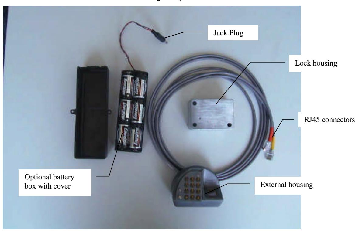
2. Components
The FL3500 lock set includes the following components:
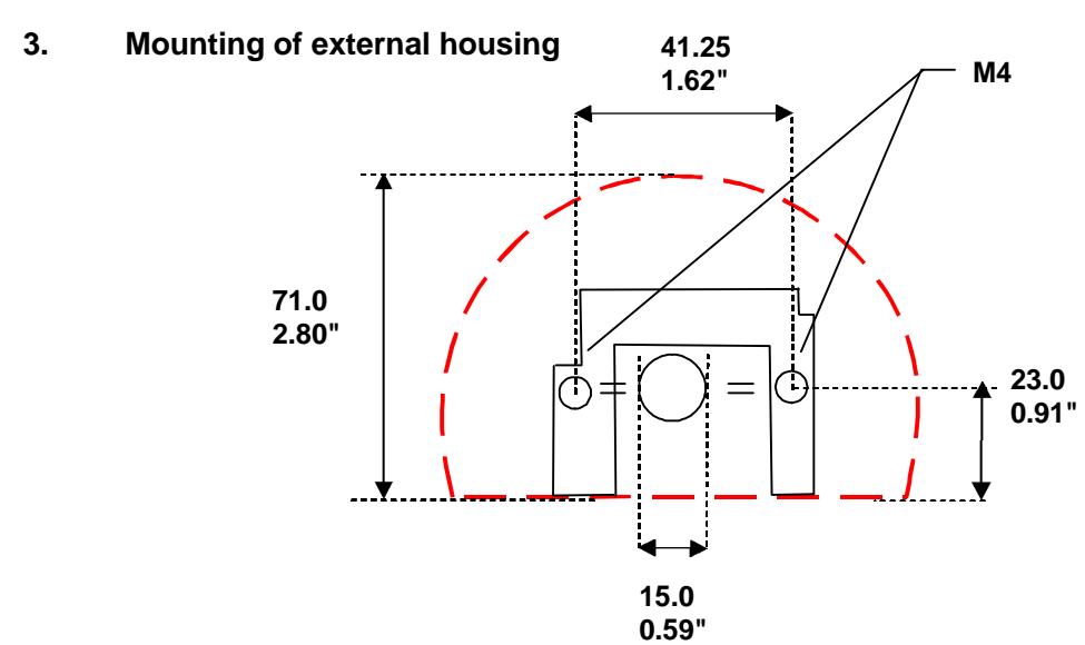

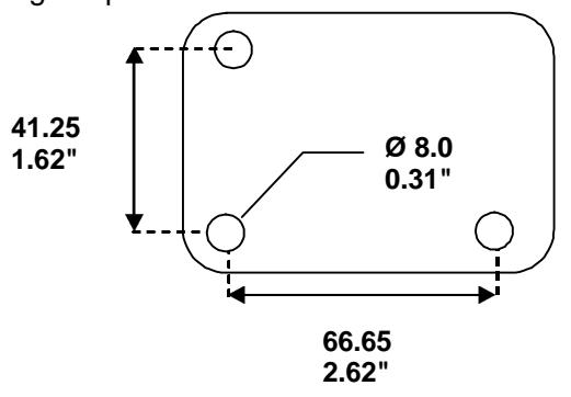
- Prepare the door according to the following hole pattern
- Mount the base plate onto the door with the two chamfer-headed screws (supplied). The mounting pattern is identical to any standard mechanical lock.
- Thread the 2 cables through the door. Do not exert strong traction from the inside! Always keep slack!

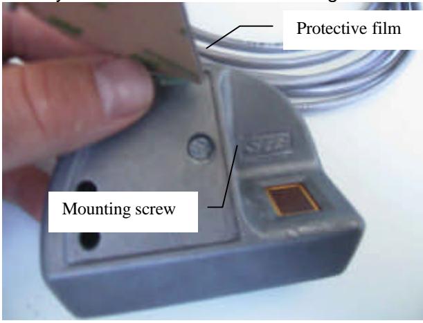
Note: Do not remove the protective film of the keypad as long as the lock has not been successfully tested
4. Mounting of internal housing
• Lock mounting footprint is the same as most locks available on the market.
Note: If available space does not allow mounting the lock as one single unit, the electronic box can be mounted separately and connected to the mechanical portion. This design can also be used for security reasons. (For additional information contact STB or your nearest dealer)
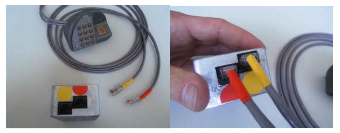
5. Connections
After mounting both external and internal housings:
• Connect the two RJ45 cables coming through the door to the corresponding plugs (orange to orange) on the side of the internal housing:
• Insert the jack plug, linked either to the external power supply or to the battery box into the lock housing (admitted tension 5-12V, a higher tension damages the lock)
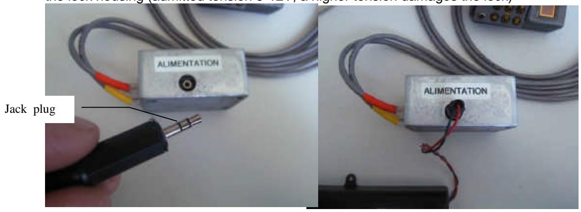
The lock is ready to be configured.
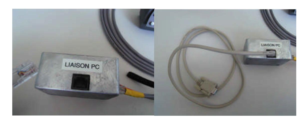
Plug the DB9/RJ45 respectively into your PC serial port (COM) and into the free connector of the lock
6. Software installation
In order to set the lock parameters and enroll the first manager, install the FL3500 software on the PC that will then be used in connection with the lock. Proceed as follows:
- Insert the CD or floppy disk into the PC
- Select setup.exe and double-click on it.
- Follow the instructions on your PC screen
7. Lock configuration
When shipped from the factory, the FL3500 Lock is in "installation mode". This means that the only menu that is available in the software is the installation menu. It is used to set the parameters according to the customer's choices.
7.1. Serial port selection
Start the software by double-clicking on the FL3500 icon The window below appears on the screen:

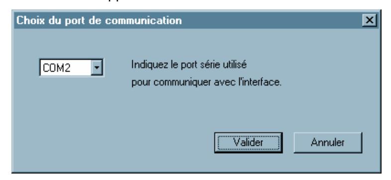
Select the serial port used on the PC and confirm (click on <NEXT>)
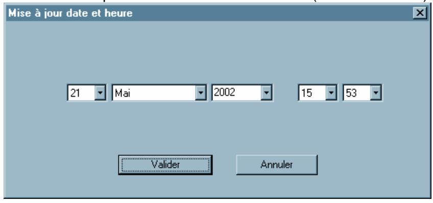
7.2. Date and time setting
Note : Enter date and time, then confirm. The accuracy of these parameters is essential for the validity of audit trail records.
7.3. Installer menu
In the main window, select the "INSTALLER" menu (other buttons are disabled, except the "FILE" menu for exiting the FL3500 Software)
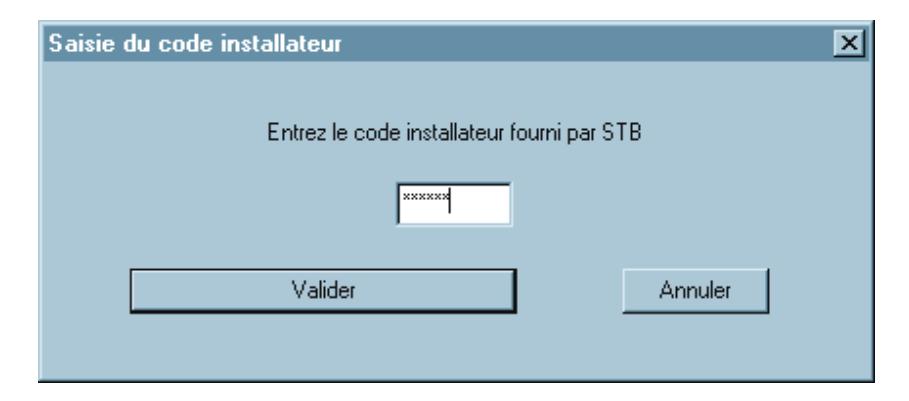
7.4. Master code
Enter the Master code supplied by STB to start the installation process. Keep this Master code in a safe place, as it is necessary to gain access to the maintenance menu and modify parameters and settings.
7.5. Hardware setting
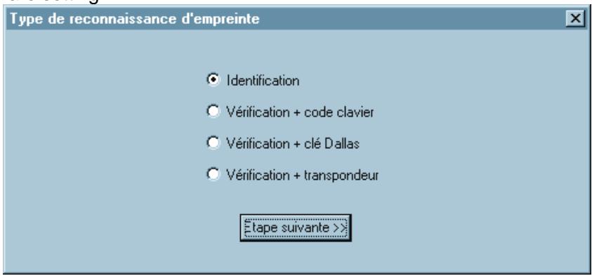
Based on your lock configuration, select the required option:
- - FL3510 → Identification.
- FL3520 → Verification + combination.
- FL3530 → Verification + Dallas key.
- FL3540 → Verification + contactless card.
Then click on <Next>
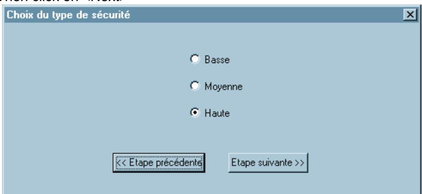
7.6. Security level
Select the required level. This level only modifies the acceptance threshold of the fingerprint; it has no other influence on the security features of the lock. (For further information about this option refer to the "FL3500 Technical description" manual)
Note: To modify the selected parameters at any time during installation, click on <PREVIOUS>.
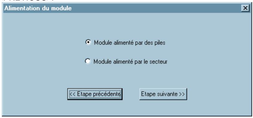
7.7. Power supply and remote connection
Select the power source, battery or network, <NEXT>.
Note: External power supply (network) must have a tension between 5 and 12V. Any tension above 16V would damage the lock.
If battery option has been selected, the following window appears:
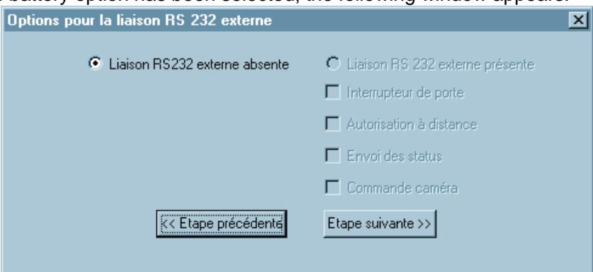
Selection of a connection to a remote computer through a serial line is not possible <NEXT>.
If "NETWORK" has been selected, the same window appears, but the selection of various options is possible when a connection to a remote computer through a serial line is present.
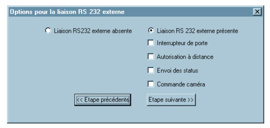
Select required options <NEXT>.
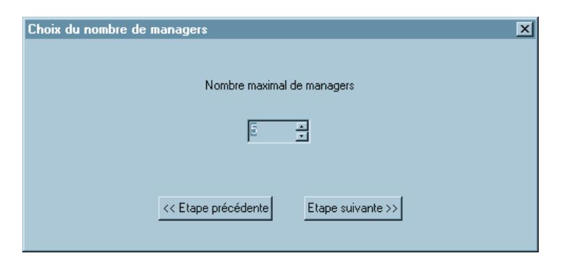
7.8. Managers
The maximum number of managers can be set between 1 and 5. <NEXT>.
Note: It is recommended to have at least two enrolled managers. Unlike combination locks, if a manager is not in a position to operate the lock, he cannot give his code or key to his substitute.
A manager can enroll and delete users and access the FL3500 software to modify some lock parameters after its installation. He can only access the MANAGER menu.
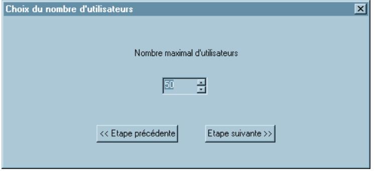
7.9. Users
The maximum number of users can be set between 1 and 50. <NEXT>.
Note: The more users are enrolled in the lock, the longer it will take to recognize a fingerprint, especially if the lock is configured in i dentification mode.
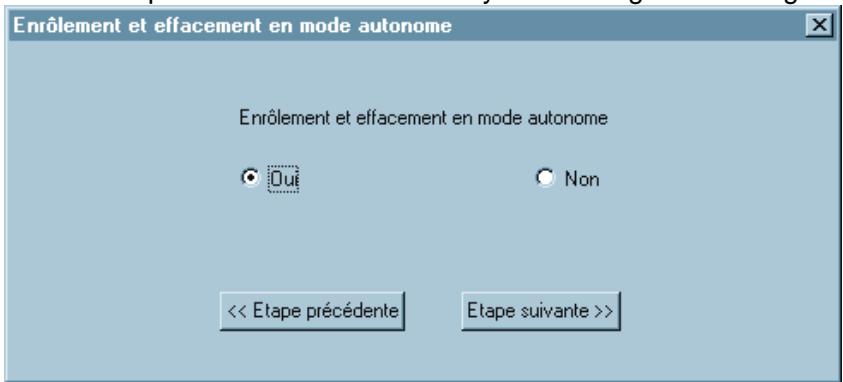
7.10. Stand-alone mode
If "Enroll and delete in stand-alone mode" is selected, any manager can give access or cancel users without using a PC.
Note: This option can be modified at any time through the manager menu
7.11. Number of locks and holding time
In order to have an alarm finger, select 2 locks and connect the second Lock signal to an output relay. The lock sends a 9V tension to operate the solenoid.
Select the number of locks <NEXT>.
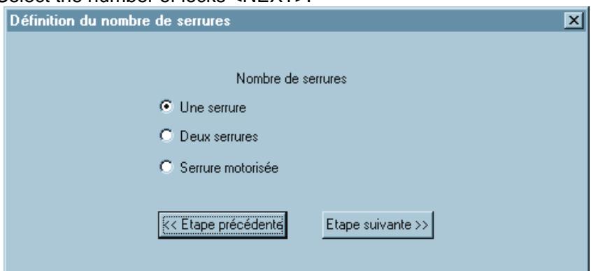
For each lock: Time range from 1 to 10 seconds (usual setting is 5 seconds) <NEXT>.
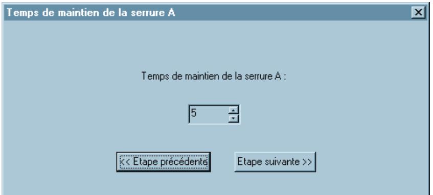
For a motor lock, set opening and holding time <NEXT>.

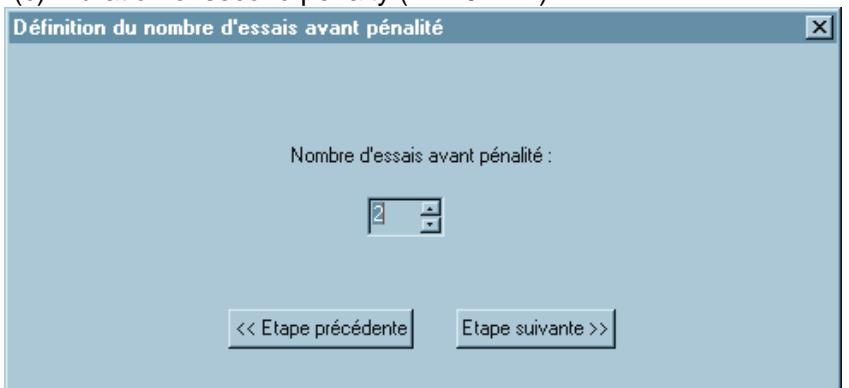
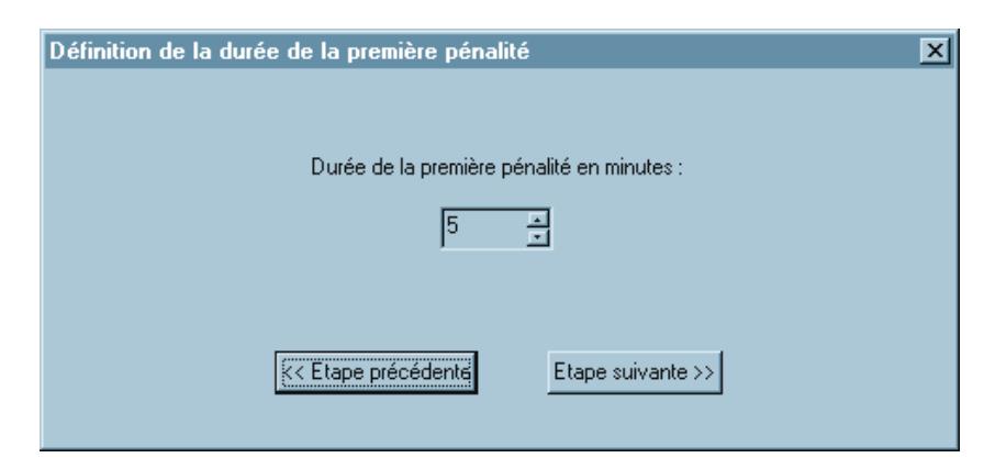
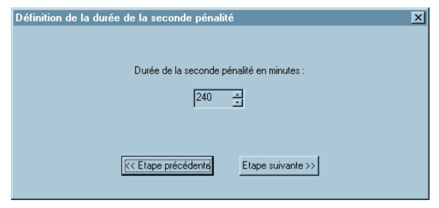
7.12. Wrong trials penalties
There are three parameters that need to be set
- (a) Number of wrong trials before first penalty (1-10)
- (b) Duration of first penalty (1-240 min.)
- (c) Duration of second penalty (1-240 min.)
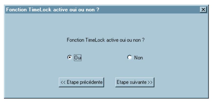
7.13. Timelock feature
This feature will give the manager access to the annual and weekly program, to the shift programs and the Timelock exceptions. This window only allows enabling the Timelock feature; its configuration has to be done at the end of the installation process. (see page 13).
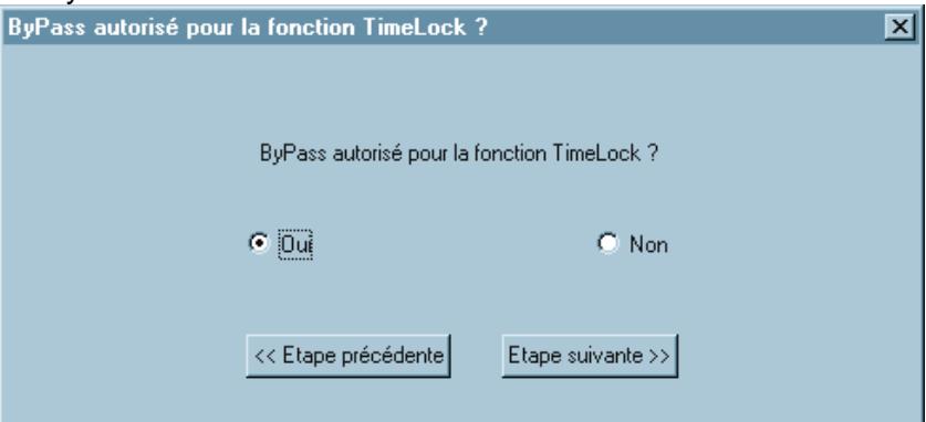
Some countries require a Timelock override for the managers. This feature is usually not activated.
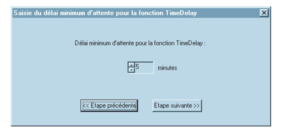
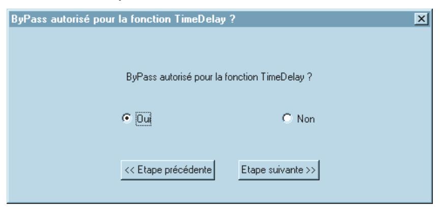
7.14. Time Delay feature
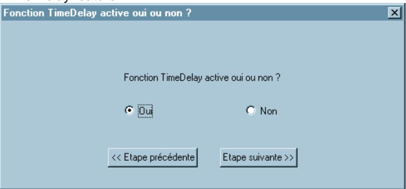
After enabling the Time delay, it is possible to set a minimal delay period, as local regulations may vary. This minimal delay cannot be modified by the manager. He can then set the actual delay between this threshold and 19 minutes.
The managers can be allowed to bypass the Time delay, but only before the delay has been started by a user.
7.15. Installation summary
When all parameters are set, a summary of the lock configuration appears on the screen. At that point, it is still possible to make modifications.
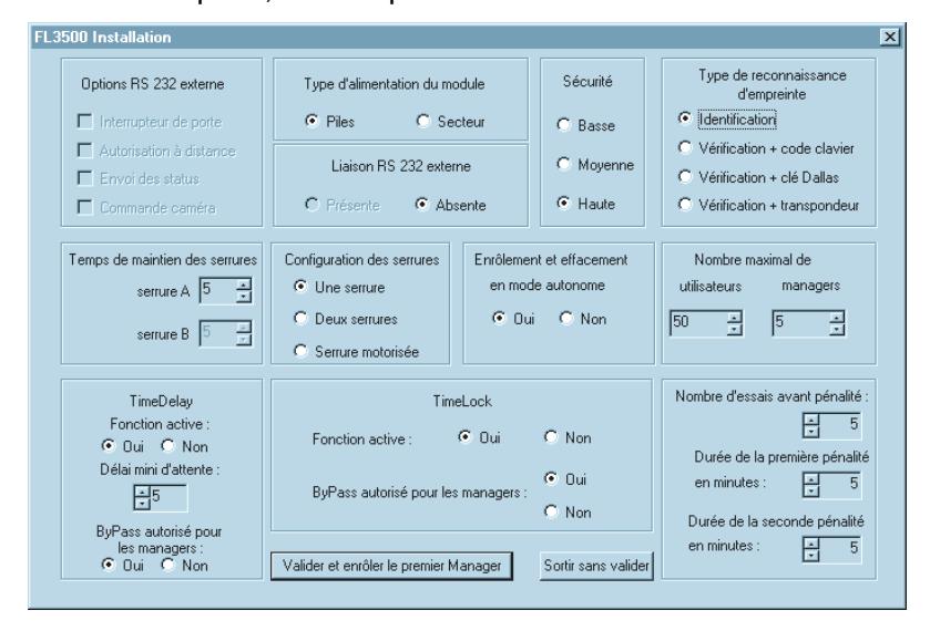
If the configuration is correct, clicking on <Accept and enroll first manager> will display either
- − The Timelock configuration windows (if the Timelock feature is enabled), or
- − The first manager enrollment window

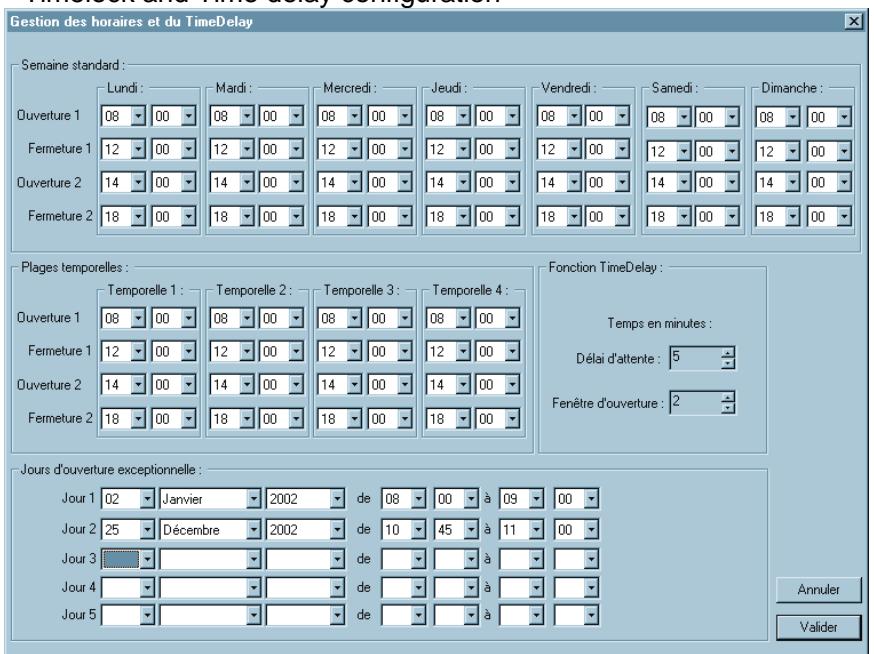
a) Standard week
This program is the frame within which any other time schedules have to be included. For example, a shift program cannot schedule a longer opening than the one set in the standard week.
b) Shift programs
These programs are designed for people who do not work full time or are only present in the branch for a limited period of the day.
-
c) Timelock exceptions
- In order not to have to modify the standard weekly program in case of special events, such as weekend or late opening, five exceptions can be programmed. They specify the date, and the starting and ending time of the special event. Once an event is over, a new one can be reprogrammed.
- d) Time delay
Delay period: see §6.14
Opening window can be set from 1 to 99 minutes
7.17. First manager enrollment
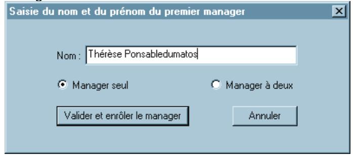
- Enter manager's name
- Choose single or dual opening
- <Accept and enroll first manager>
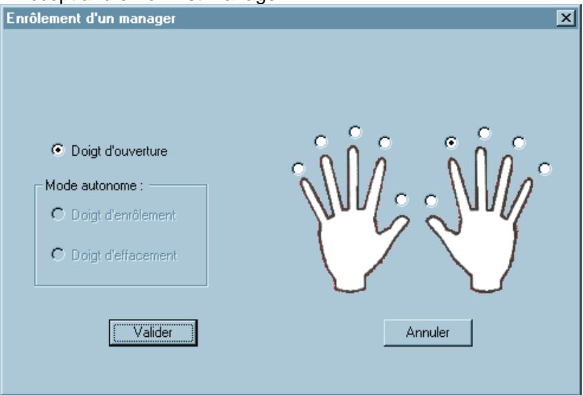
- Select the opening finger
- Follow the enrollment instructions depending on the lock hardware configuration.
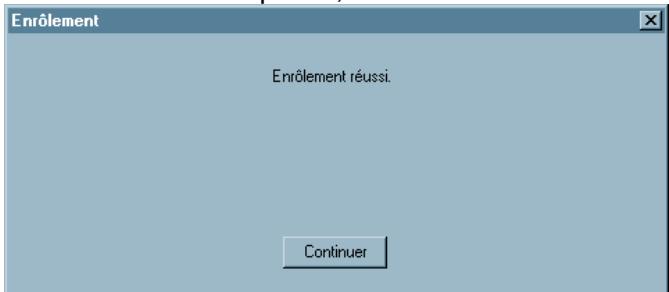
- Once full enrollment is completed, the "successful enrollment" window appears
Note: If the "dual opening" option has been selected, a window will appear requiring the enrollment of a second manager. The enrollment procedure is the same as for the first one.
In both cases, if the enrollment is not successful (bad positioning of the finger or insufficient template quality), the following message will be displayed:
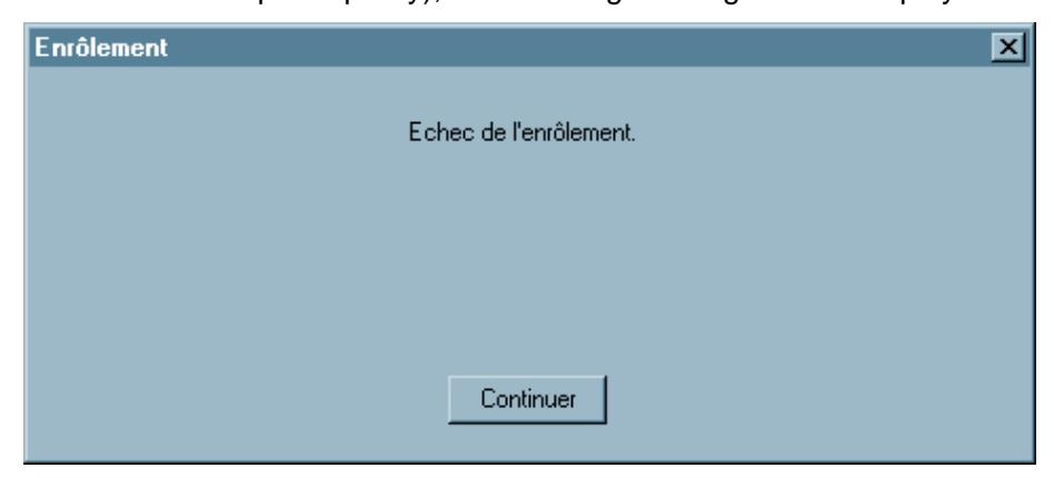
The enrollment procedure must be started again. If enrollment is not completed after 2 trials with the same finger, try an alternate finger.
After successful enrollment of the first manager(s), the time setting window will be displayed again. Check and confirm the date and time.
Installation is completed. It is now possible to reach the manager menu to enrol users and/or more managers with required privileges. These procedures are described in "FL3500 Manager Instructions"
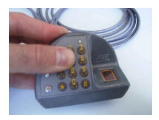
8. Keypad
When the lock has been successfully tested, the keypad still has to be glued on the external housing.
- Carefully lift the keypad (the flat cable is a sensitive part of the lock) Remove the protective film
- Strongly apply the keypad to the housing. Apply pressure for at least one minute
9. Maintenance mode
All installation parameters can be modified through the maintenance menu.
Gaining access to the menu requires both a valid manager's fingerprint and the Master code.
Installer manual FL3500
10. Tips for trouble-free usage
00
Do install the lock according to supplied manufacturer's directions.
Do test the function of your new lock at least three times with the door locked open.
Do install new power cells at least once a year.
Do not test your new lock by closing and locking the door.
Do not expose your new lock to severe cold, heat or humidity.
Do not attempt repairs or alterations to your new lock.
Do not install batteries that are old, showing sign of "salting" or are the wrong brand or type.
Do not guess ; when there is a doubt about your lock's function, call a professional safe and vault technician.
Do not lock a chest or vault when the lock shows a low battery or system default (orange or red LED blinking during opening)