SOSS Door Hardware Invisible Hinges Installation Instructions
Open the original PDF document
View PDFIMPORTANT
Use only Porter-Cable Template Guide Bushing #42024 (Lock Face Routing) and #42237 (Lock Nut) to assure the following guide bushing dimensions: 21/32" I.D., 3/4" O.D., 9/16" distance past base.
To avoid installation problems, we recommend you do a practice installation on the same type of wood before using the template on your application. This practice will help ensure proper installation, and reveal any potential difficulties with the routing equipment and/or tools before using the template on your finished project.
SAFETY
Protective eyewear should be worn by anyone operating equipment used in the installation of SOSS Invisible Hinges, as should those in the area where the work is being performed. For safety, if you are not using the recommended Amana Tool Router Bits as described in Table B, use router bits with 1/2" diameter shanks only.
To mount SOSS Invisible Hinges using the hinge router guide template, you will need the following:
- 1 Extra long router bits (See table "B") 4 Measuring scale, ruler or spacing sticks
- 2 Template guide bushing and locknut 5 Electric drill or brace
- 3 Hinge installation template package 6 Selection of spade drills or wood bits
FIGURE 1
References the various components of the hinge router guide template. Become familiar with this terminology as it will be used throughout these instructions.
FIGURE 1
Recommended Spacing of SOSS Invisible
Hinges (Refer to Figure 2)
Notice that the "center" hinge is not shown in the usual location near the middle of the door. The "center" hinge should be located one-half the distance from the center of the door to the center of the top hinge. This is to fortify the door against extra leverage extended on the top hinge.
On applications requiring more than four SOSS Invisible Hinges, a good rule of thumb is to place more SOSS Invisible Hinges in the upper half of the door than in the lower.
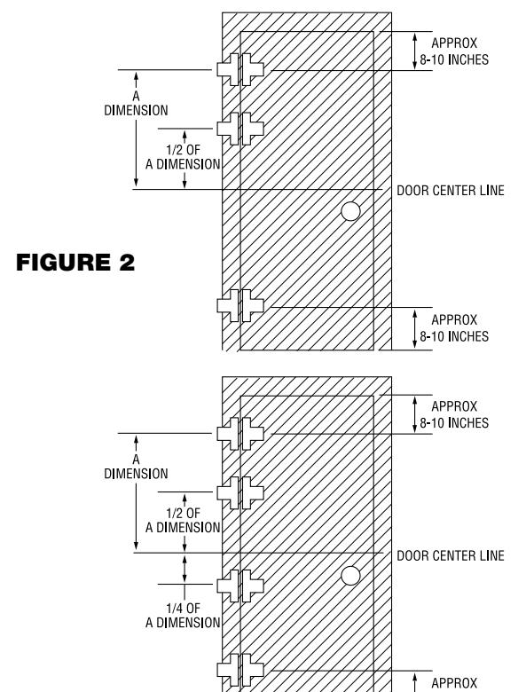
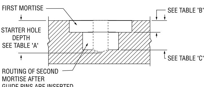
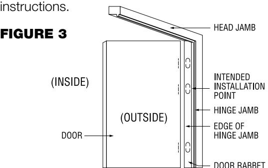
FIGURE 3 illustrates a typical door/jamb where SOSS Invisible Hinges will be mounted. Become familiar with the terminology as it will be used throughout these
Jamb Preparation (Refer to Figure 4)
- 1 Remove the guide pins from the router guide template.
- 2 Place the Router Guide Template on the hinge jamb so the locator pins rest flush against the pull side jamb face, and are on the inside of the intended door swing. The spacer tab should be flush against the head jamb, and positioned in line with the template (i.e. tab positioned as packaged).
- 3 Once the desired position is established, the nails can be tapped-in the door rabbet to secure the template in place.
FIGURE 4
4 REFER TO TABLE "A" to obtain the proper size drill or spade bit and starter hole depth.
TABLE A Starter Hole Depth
| SOSS Hinge Model | Drill Size | Starter Hole Depth* |
|---|---|---|
| #101 | 1/4" | 37/64" |
| #103 | 3/8" | 23/32" |
| #203 | 3/8" | 27/32" |
| #204 | 3/8" | 27/32" |
| #208 | 1/2" | 1-1/32" |
| #212 | 1/2" | 1-13/64" |
| #216/#416 | 1/2" | 1-9/16" |
| #218/#418 | 1/2" | 1-23/32" |
| #220 | 1/2" | 2-1/8" |
* The depth of the starter hole should be at least the values listed. Depths exceeding those tabulated will not adversely affect hinge operation.
5 Being careful not to nick or gouge the template, drill the starter hole for the router to the proper depth in the center of the hinge outline of the template.
Routing the Hinge Outline
6 The chart in TABLE "B" lists the maximum depths to which the hinge outlines should be routed. It is advisable to check the depth of the cut you are making prior to removing a significant amount of wood. If desired, the required depth may be obtained by making multiple router passes.
TABLE B Shallow Mortise
|
SOSS
Hinge Model |
Router
Bit Size |
Depth |
Recommended
Amana Tool Router Bit |
|---|---|---|---|
| #101 | 1/4"x 2-7/8" | 7/32" | 43828 |
| #103 | 3/8"x 3-1/4" | 7/32" | 46259S |
| #203 | 3/8"x 3-1/4" | 3/16" | 46259S |
| #204 | 3/8"x 3-1/4" | 1/4" | 46259S |
| #208 | 3/8"x 3-1/4" | 9/32" | 46259S |
| #212 | 3/8"x 3-1/4" | 3/8" | 46259S |
| #216/#416 | 1/2"x 4-1/2" | 15/32" | 51310 |
| #218/#418 | 1/2"x 4-1/2" | 13/32" | 51310 |
| #220 | 1/2"x 4-1/2" | 15/32" | 51310 |
Caution: Do not exceed the listed depths when routing the hinge outline, as binding of the hinges will occur.
7 Using whatever means of measurement best suited to you, determine the location of the next hinge to be mounted on the jamb. Mark or measure that distance so as not to damage the door.
NOTE: Remember the distances you have selected, as you will need to recall those measurements when mounting the templates on the door.
8 Remove the template from the jamb and move it to the new location you have chosen, repeating steps 2 through 7 for the number of hinges requiring installation.
Door Preparation (Refer to Figure 3)
- 1 Prior to mounting the template on the door, make certain that the door is properly oriented.
- 2 The clearance between the head jamb and the door is set with the spacer tab. It should be positioned one quarter turn so the template will hang from the top of the door.
- 3 Place the Router Guide Template on the door so the locator pins rest flush against the pull side face of the door, and are on the inside of the desired direction of the door swing.
- 4 Once the desired position is established, the nails can be tapped in to secure the template in place.
- 5 Again, being careful not to nick or gouge the template, drill the starter hole for the router to the depth listed in TABLE "A" in the center of the hinge outline of the template.
- 6 The chart in TABLE "B" lists the maximum depths for which the hinge outlines should be routed. It is advisable to check the depth of the cut you are making, prior to removing a significant amount of wood. If desired, the required depth may be cut in multiple passes.
- 7 Recalling the measurements you made to determine the hinge spacing on the jamb, use those identical measurements to position the template for the next hinge mortise on the door.
- 8 Remove the template from the top of the door and move it to the new location repeating steps 3 through 7 for the number of hinges requiring installation.
At this point, the routing of the outline portions of the hinge mortises is complete. The next step is to rout the deep mortises.
Place the guide pins into their proper holes on the template. The guide pins are threaded and must not be hammered or otherwise forced into position. Care must also be taken that the threaded guide pins are not overtightened, as this may distort the templates.
Completion of the Jamb Mortises (Refer to Figure 1)
- 1 Starting at the top hinge mortise, position the template so the nails fit into the holes left in the jamb from the previous rout. The locator pins should be toward the inside of the door swing as before.
- 2 Once the proper position is reestablished, the nails can be tapped in to secure the template in place.
- 3 To complete the routing of the hinge mortise, it will be necessary to remove wood to the depth listed in TABLE "C". It is recommended that multiple passes be made, as opposed to removing all of the wood at once.
TABLE C Deep Mortise Depth
| SOSS Hinge Model | Deep Mortise Depth |
|---|---|
| #101 | 33/64" |
| #103 | 21/32" |
| #203 | 25/32" |
| #204 | 25/32" |
| #208 | 31/32" |
| #212 | 1-9/64" |
| #216/#416 | 1-1/2" |
| #218/#418 | 1-21/32" |
| #220 | 2-1/16" |
CAUTION: Rout only the area between the guide pins. Do not remove any more material from the circular outline or any outside the guide pins.
- 4 After the deep mortise has been routed, remove the template.
-
5 Place a SOSS Invisible Hinge into the mortise you have completed and inspect the following:
- A Does the hinge fit "snugly" into the mortise?
- B Does any portion of the hinge extend beyond the rabbet of the jamb?
The body of the hinge should fit snugly into the mortise. If the hinge body extends above the jamb after the hinge has been pushed into the mortise as far as possible, verify that the mortises have been routed to the proper depths. Correct as required.
6 Position the template at the next location on the jamb. Repeat steps 1 through 5 for the number of hinges requiring installation.
Completion of the Door Mortises (Refer to Figure 1)
- 1 Position the template so the nails fit into the holes left in the door from the previous rout. The locator pins should be toward the inside of the door swing as before.
- 2 Once the proper position is reestablished, the nails can be tapped in to secure the template in place.
- 3 To complete the routing of the hinge mortise, it will be necessary to remove wood from the door to the depths listed in TABLE "C". Again, it is recommended that the wood be removed by making multiple router passes.
- 4 After the deep mortise has been routed, remove the template from the door and position it at the next hinge location on the door.
- 5 Repeat steps 1 through 4 for each hinge requiring installation.
Mounting the Door to the Jamb
Having completed the routing of the hinge mortises, notice that the hinge mortise is not centered within the thickness of the door. The "thin" section corresponds to the inside surface of the door.
- 1 Place the SOSS Invisible Hinges into the mortises so the hinge bodies straddle the thin section of the door. Using the wood screws supplied with the hinges, secure the hinges to the door.
- 2 The door can then be moved into a position where the remaining hinge bodies can be placed into their respective mortises in the jamb.
- 3 Secure the jamb side of the hinges with the remaining wood screws.
- 4 Exercise the door to see that it opens and closes freely throughout the required amount of opening.
- 1 Place the routed side of the wood router guide (refer to illustration below) into a slotted aluminum channel rail. Slide the guide to the end of the channel so the wood is flush with the aluminum.
- 2 Place small tooth washer on wood screw. Slip screw through the slot in the channel and screw it into the wood hole closest to the flush end. Tighten.
- 3 Turn the spacer tab on the flush end of the guide one quarter turn.
- 4 Put screws and washers into any two remaining router guide holes and tighten.
- 5 Slide a second router guide into the other end of the above channel/guide assembly. Slide the guide about two inches into the channel.
- 6 Place a small washer on a wood screw. Slip the screw through the slot in the channel. Turn it into the hole in the wood. Do not tighten.
- 7 Place another channel on the guide and insert two washers and screws as before. Do not tighten them.
- 8 Turn a machine screw in each TAPPED hole in the angle rail so that screw head is inside the rail's corner.
- 9 Place the angle rail into the end of the channel so one screw extends into the slot in the channel and the angle extends 6" beyond the channel.
- 10 Place a large tooth washer over the screw, turn on a wing nut. Do not tighten.
- 11 Place the third channel over the angle and secure with machine screw washer and wing nut but do not tighten.
- 12 Put the remaining router guide into the channel and secure with three screws and washers. Do not tighten.
- 13 Put nails into the holes in each end of the guide
- 14 Hang the assembly from the top of the door, using the spacer tab in step 3. Rotate clip a half turn if required. The two locator pins in each guide should be against the pull side face of the door. Lay the door on its edge as shown in the illustration below.
- 15 Slide each router guide to the desired location and tighten all loose screws. See attached "Instructions for Mounting Soss Invisible Hinges Using The Hinge Guide Template" to determine each guide's location.
- 16 Partially drive the nails into the door, only far enough to secure the location of each router guide.
- 17 To rout the mortise, follow the procedure on "Instructions for Mounting SOSS Invisible Hinges Using the Router Guide Template".
- 18 After routing the door, pull the nails out of the door. It is not necessary to pull the nails out of the pre-drilled holes in the guide.
- Place the entire assembly against the hinge jamb with the spacer tab snug against the head jamb.

Phone: (419) 737-2324 (800) 922-6957, FAX: (419) 737-2130
Email: hinges@soss.com Internet: www.soss.com