SCHLAGE L9000- SCHLBMKIT-ML Installation Instruction
Open the original PDF document
View PDF


SCHLBMKIT-ML
I N S E R T I n s t r u c t i o n s
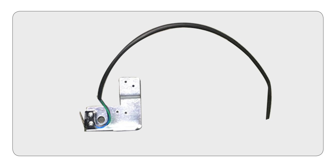
Field Installable Latchbolt Monitor switch for Schlage L9000 mortise lock. The kit's easy "drop-in" installation adds a switch that monitors the position of the latchbolt. The switch is SPDT (single pull, double throw).
SPECIFICATIONS AND CONENT
ML80, 82, 480, & 485 1 - Bracket with LBM Switch SERIES: INCLUDED:
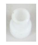
.25A @ 24VAC/DC 1 - LBM Sticker 1 - Strain Relief RATING:
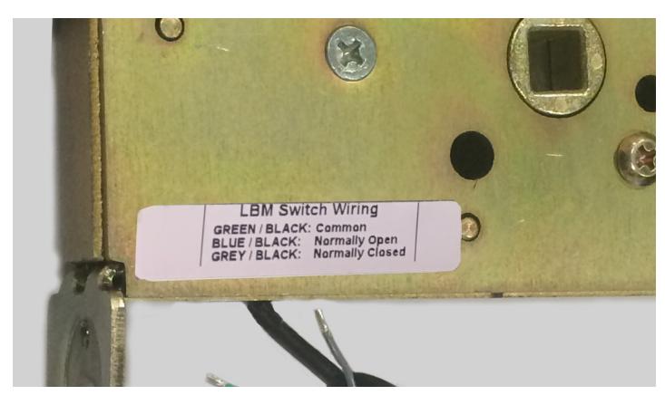
Green/Black - Common (C) 1 - Fire door fuse CONFIGURATION:
Blue/Black - Normally Open (NO) Gray/Black - Normally Closed (NC)

I n s ta l l at i o n I n s t r u c t i o n s

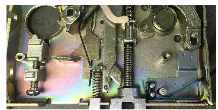
Remove cover plate (4 screws). A.
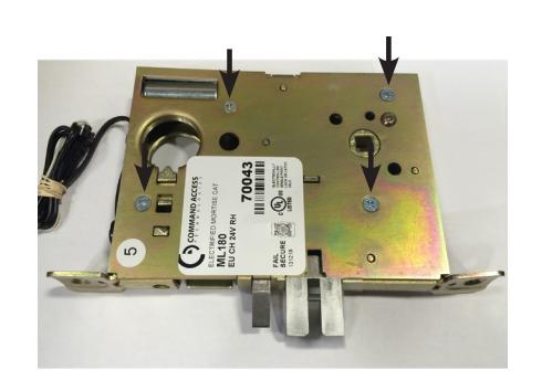
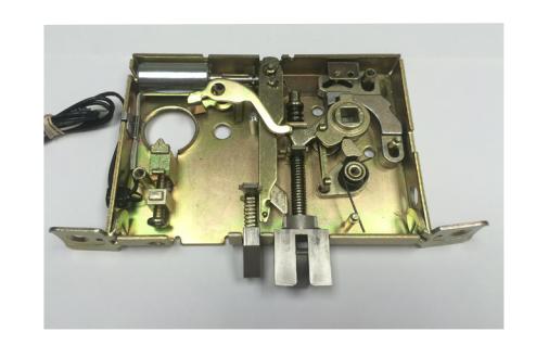
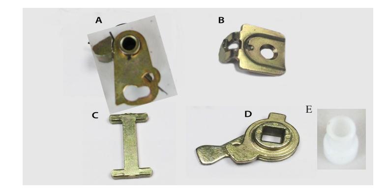
Remove following items: B.
A. Hub Center Spring Assembly
- B. Mounting Tab
- C. Retractor Link
- D. Retractor Hub
- E. Fire door fuse
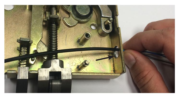
Fish wires through bottom hole. C.
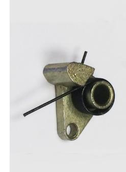
Place bracket over post & replace Mounting Tab(B.) to secure bracket. D.
I n s ta l l at i o n I n s t r u c t i o n s

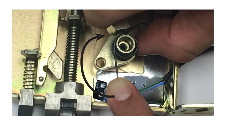
Replace Hub Center Spring Assembly(A.). Line up & place over posts so it lightly rests on switch. E.
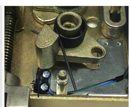
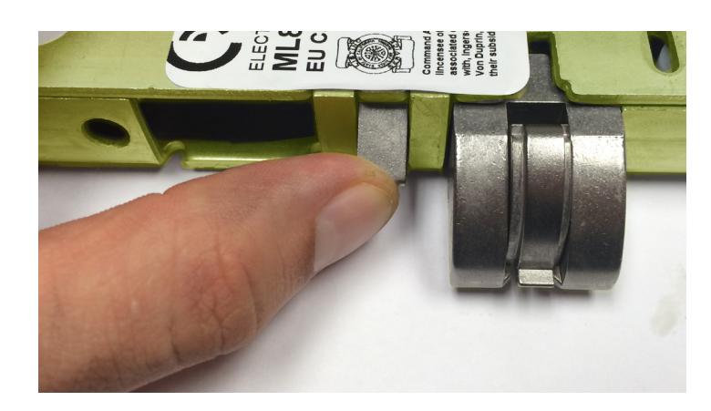
One finger positioned on the post & the other on the tab. Rotate by pushing clockwise on the Hub Center Spring Assembly. F.
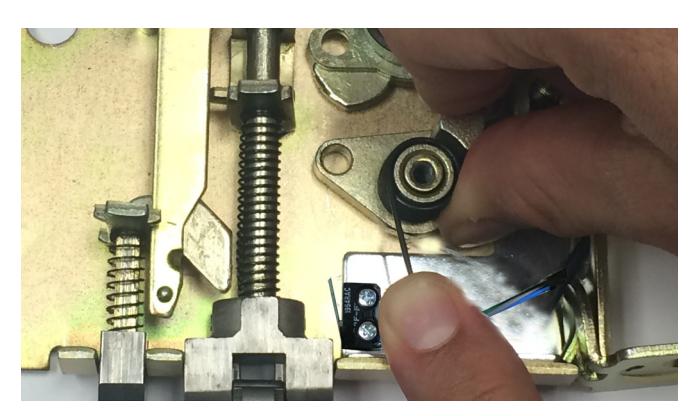
Once Hub Center Spring Assembly has rotated to desired position, past the switch, push down until it hits bottom of lock body. G.
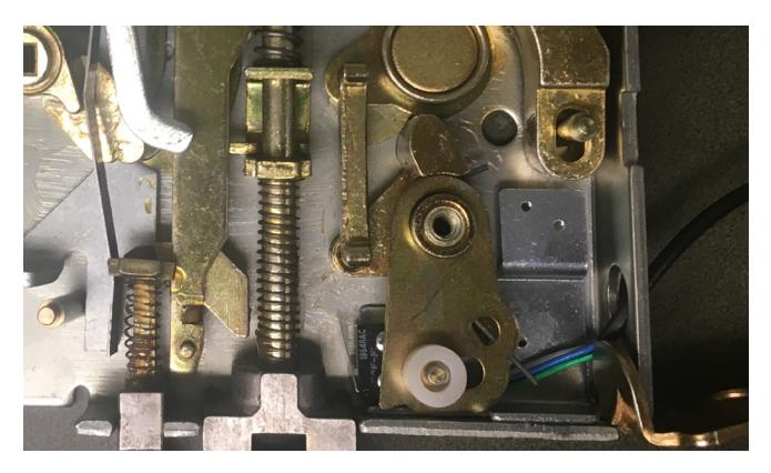
Replace Retractor Link(C.) & Retractor Hub(D.). Add Fire door fuse H.
I n s ta l l at i o n I n s t r u c t i o n s

Replace cover. If needed pull on anti-pick and push on latchbolt to help case slip together. Test that latchbolt & anti-pick function. I.
Re-install cover and tighten 4 screws and place wiring code sticker on case. J.
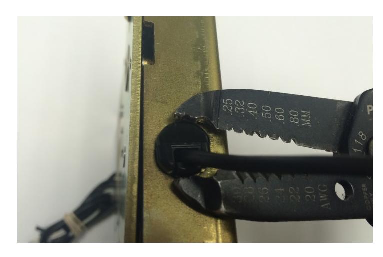
Pull slack out of the switch wires and install strain relief. K.
TESTING FOR CONTINUITY
Continuity should change state when either lever is turned:
Normally Open (NO) : Green and Blue Normally Closed (NC) : Green and Gray