SARGENT Mortise Exit Device 9900 and 12-9900 Series Intallation Instructions
Open the original PDF document
View PDFInstallation Instructions

9900 & 12-9900
Mortise Lock Exit Device
See Figure 1 for identification of parts.
Review the dimensions on the template to obtain the correct height from finished floor.
- 1. Locate and place template as follows:
- a. Stick center case and lock front template on door as illustrated in Figure 2.
- b. Using the cross bar hole centers for measuring, locate the vertical center line of bracket.
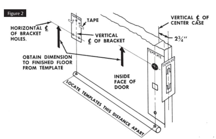
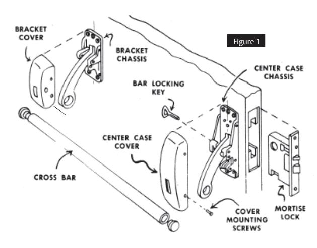
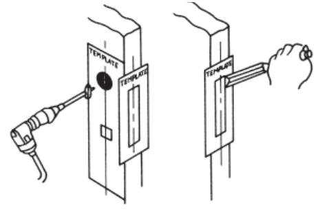
Figure 3
- 2. Drill holes and mortise for lock as directed by the templates. See Figure 3.
- 3. If screwless rose outside trim is used, see separate instruction sheet and install rose at this time. See Figure 4.
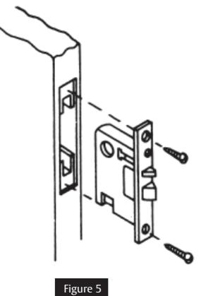
- 4. Fasten mortise lock in place. See Figure 5.

- 5. IMPORTANT: Mount the center case chassis as follows:
- a. Remove cover from center case chassis. Lock down arm. (For exit devices less the cross bar lock down feature, hold arm in depressed position.) See Figure 6.
- b. Position center case chassis against the door so that the center case lever is under the rear lever of themortise lock.
- c. Lift center case chassis upward until the latch bolt is completely retracted.
- d. With chassis in this position, mark location of the screw holes.
- e. Drill holes for screws and mount center case chassis to the door.
NOTE: If thru bolted trim is used, drill four 7/32" diameter holes through the door and counterbore outside of the door for lugs.
- 6. Attach outside trim when used.
- a. Install cylinder and tighten cylinder set screw in lock front.
- b. Attach center case cover to chassis.
- 7. Mount bracket chassis on door and attach bracket cover to chassis.
- 8. Assemble and secure cross bar to arms.
- 9. Mortise strike in position.
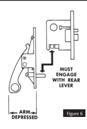
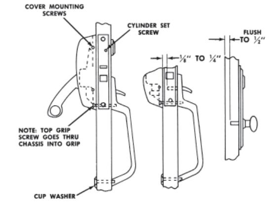
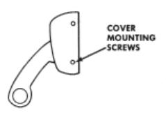
Figure 7