SARGENT Bored Lock 11 Line All Functions Installation Instructions
Open the original PDF document
View PDFINSTALLATION INSTRUCTIONS FOR 11 Line
SARGENT
ΔS
FOR ASSISTANCE, CONTACT SARGENT AT 800-727-5477 or <a href="https://resources2.locksandsafes.com/static/html/SARGENT-Bored-Lock-11-Line-All-Functions-Installation-Instructions-82d6ece8/www.sargentlock.com">www.sargentlock.com</a> Patent pending and/or patent www.assaabloydss.com/patents
ASSA ABLOY
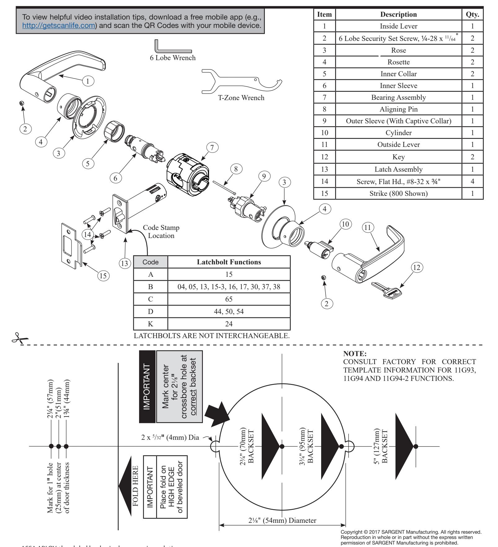
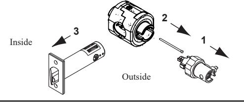
4 Lock Disassembly
- 2. Remove aligning pin from bearing assembly.
- 3. Separate latch from bearing assembly.

Scan to see a video of this installation step.
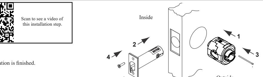
5 Latchset Installation
Hold door open with door stop:
- 1. Insert bearing assembly.
- 2. Insert latch assembly.
- 3. Insert aligning pin from secure side (outside) of door.
- 4. Install latch plate screws. Do not tighten completely until lock installation is finished.
6 Function Specific Instructions - Sleeve Assembly
IMPORTANT: Sleeves with colored driver tips require that the slotted cam be rotated allowing the spring loaded locking piece to move freely in and out of the outside sleeve.
Driver Tips with red markings must match up before assembling lock.
Note: Some driver tips have two color markings for function identification
11G54 – green 11U65 – blue 11G24 – yellow 11G05 – only red
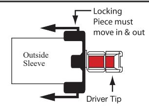
Note: Outside sleeve has collar attached. Outside Sleeve "Spring loaded"
See Specific Instructions Per Function. Identify Function On Box (Example: 11G05)
For functions not shown, proceed to step 7
| Outside Sleeve | Function Number | Function Description | Inside Sleeve | |
|---|---|---|---|---|
| 05 Entrand | Storeroom/Closet | |||
| 05 | Entrance/Office | Follow Step 7 | ||
| 16 | Classroom Security/Apartment | |||
| Align driver tips matching the painted sections | 17 | Utility/Asylum | Scan to see a video of this installation step. | |
| 24 | Entry | |||
| 05 Entrance/Office 16 Classroom Security/Apartment 17 Utility/Asylum | Follow Step 7 | |||
| 65 | Privacy/Bathroom | |||
| 38 | Classroom Security | Follow Step 7 | ||
| 54 | Dormitory | |||
| See A7608B | 50 | Hotel/Motel | See A7608B | |
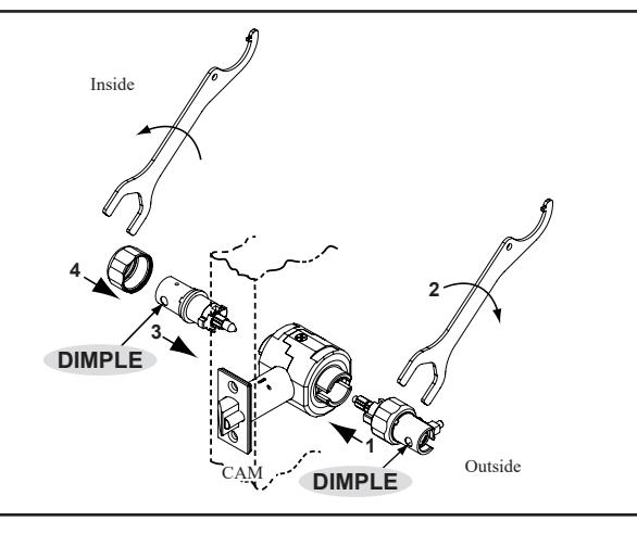
Sleeve Installation
- 1. With driver tips aligned, insert outside sleeve first. Dimple must face door edge.
- 2. Thread outside collar by hand. Tighten to bearing assembly with wrench.
- 3. Insert inside sleeve. Dimple must face door edge.
- 4. Thread inside collar by hand. Tighten to bearing assembly with wrench.
Caution: If excessive wrench torque is required, stop and check alignment of driver tips.

Scan to see a video of this installation step.
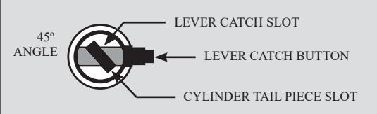
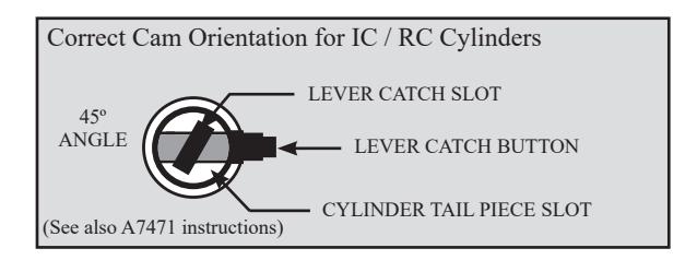
Cam Orientation
- 1. Lock lever by button if applicable.
- 2. Turn slotted cam until lever catch button can be depressed.
Scan to see a video of this installation step.
NOTE: Dark colored cams on the inside designate for use with standard cylinders. Silver colored cams on the inside designate for use with IC / RC cylinders.

9 Rose Installation
- 1. Slide rose over sleeves aligning tabs on rose with slots on bearing assembly.
- 2. Hand tighten rosettes to door surface.
Caution: If excessive wrench torque is required, stop and check for cross-threading.
Note: Rosettes must be tightened simultaneously to ensure proper centering of lock on door.

Scan to see a video of this installation step.
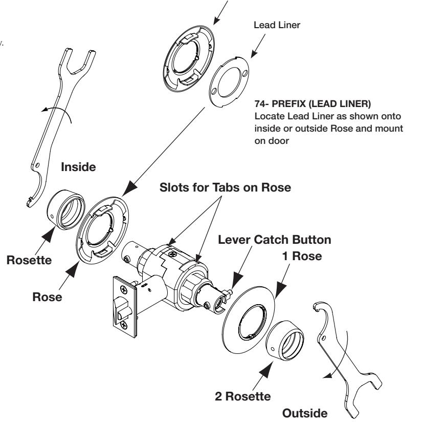
Rose

Function Specific Directions - Lever Installation
For functions not shown, proceed to step 10.
| Inside Sleeve | Function | Function Description | Outside Sleeve | |
|---|---|---|---|---|
| Lock lever by button | 05 | Entrance/Office | ||
| 24 | Entry | |||
| 44 | Service Station | Rotate cam until lever catch button Scan to see a | ||
| 65 | Privacy / Bathroom | Rotate cam until lever catch button video of this can be depressed, holding cam in video of this installation step. | ||
| 04 | Storeroom / Closet | rotated position. | ||
| Rotate cam until lever catch button can be depressed, holding cam in rotated position | 17 | Utility / Asylum | ||
| Rotate cam counterclockwise until it stops | 16 | Classroom Security / Apartment | Rotate cam until lever catch button can be depressed. | |
| 30 | Communicating | Rotate cam counterclockwise until it stops. Then rotate back 45° until lever catch button can be depressed. | ||
| 38 | Classroom Security | Rotate cam counterclockwise until it stops. Then rotate back 45° until lever catch button can be depressed. | ||
| Lock lever by button | 54 | Dormitory | Rotate cam counterclockwise until it stops. Then rotate back 45° until lever catch button can be depressed. | |
| See A7608 | 50 | Hotel / Motel | See A7608 | |
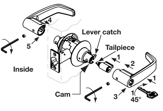
10 Lever Installation
- For conventional cylinder, place cylinder into lever. Insert key and turn 45° CLOCKWISE to align cylinder tailpiece with deep slot in cam (see slotted cam illustration in step 8). For removable or interchangeable core, see separate instruction sheet (A7471).
- 2. Install outside lever. Push on until lever catch engages.
Note: If outside lever will not secure in place, rotate key clockwise until lever catch is released.
- 3. Secure with 6 lobe security set screws until flush with lever surface.
- 4. Install inside lever. On 17 and 30 functions, push on until lever catch engages.
- 5. Secure with 6 lobe security set screw until flush with lever surface.
- 6. Complete tightening of two (2) latchbolt screws.
- 7. Check operation of levers and latchbolt before closing door.

Scan to see a video of this installation step
Outside
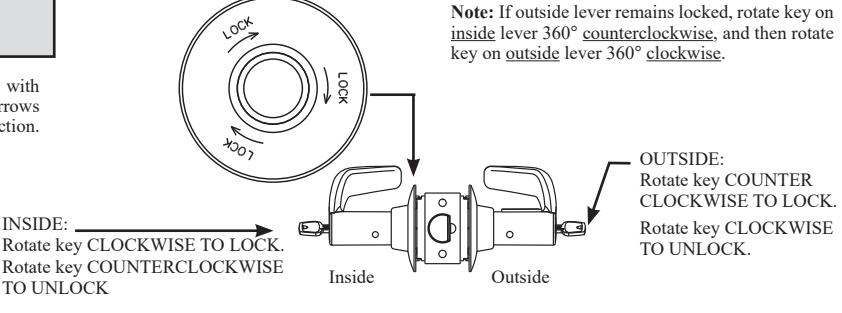
11 | 11G38 Classroom Security Function
Function Description: Inside lever is always unlocked. Inside key locks /unlocks outside lever. When inside key locks outside lever, outside key retracts the latchbolt but cannot unlock the outside lever.
Inside rose is marked with "Lock" and direction arrows to indicate locking direction.
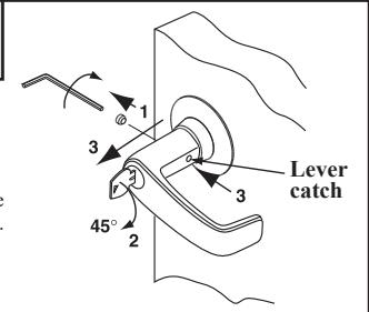
12 | Cylinder Removal (Conventional)
- 1. Remove 6 lobe security set screw.
- 2. Insert key and rotate 45° clockwise to release lever catch.
- 3. Depress lever catch and remove lever.
Note: Removable and interchangeable core cylinders do not require removing the lever to install. See separate instruction sheet (A7471).
13 | 11U65 Outside Lever Removal
- Remove 6 lobe security set screw.
- 2. Lock outside lever by pushing in button on inside lever.
- 3. Rotate slot on outside lever with flat blade screwdriver to release lever catch and hold in place.
- 4. Depress lever catch and remove lever.