S6200, TEMP-S6200-EKE03-GKE03 CAD Template
Open the original PDF document
View PDF

801 Avenida Acaso, Camarillo, Ca. 93012 • (805) 494-0622 • Fax: (805) 494-8861 www.sdcsecurity.com •E-mail: service@sdcsecurity.com
Security Door Controls
TEMPLATE-S6200, TEMP-S6200-EKE03-GKE03 SURFACE MOUNT VERTICAL ROD
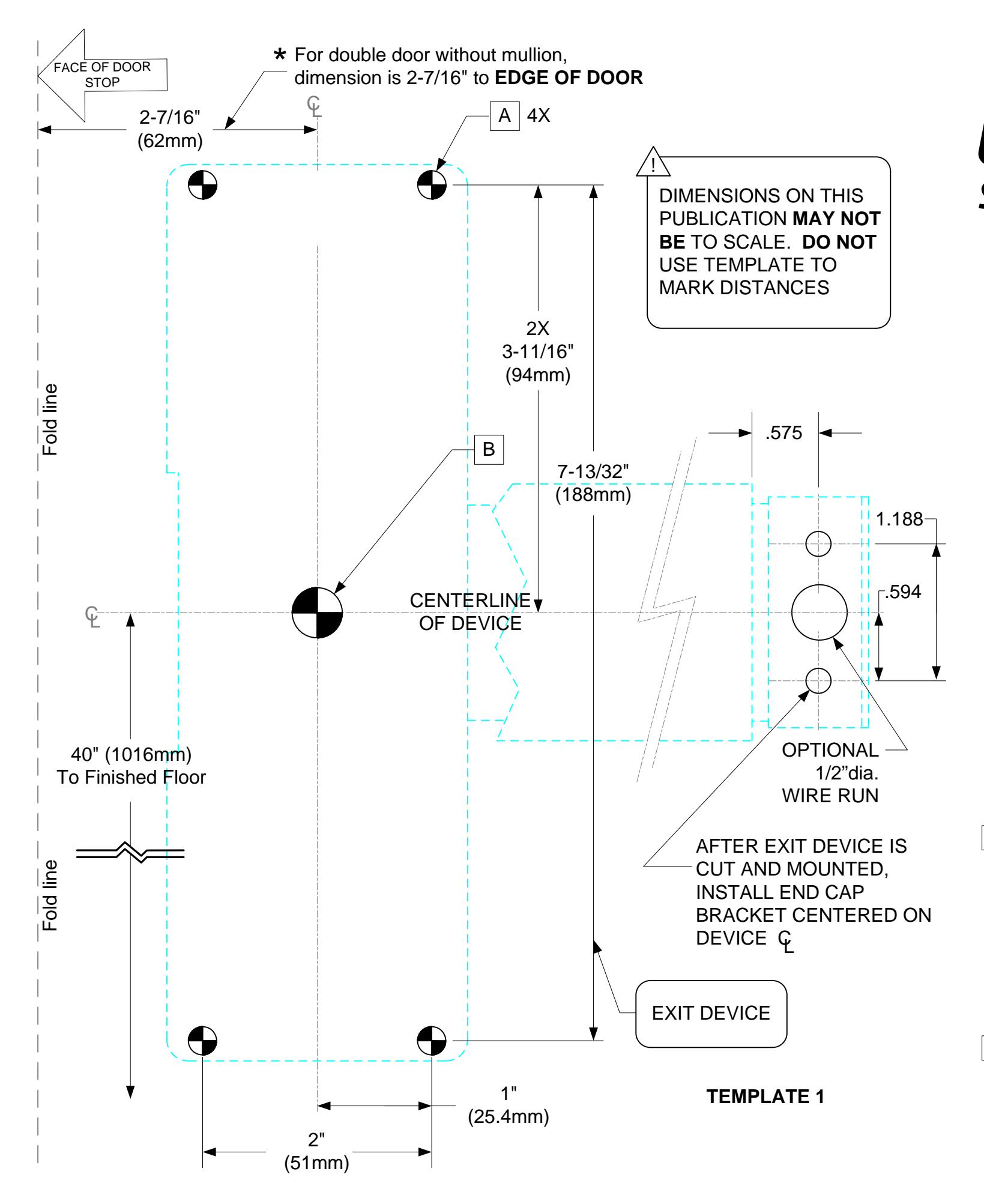
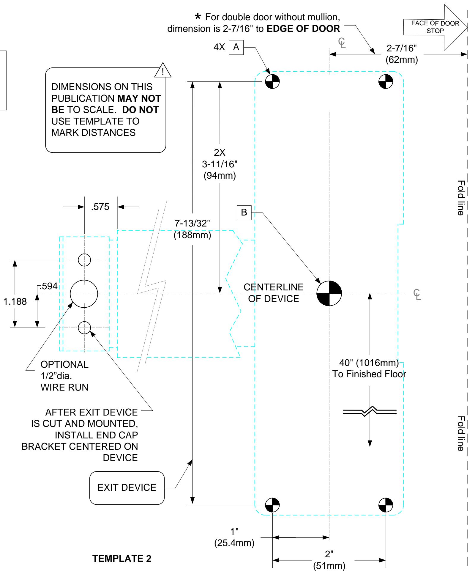
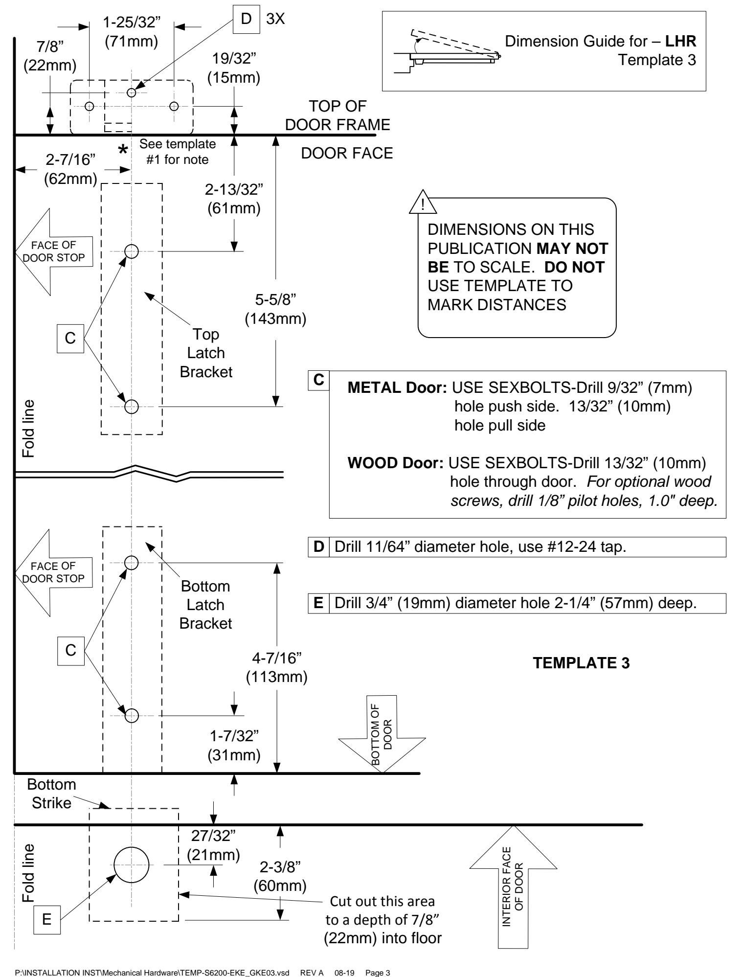
Dimension Guide for - LHR (Left Hand Reverse door) Template 1
- 1. Draw a centerline horizontally across the door, 40" (1016mm) from bottom of door.
- 2. Draw a vertical centerline 2-7/16" (62mm) from edge of door.
- 3. Select the appropriate side of both templates. (1 & 2). Your door handing will determine the appropriate side, either (LHR) or (RHR).
- 4. Using dimensions indicated on templates 1 & 2, locate and mark the center of the required holes.
- 5. Drill holes as indicated by their designated letter.
- 6. If using an exterior trim, refer to the template with trim to further prepare door.
METAL - Panic Rated: Drill/Tap for 1/4-20 machine screws (sexbolts recommended).
METAL - Fire Rated: Sexbolts required.
SEXBOLTS: Drill 3/8" (9.5mm) clearance holes on Push and Pull Sides.
WOOD: Pre-Drill 1/8" (3mm) hole.
ACTUATING SHAFT HOLE: Drill 1/2" thru hole.
Any suggestions or comments to this instruction or product are welcome. Please contact us through our website or email engineer@sdcsecurity.com
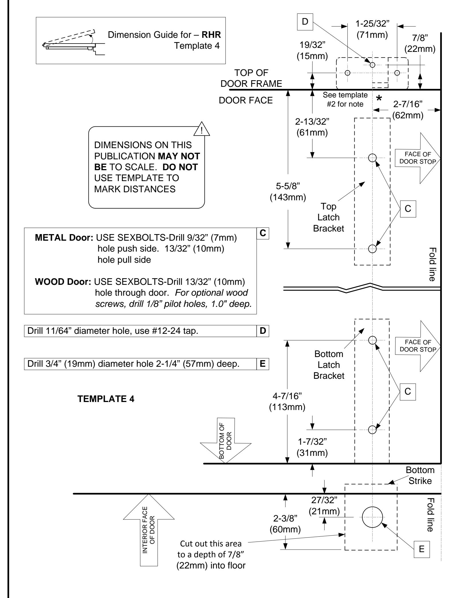
Dimension Guide for – RHR (Right Hand Reverse door) Template 2
В
- 1. Draw a centerline horizontally across the door, 40" (1016mm) from bottom of door.
- 2. Draw a vertical centerline 2-7/16" (62mm) from edge of door.
- 3. Select the appropriate side of both templates. (1 & 2). Your door handing will determine the appropriate side, either (LHR) or (RHR).
- 4. Using dimensions indicated on templates 1 & 2, locate and mark the center of the required holes.
- 5. Drill holes as indicated by their designated letter.
- 6. If using an exterior trim, refer to the template with trim to further prepare door.
METAL - Panic Rated: Drill/Tap for 1/4-20 machine screws (sexbolts recommended).
METAL – Fire Rated: Sexbolts required.
SEXBOLTS: Drill 3/8" (9.5mm) clearance holes on Push and Pull Sides.
WOOD: Pre-Drill 1/8" (3mm) hole.
ACTUATING SHAFT HOLE: Drill 1/2" thru hole.
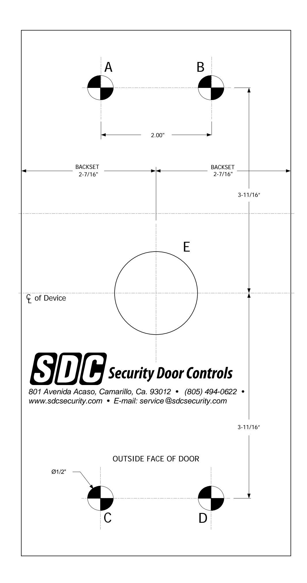
TEMPLATEELECTRIC TRIMEKE03/GKE03 SERIES
Simple Instructions:
- 1. Using a 1/2" drill at locations A, B, C & D, drill four holes through to accept the four escutcheon standoffs.
- 2. Drill or saw a 1.50" dia hole at location E.
- 3. Fasten the supplied mounting screws into the hex standoffs on the trim, from the inside of the door. The four screws must go through the chassis of the exit device.
- 4. Install cylinder. See installation instructions of Rim Exit Device.
NOTE:
- 1. For single doors and double doors with mullion, use the backset dimension of 2-7/16" to FACE OF STOP.
- 2. Dimensional drawing, not to scale.
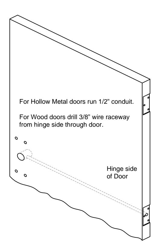
ELECTRIC TRIM WIRES MUST BE WIRED THROUGH THE DOOR RACEWAY AND NOT THROUGHTHE EXIT DEVICE