S4200 SVR Installation Instructions
Open the original PDF document
View PDF

[t] 800.413.8783 ■ 805.494.0622 ■ E-mail: service@sdcsecurity.com ■ 801 Avenida Acaso, Camarillo, CA 93012 ■ PO Box 3670, Camarillo, CA 93011
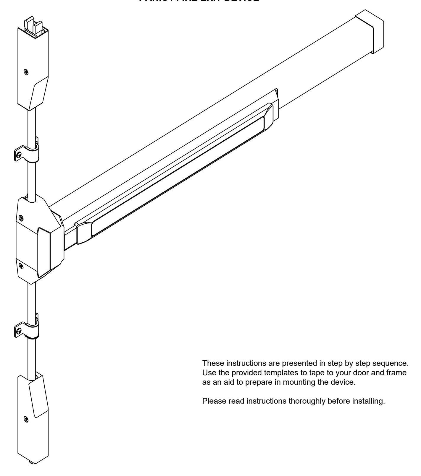
INSTALLATION INSTRUCTIONS
S4200 SURFACE VERTICAL ROD PANIC / FIRE EXIT DEVICE

[t] 800.413.8783 ■ 805.494.0622 ■ E-mail: service@sdcsecurity.com ■ 801 Avenida Acaso, Camarillo, CA 93012 ■ PO Box 3670, Camarillo, CA 93011
STEP 1: PREPARE DOOR
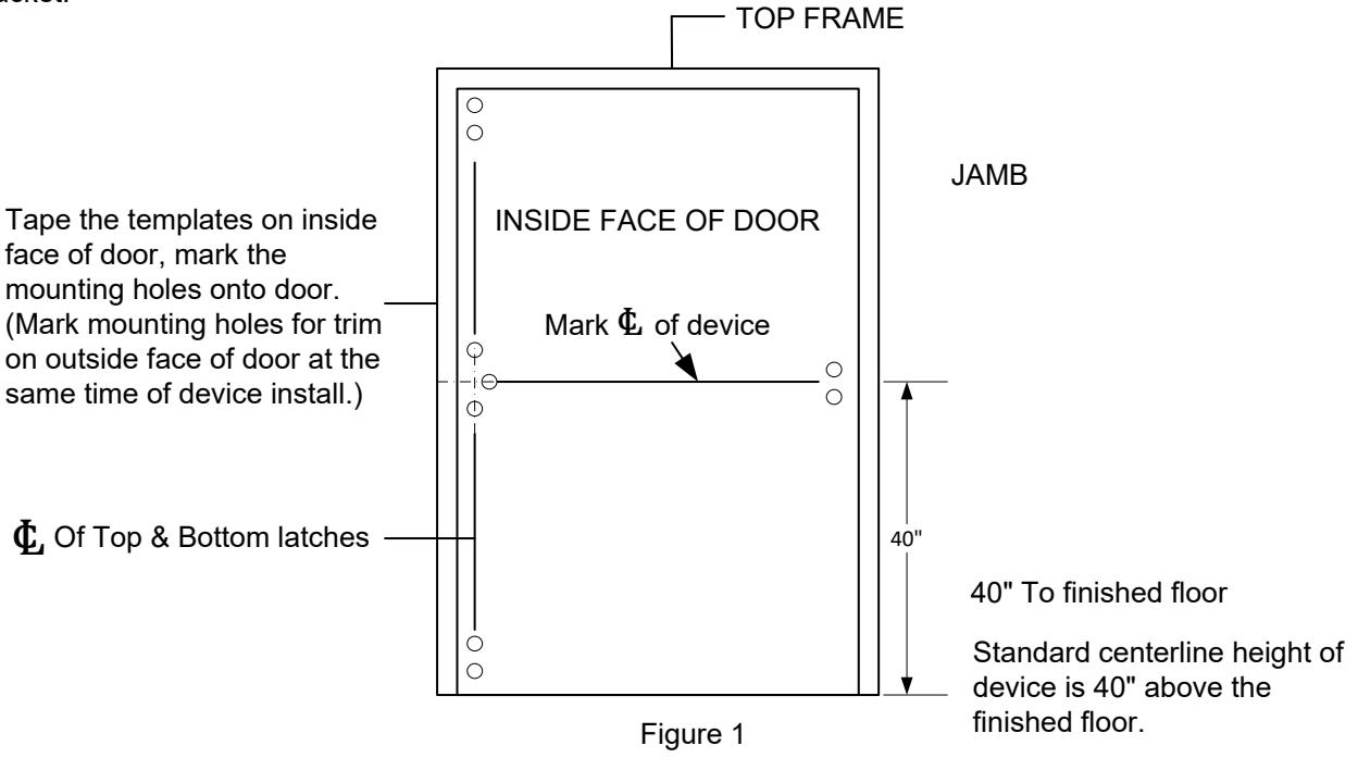
- 1. Mark position of holes on the door with templates. (See Figure 1.)
- 2. Spot and drill all holes as marked on door for device chassis, top & bottom latch mounting brackets and end cap bracket.
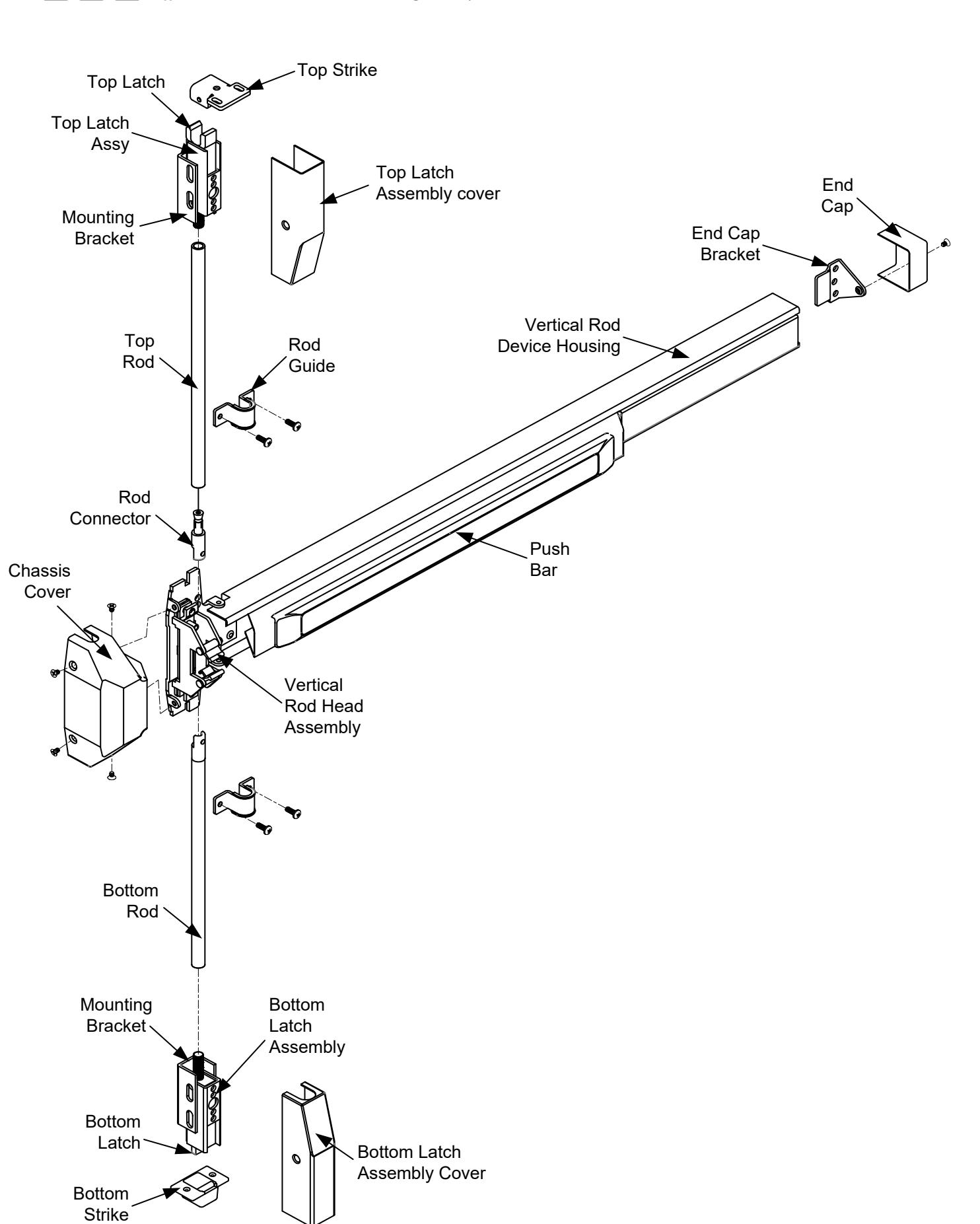
STEP 2: INSTALL BRACKETS, DEVICE & TRIM
- 1. Remove chassis cover from chassis assembly and end cap from end cap bracket.
- 2. The length of devices are precut for 36" wide door use, no additional cutting is necessary.
Note:
This device can't be cut shorter than the standard width or will damage the ELR.
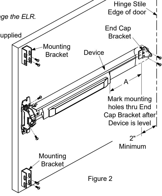
3. Mount device horizontally to the drilled position securing it with the supplied
mounting screws, or with device trim.
(See Trim Installation Instructions.)
-
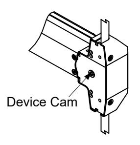
4. Make sure that the trim actuating shaft can insert into device cam.
- (See the figure of Device Cam below.)
- 5. Install end cap bracket on device then screw to door.
(Make sure the device is level.)
6. Install two mounting brackets on top and bottom of the door.


Insert Trim actuating shaft Into Device Cam
Bottom Latch

STEP 3: INSTALL BOTTOM ROD AND BOTTOM STRIKE 1. Mount bottom latch assembly into mounting bracket. (See Figure 3.) Bottom Latch Assembly Mounting Bracket Figure 3
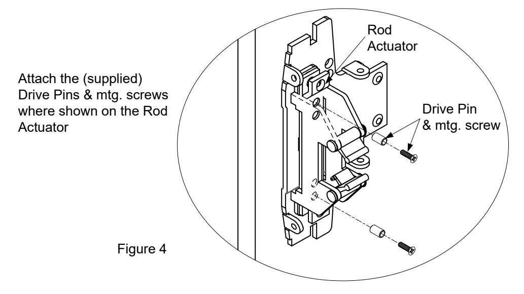
2. Fasten the Drive Pin into both sides of Rod Actuator as shown in Figure 4.
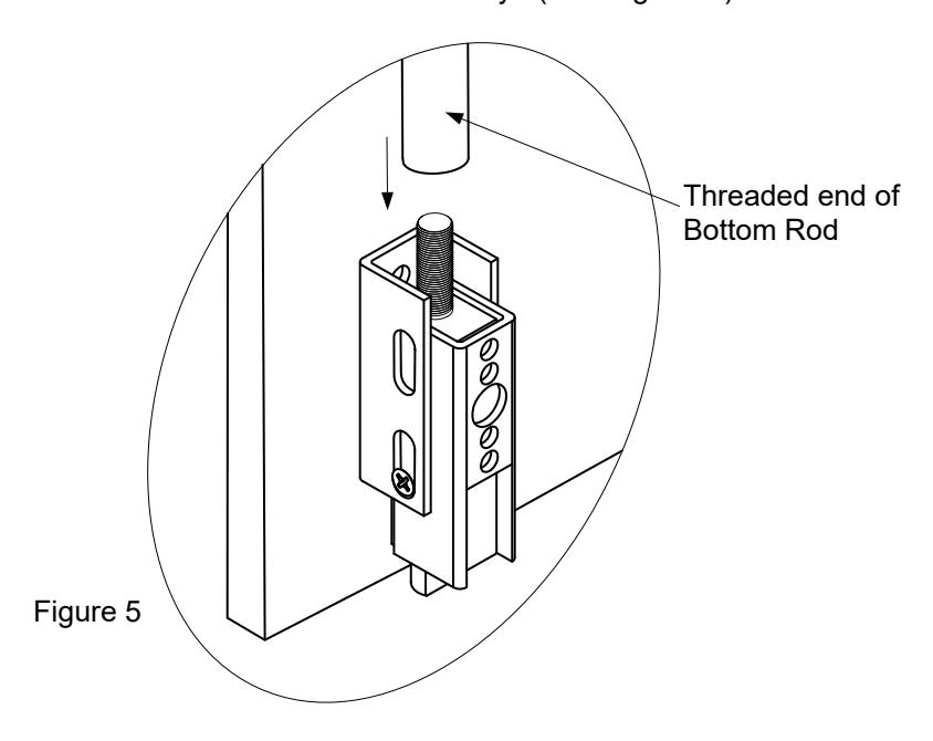
3. Screw the threaded end of bottom rod in to bottom latch assembly. (See Figure 5.)

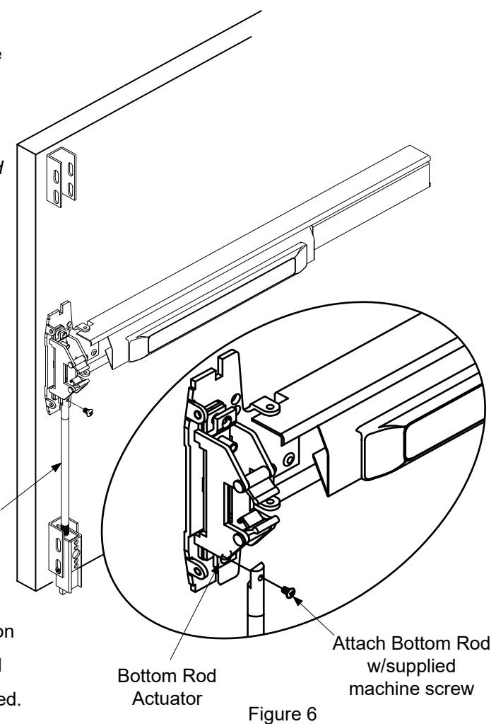
in the down position (Figure 6). 4. Attach Bottom Rod to Bottom Rod Actuator which should be
Note: If the hole on the bottom rod connector does not match alignment with the mounting hole of the Rod Actuator, then adjust the height of the bottom rod as shown in Figure 5.
5. Install bottom strike into finished floor and be sure to align center line of bottom latch with the center line of the bottom
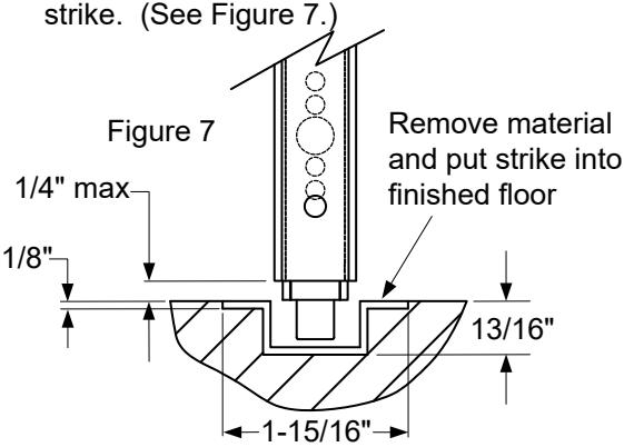
Bottom Rod
- 6. Depress and release push bar to check for correct installation
- 6 1. Make sure the bottom latch can be held retracted and flush with the edge of door when push bar is depressed.
- 6 2. Check the bottom latch bolt to make sure that it has a minimum throw of 3/8" when push bar is released.
STEP 4: INSTALL TOP ROD AND TOP STRIKE
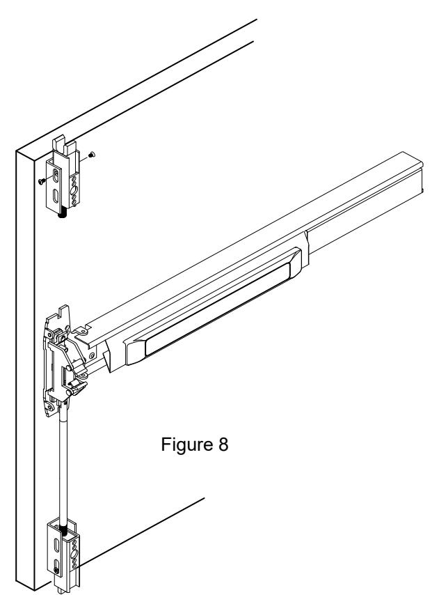
- 1. Mount top latch assembly into mounting bracket. (See Figure 8.)
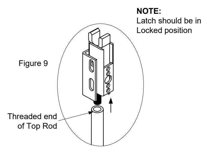
- 2. Fasten the threaded end of the top rod into the top latch assembly. (See Figure 9.)

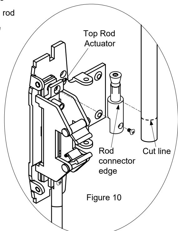
3. Measure and cut the length of the top rod. The length of the top rod is measured from the edge of the connecting rod, to top of the threaded rod on the latch assembly. Mark a cutting line on the rod and remove the excess portion (Figure 10).
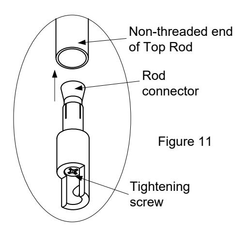
4. Insert the rod connector into the non-threaded end of the top rod and tighten the screw. (See Figure 11.)
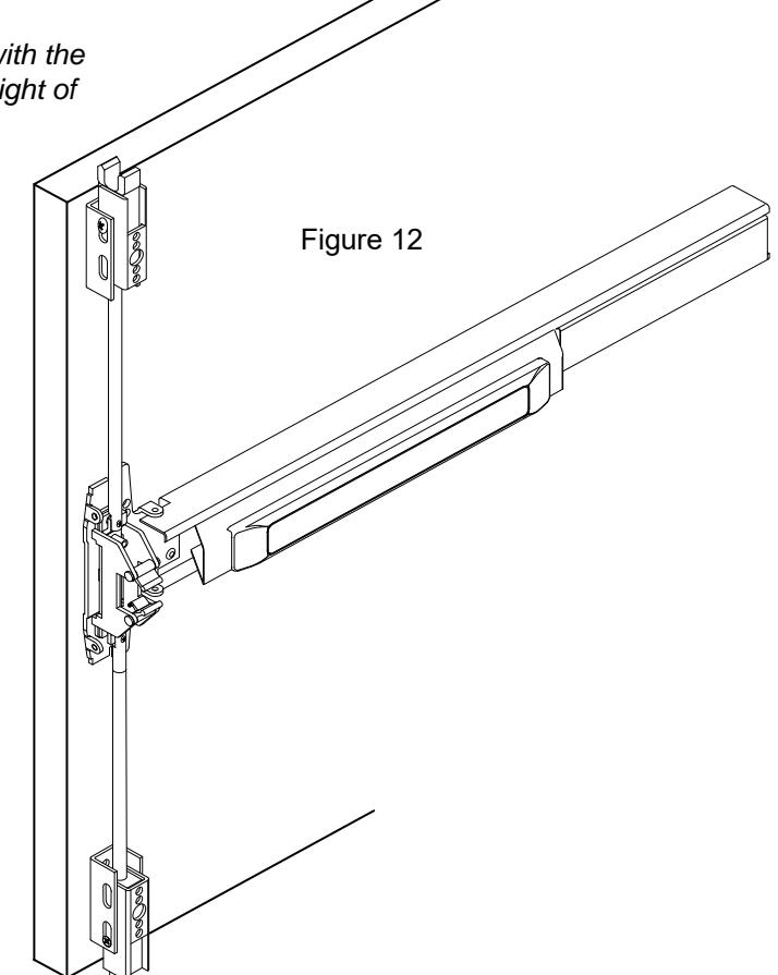
5. Attach the top rod (with the rod connector attached) to the top latch assembly (Figure 12).
Note: If the hole on the top connecting rod does not align with the mounting hole of the rod actuator, then adjust the height of the top rod as shown in Figure 9 or re-cut to length.

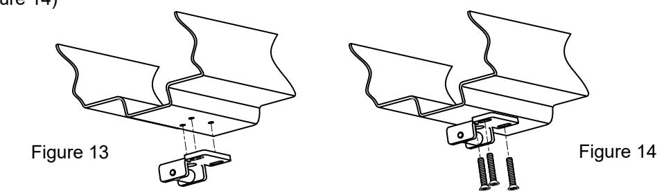
7. Mark mounting holes for top strike on jamb with Strike Template (See Figure 13.), then fasten using supplied screws. (See Figure 14)
STEP 5: WIRING THE ELR (Electric Latch Retraction)
1. Using a 24VDC regulated power supply, wire the (+) RED wire lead from the device to the (+) positive side of power source. Wire the (-) BLACK wire lead from the device to the (-) negative side of the power source. (See Figure 15)
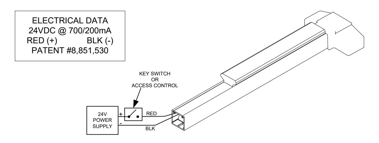
Figure 15
STEP 6: TEST OPERATION
- 1. Depress the push bar and verify that the top and bottom latch are retracted while the push bar is held. Verify that the top and bottom latch is capable of clearing the strikes while the door is pushed open.
- 2. Release the push bar and verify that the top and bottom latch are fully extended.
- 3. Check the device operation by depressing and releasing the push bar several times to assure proper alignment.
- 4. Repeat device operation by opening and closing the door several times. Test with trim if a trim is used to assure that installation is correct.
- 5. Repeat adjustment procedure if either top or bottom latch are not retracted when push bar is held and or if the latch does not clear the floor or strike.
- 6. Disconnect the vertical rods from the device and energize the ELR so that the push bar is dogged down.
- 7. While the push bar is being held down by the ELR, reconnect the vertical rods and verify that the top and bottom clear the strikes while the ELR is dogged down opening and closing the door.
- 8. De-energize the ELR and verify that the top and bottom latch are fully extended.
- 9. Cycle the ELR on and off to verify operation.

STEP 6: INSTALL COVERS
- 1. Before installing covers, make sure that all screws are fastened down properly on the latch and strike and make any final adjustments if required.
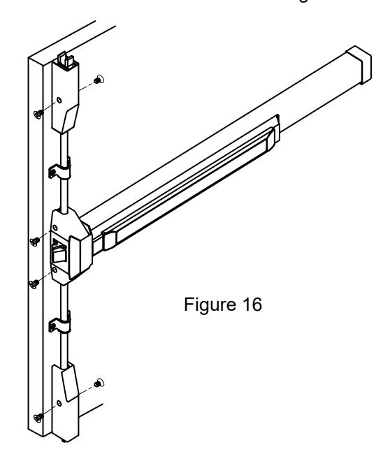
- 2. Install the chassis cover, end cap and the top & bottom latch covers.
- 3. Install the two rod guides into position over the rods as shown in Figure 16.
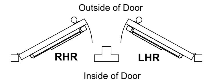
DOOR HANDING
Use the diagram to determine the hand of door.
NOTE:
Electrically dogging the device during high traffic hours of the day will greatly extend the life of this device.
Electric Dogging:
Providing constant power of 24VDC to the ELR will keep the push bar depressed and the latch retracted.
Release Electric Dogging:
De-energizing the ELR will release the push bar. The push bar will return to the detracted position and the latch will extend to lock door.