S4100 RIM Installation Instructions
Open the original PDF document
View PDF

[t] 800.413.8783 ■ 805.494.0622 ■ E-mail: service@sdcsecurity.com ■ 801 Avenida Acaso, Camarillo, CA 93012 ■ PO Box 3670, Camarillo, CA 93011
INSTALLATION INSTRUCTIONS
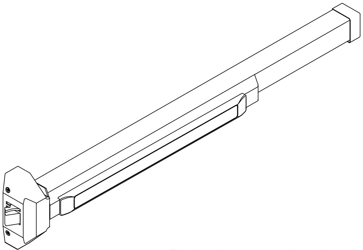
S4100 RIM PANIC / FIRE EXIT DEVICE
These instructions are presented in step by step sequence. Use the provided templates to tape to your door and frame as an aid to prepare in mounting the device.
Please read instructions thoroughly before installing.


[t] 800.413.8783 805.494.0622 E-mail: service@sdcsecurity.com 801 Avenida Acaso, Camarillo, CA 93012 PO Box 3670, Camarillo, CA 93011
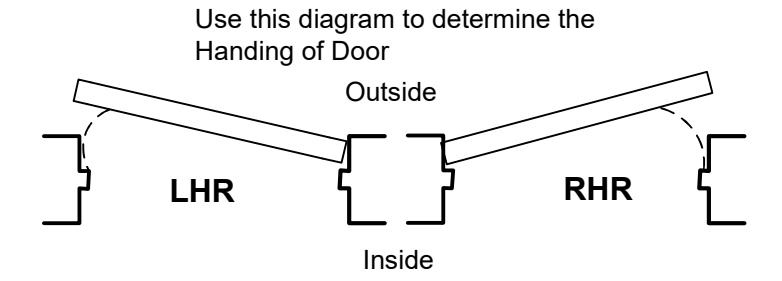
DOOR HANDING

DOOR APPLICATIONS
SINGLE DOOR
Use a Standard Rim Strike
DOUBLE DOOR WITHOUT MULLION
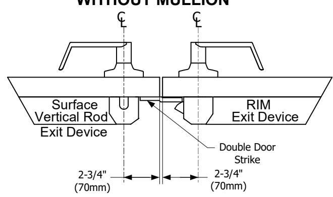
One Double Door Strike must be used for this combination
DOUBLE DOOR WITH MULLION
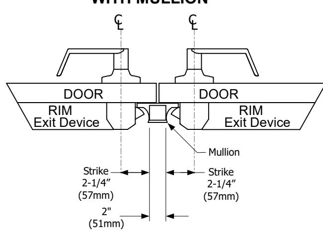
NOTE: Use the Mullion Strike & Strike Hook instead of a standard Rim Strike if two Rim Fire Exit Devices are installed with the Fire Rated Mullion.

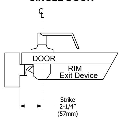
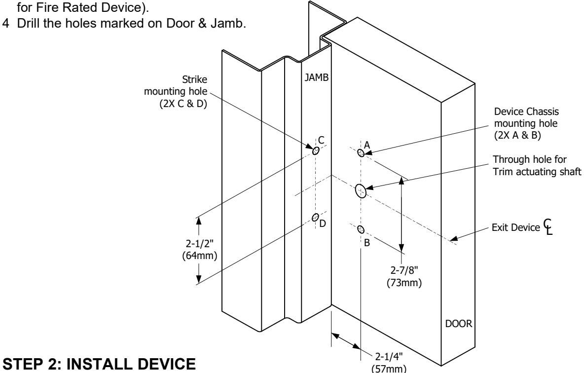
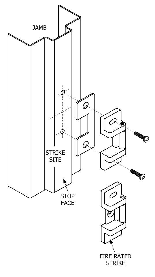
STEP 1: MARK AND DRILL MOUNTING HOLES
- 1 Mark a center line of the exit device on the door by drawing a line across the door at 40" above the finished floor as shown on the image below.
- 2 Use the template and align the center lines from the template with the center lines marked on the door & stop. Mark the location of the two Exit Device mounting holes.
3 With the folded Template against the stop, mark the location of the two Strike mounting holes (three mounting holes for Fire Rated Device).
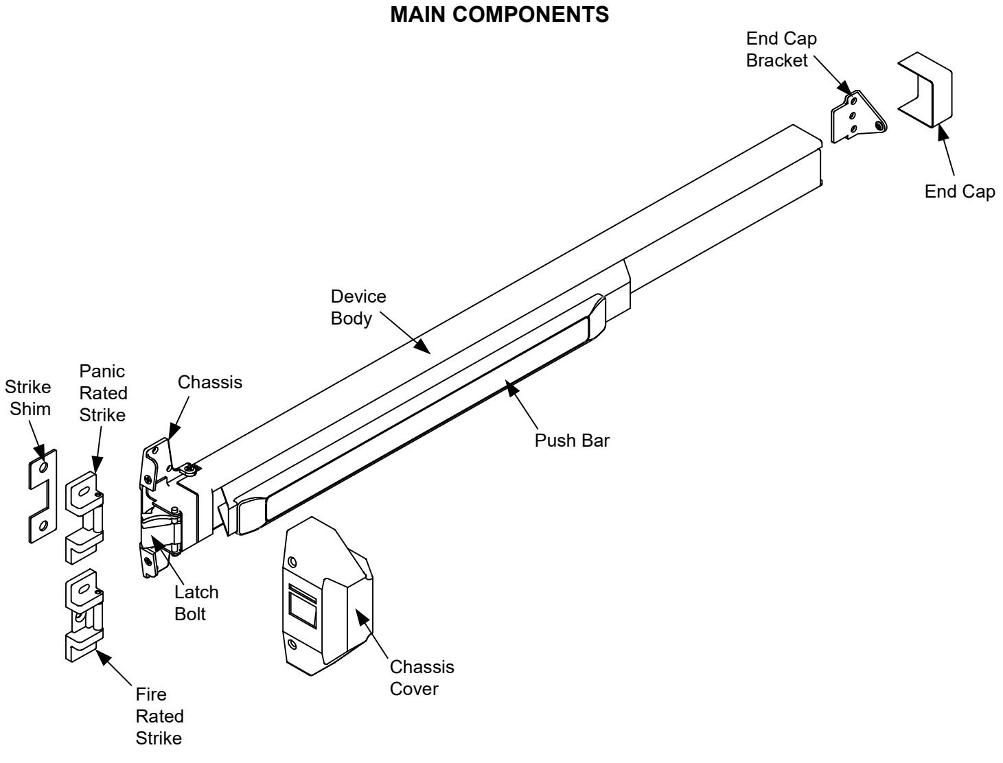
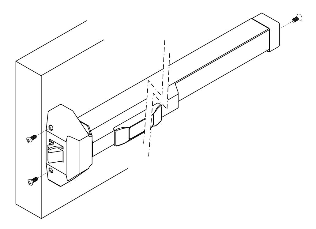
A. Device Body Installation
- 1. Remove Chassis cover from Device chassis. Attach Device Body horizontally to the drilled holes by using the supplied mounting screws.
- 2. If using Trim, be sure to line up the Trim Actuating Shaft (Tailpiece) with the cam located on the back of the Device chassis. For details refer to the Trim Installation Instructions & Template.
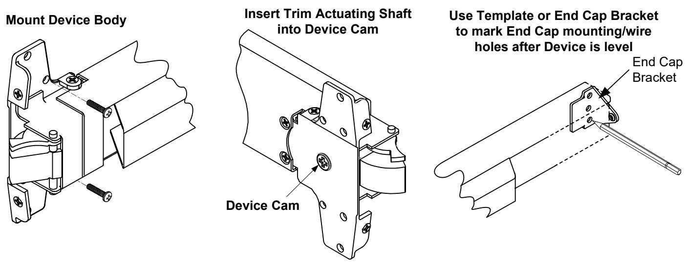
B. End Cap Installation
- 1. Remove End Cap from End Cap Bracket. Use the Template (or the End Cap Bracket) to mark hole locations.
- 2. Drill and tap two mounting holes and drill one wire through hole. Install the End Cap & End Cap Bracket.

STEP 3: INSTALL STRIKE
- Attach the strike to the stop at the drilled holes using the supplied mounting screws.
- 2. Open & close door to verify Latch Bolt & Dead Latch are aligned properly.
- 3. Adjust Strike if it is too tight or loose before tightening screws.
- 4. Once Strike is adjusted, install center screw (for Fire Rated Strike only).
NOTE:
For Panic Rated Rim Exit Devices;
A 1/8" shim is provided for doors with a 1/2" stop (The shim is not required for doors with a 5/8" stop).
STEP 4: WIRING THE ELR (Electric Latch Retraction)
1. Using a 24VDC regulated power supply, wire the (+) RED wire lead from the device to the (+) positive side of power source. Wire the (-) BLACK wire lead from the device to the (-) negative side of the power source.
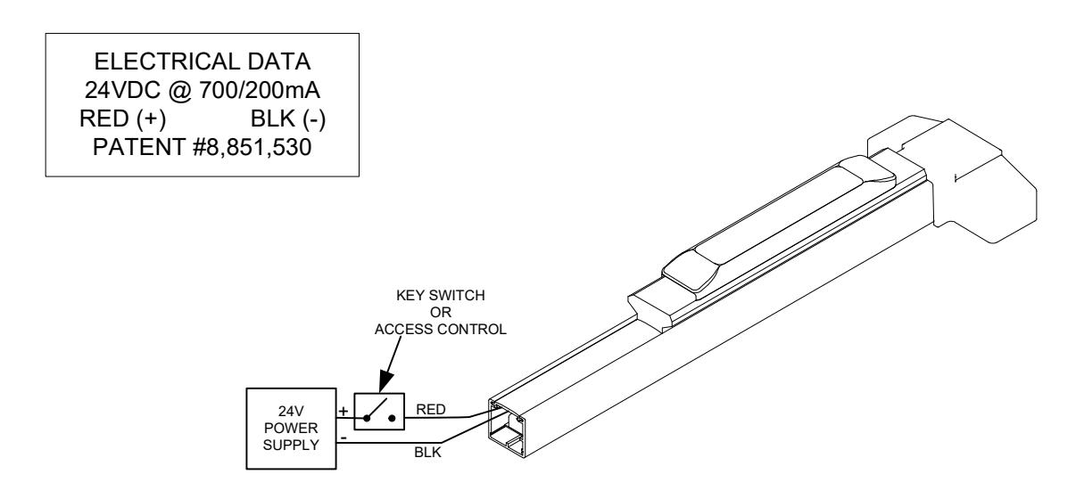
2. Apply power to the ELR and cycle the unit to verify that it is retracting both the push pad and latch.

STEP 4: INSTALL COVERS
-
1. Test Push Bar operation before installing cover
- a) NO TRIM; The door can be opened smoothly when Push Bar is depressed.
- b) WITH TRIM; The door can be opened smoothly when key or lever is operated.
- 2. Install Chassis Cover & End Cap with supplied screws.
NOTE:
Electrically dogging the device during high traffic hours of the day will greatly extend the life of this device.
Electric Dogging:
Providing constant power of 24VDC to the ELR will keep the push bar depressed and the latch retracted.
Release Electric Dogging:
De-energizing the ELR will release the push bar. The push bar will return to the detracted position and the latch will extend to lock door.