Roton Installation Instruction RETW – 75009010-Rev-011819
Open the original PDF document
View PDF

ROTON INSTRUCTION SHEETPART NO: 75009010 Removable Electric for Concealed hinges – RETW Rev: 01.18.19
HAGER Companies, 139 Victor Street, St. Louis, MO 63104 (800) 325-9995
REMOVABLE ELECTRIC THROUGH WIRE
Door and Frame Preparation
- 1. For grout filled frame, install a Mortar Box (HAGER 430). Failure to do so will void the hinge warranty.
- 2. Prepare the door and frame for installation using the standard installation instruction sheet furnished with the hinge.
Installation
- 1. Attach the hinge to the door and frame using the standard installation instruction sheet furnished with the hinge.
- 2. If the door will have a closer on it, disconnect the closer arm. The module is much easier to install with the door fully open.
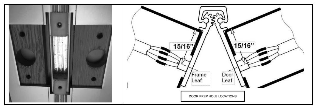
- 3. Place the marking template into the notched section of the hinge. Make sure it rests flat against the mounting surface and to the outside edge of the hinge.
- 4. Using the transfer punch, center punch both the mounting holes and the wire access hole. See Fig. 1. The middle hole is the wire access hole.
- 5. Repeat steps 2 and 3 for the opposite leaf of the hinge.
- 6. Drill only the 5/8" (3/4" max. for Quick Connect) diameter access hole in both the frame rabbet and the door edge. For metal frames and doors ≤ 0.110" (2.8mm)
thick, it is not necessary to drill pilot holes for the mounting screws, if using the self-drilling screws provided. For metal frames and doors > 0.110" (2.8mm) thick, drill the pilot holes for the mounting screws using a #16 (0.177"/4.5mm) bit, if using the self-drilling screws provided. For wooden doors, drill pilot holes for the mounting screws using a #18 (0.170"/4.3mm) bit, if using the wood screws provided.
- 7. After drilling, remove any burrs or sharp edges from the holes to prevent damage to the wire leads.
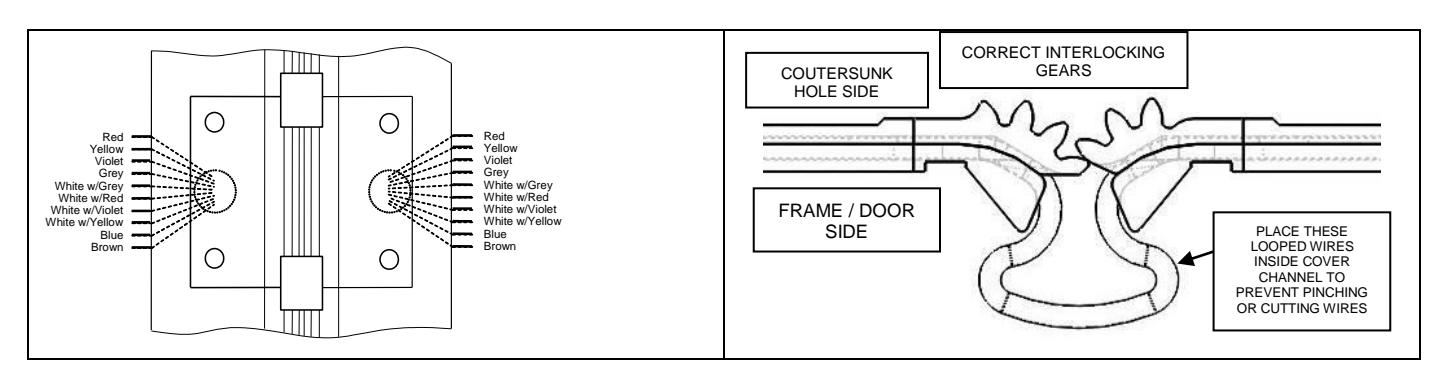
- 8. Identify which leaf gears of the module matches the frame leaf of the installed hinge (the number of gear teeth are different on the frame and door leafs).
- 9. Connect the system wires from the frame to the appropriate leads of the frame leaf side of the module (as described in the system wiring diagram). Insulate the bare end of any unused wires.

screws provided.
ROTON INSTRUCTION SHEETPART NO: 75009010 Removable Electric for Concealed hinges – RETW Rev: 01.18.19
HAGER Companies, 139 Victor Street, St. Louis, MO 63104 (800) 325-9995
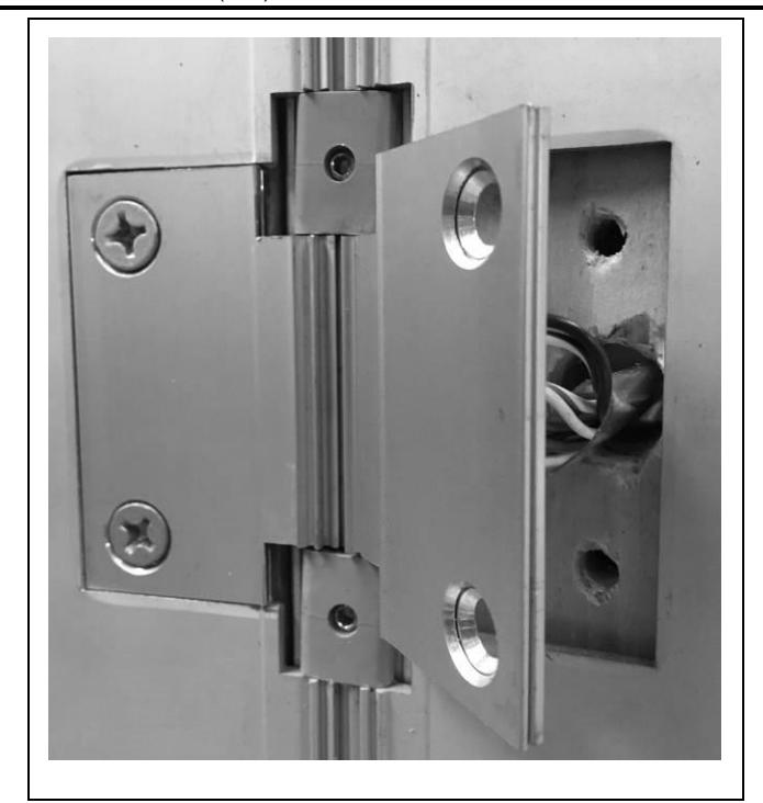
- 10. Insert the frame leaf module into the notch of the hinge while carefully pushing the wires back through the access hole in the frame, making sure they are placed so they will not be cut or pinched as the installation is completed. Attach the module to the frame, leaving the screws slightly loose. For metal doors, use the #12 selfdrilling screws provided (recommended driver speed 1,900-2,500 RPM). For wood doors, use the #12 wood
- 11. Connect the system wires from the door to the appropriate leads of the door leaf side of the module. See illustration to the right. Insulate the bare end of any unused wires.
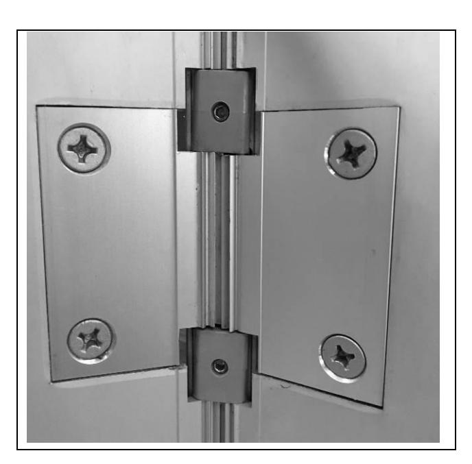
- 12. Insert the door leaf module into the notch of the hinge while carefully pushing the wires back through the access hole in the door, making sure they are placed so they will not be cut or pinched as the installation is completed. Move the door to at least 90 degrees to verify the gears align with the gears in the frame leaf. Make sure the gears you can see are aligned with the other hinge gears above and below. Using the #12 self-drilling screws to attach the module to the door, ensure the proper interlock of gear teeth of the two module components and that the looped wires are placed into the cover channel.
- 13. Tighten all screws in the module, making sure that both leaves of the module are flat and flush with the hinge leaves. A quick visual inspection should show all gears are vertically aligned. Cycle door open and closed to ensure proper alignment with hinge and module.
- 14. Reattach door closer arm if present.
MAXIMUM ELECTRICAL RATING CONTACT THROUGH WIRE
Volts: 48V DC/AC Amperes: 3.5Amps Continuous