Roton Installation Instruction ETW – 75009017-Rev-032019
Open the original PDF document
View PDF

ROTON ELECTRIC MODIFICATION PART NO: 75009018 ROTON MODEL: 780-057 and 780-157 REVISION: 03/20/19
HAGER Companies, 139 Victor Street, St. Louis, MO 63104 (800) 325-9995
ETW – Electric Through Wires
Door and Frame Preparation
For grout filled frame, install a Mortar Box (HAGER 430). Failure to do so will void the hinge warranty.
- 1. Prepare the door and frame using the standard installation instruction sheet furnished with the hinge, but do not attach the hinge at this time.
- 2. Drill a 1/2" (5/8" max for Quick Connects) diameter access hole in both the frame rabbet and the door face for a Full Surface hinge at the proper location for the wire leads. Use table provided for correct location.
- 3. After drilling, deburr the holes to prevent damage to the wire leads.
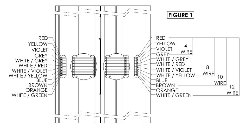
- 4. Connect the system wires from the frame to the appropriate leads of the hinge frame leaf (as described in the system wiring diagram). See Figure 1. Insulate the bare end of any unused wires.
- 5. Carefully slide the wires back through the access hole in the frame making sure they are placed so they will not be cut or pinched as installation is completed. Attach the hinge to the frame per the standard installation instruction sheet supplied with the hinge.
- 6. Position the door at 90 degrees to the frame and connect the system wires from the door to the appropriate leads of the hinge door leaf. See Figure 1. Insulate the bare end of any unused wires.
- 7. Carefully slide the wires back through the access hole in the frame making sure they are placed so they will not be cut or pinched as installation is completed. Attach the hinge to the frame per the standard installation instruction sheet supplied with the hinge.
- 8. Install the molding per the installation instructions that came with the hinge.

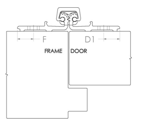
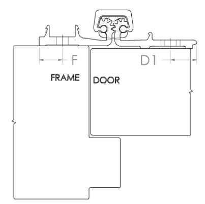
| TABLE | |||
|---|---|---|---|
|
HINGE
MODEL |
TYPE | F | D1 |
| 780-057 Full Surface | 1/2" | 1/2" | |
| 780-157 Full Surface | 7/16" | 1/2" | |
MAXIMUM ELECTRICAL RATING CONTACT
Volts: 30V dc/ac Amperes: 3.5A Continuous 16A Pulse (300ms)
Recommended: For current ratings greater than 1.0A, use two or more wires in parallel. Make sure same colored wires are connected properly on both sides of hinge.

ROTON ELECTRIC MODIFICATION PART NO: 75009018 ROTON MODEL: 780-057 and 780-157 REVISION: 03/20/19
HAGER Companies, 139 Victor Street, St. Louis, MO 63104 (800) 325-9995
RETW – Removable Electric Through Wires
Door and Frame Preparation
For grout filled frame, install a Mortar Box (HAGER 430). Failure to do so will void the hinge warranty.
- 1. Prepare the door face and frame for installation using the standard installation instruction sheet furnished with the hinge.
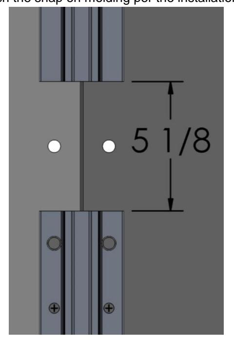
- 2. Attach the top and bottom part of the hinge to the frame and door per the installation instructions that came with the hinge. Make sure to align the top and bottom hinge sections correctly. Leaving 5.125" in between hinge sections for the removable module.
- 3. If the door will have a closer on it, disconnect the closer arm. The module is much easier to install with the door fully open.
- 4. Drill only the 5/8" (3/4" max. for Quick Connect) diameter access hole in both the frame rabbet and the door face at the RETW location.
- 5. Remove any burrs or sharp edges from the holes to prevent damage to the wire leads.
- 6. Identify which leaf gears of the module matches the frame leaf of the installed hinge (the number of gear teeth are different on the frame and door leaves).
- 7. Connect the system wires from the frame to the appropriate leads of the frame leaf side of the module (as described in the system wiring diagram). Insulate the bare end of any unused wires.
- 8. Position module on the frame. Align the edge of the leaf and cover channel. Install screws and leave loose.
- 9. Connect the system wires from the door to the appropriate leads of the door leaf side of the module. Insulate the bare end of any unused wires.
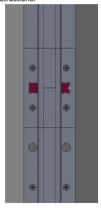
- 10. Insert the door leaf module by aligning the edge of the module to the upper hinge and align the cover channel. Attach the module to the door, leaving the screws slightly loose.
- 11. Tighten all screws in the module, making sure that both leaves of the module are flat and flush with the hinge leaves. A quick visual inspection should show all gears are vertically aligned. Cycle door open and closed to ensure proper alignment with hinge and module.
- 12. Reattach door closer arm if present.
- 13. Attach the snap on molding per the installation instructions.