Roton 780-210HD Specifications
Open the original PDF document
View PDF

780-210HD
Full Surface Heavy Duty
Applications
Can be used with any door and frame material Security moldings 1/32" (1 mm) inset
PRODUCT SPECIFICATIONS
For more information visit www.hagerco.com


PRODUCT SPECIFICATIONS
Clearance:
1/32" (1 mm) minimum recommended for hinge side Plus standard lockside clearance 1-5/8" (41 mm) minimum frame face required plus 3/16" (5 mm) rotational clearance
Door Reinforcement:
None required
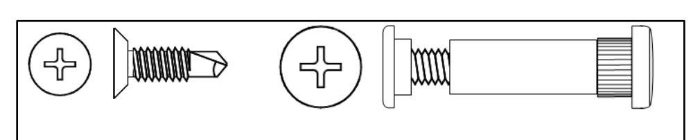
Fasteners:
Standard: 1/4-20 x 1-1/4" Sexbolt (fastener + Post) Standard: Dril-Kwik® – #12-24 X 11/16" Flat Head Screws
Additional Options Available upon request
Features:
Standard duty for medium frequency doors. Heavy duty for high frequency doors or heavy, medium frequency doors. Can be used with any door and frame material Security molding 1/32" (1 mm) inset
Finishes:
CLR, DBZ, BLK
Fire Rating:
Up to 3-hour metal and 90 minute wood composite (with studs)
Frame Reinforcement:
None required to 200 lbs. Heavier weight use 16-gauge channel.
Length:
79", 83", 85", 95", 119"
Length Options:
Standard and Custom
Material:
Aluminum 6063-T6
Options:
Hospital Tip
TIPIT® (see Roton accessories)
Warranty:
All Roton products have a lifetime warranty. When ordering electric Roton, the electric portion of the hinge has a one-year warranty.

REVISION: 04/01/17

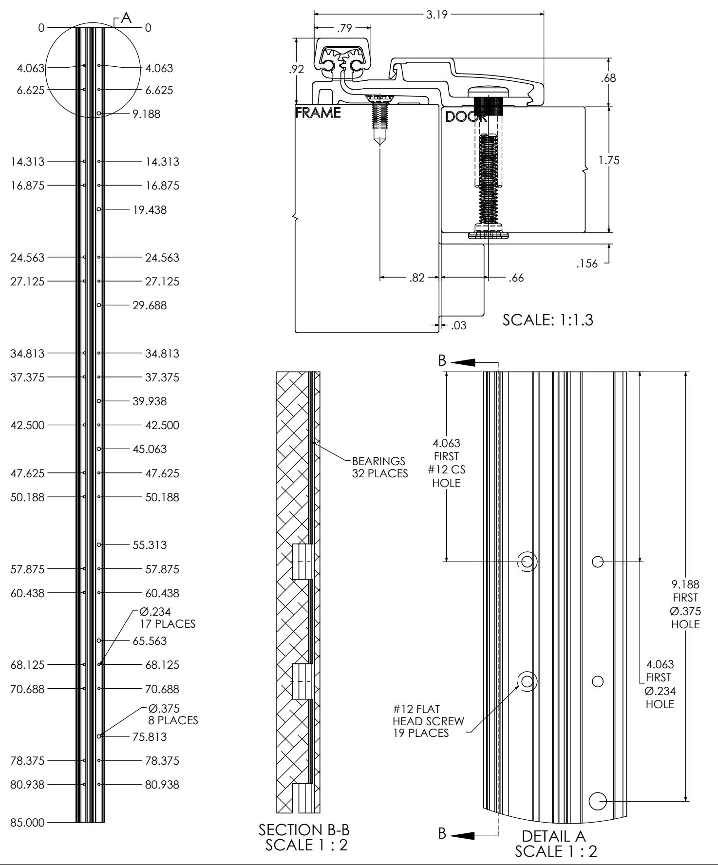
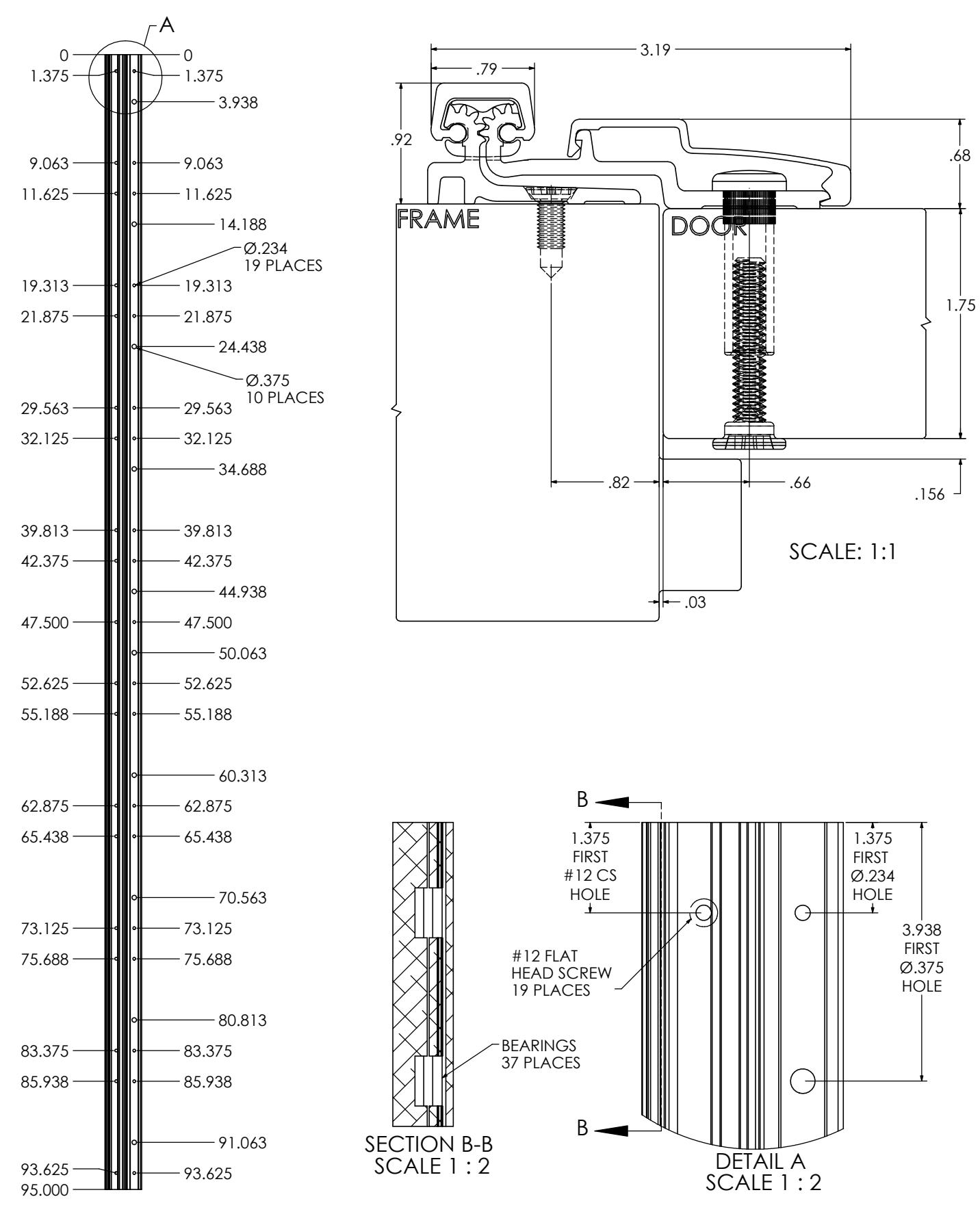
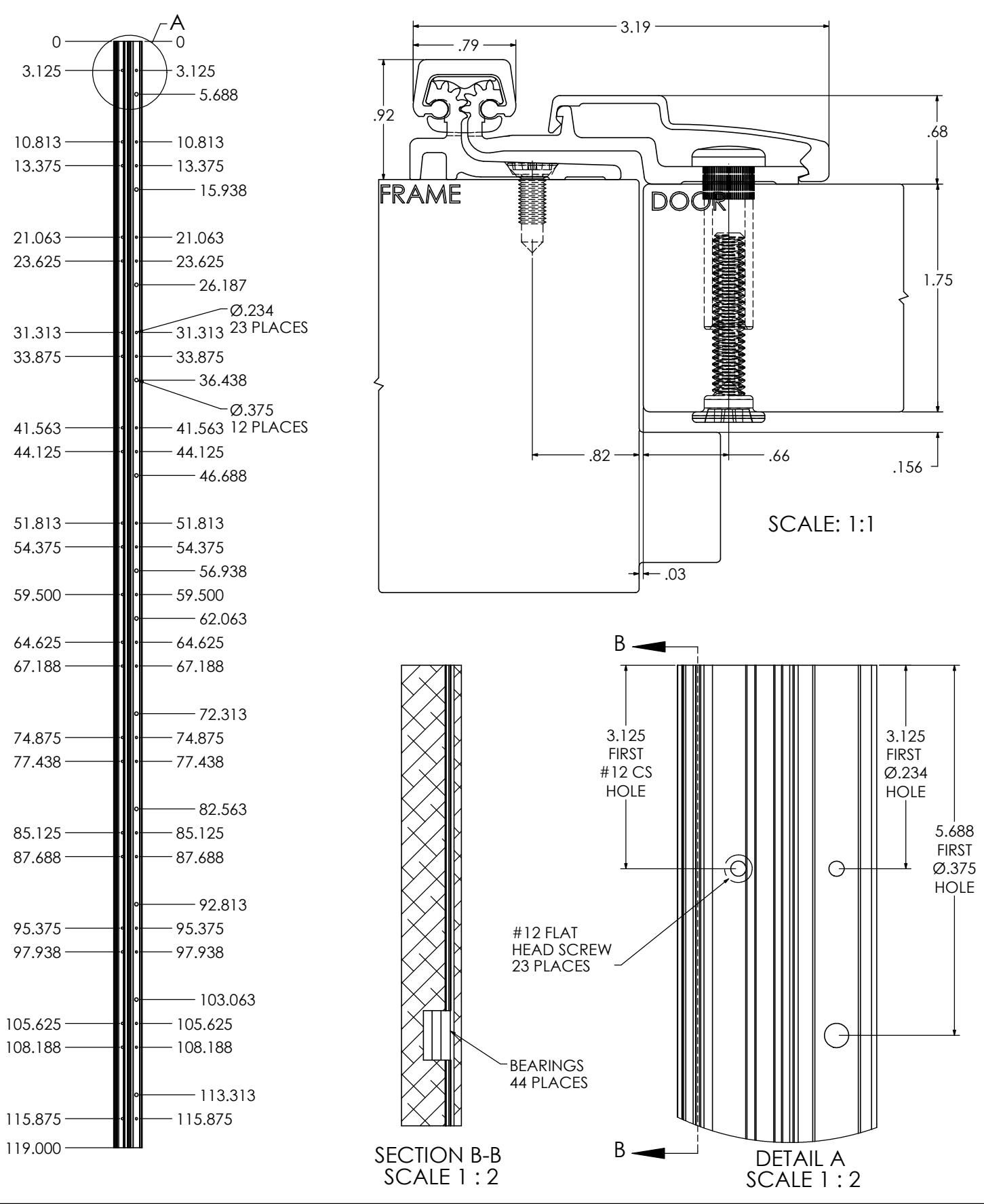
TEMPLATE FOR FULL SURFACE CONTINUOUS GEARED ALUMINUM HINGE
OU-Z I U-П D-O3 REVISION: 04/01/17

REVISION: 04/01/17

REVISION: 04/01/17
REVISION: 04/01/17

ROTON INSTRUCTION SHEET PART NO: 75007210 ROTON MODEL: 780-210 REVISION: 05/18/16
HAGER Companies, 139 Victor Street, St. Louis, MO 63104 (800) 325-9995
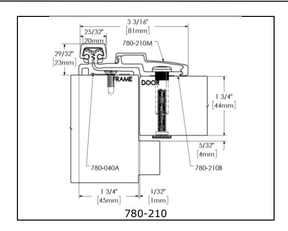
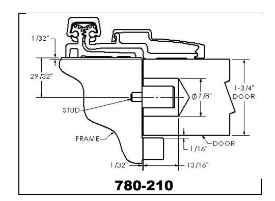
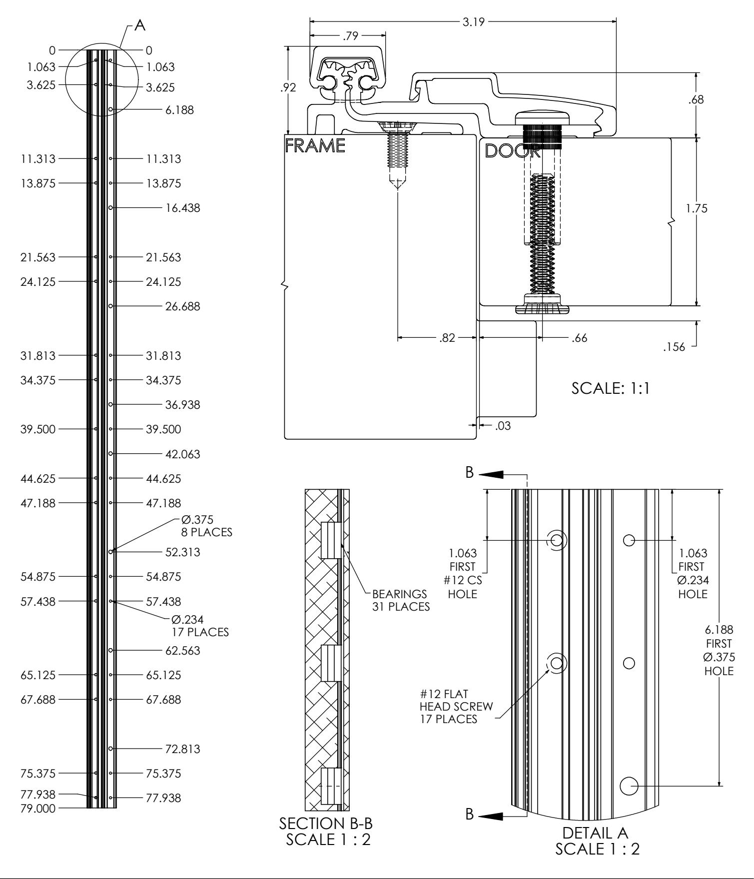
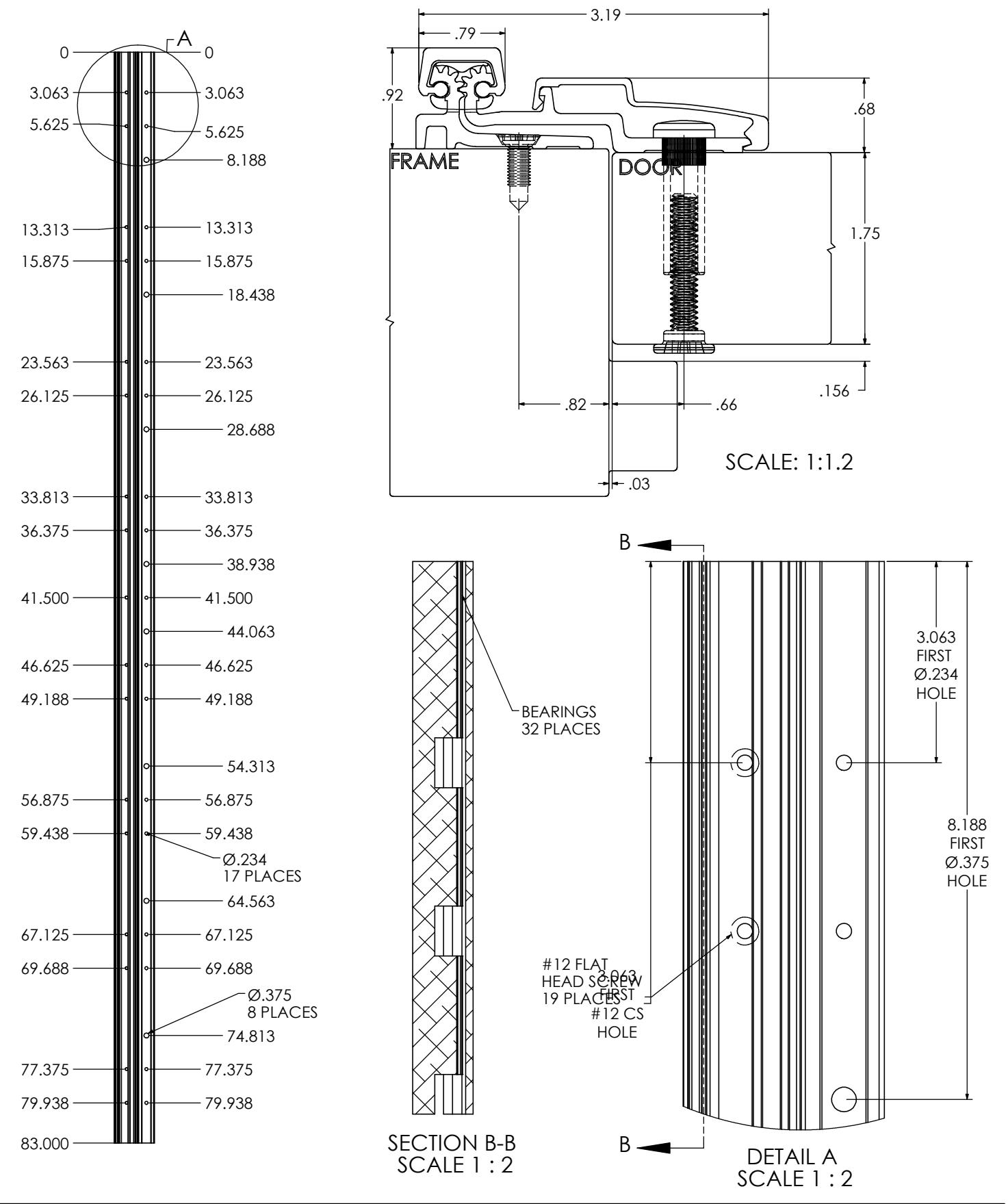
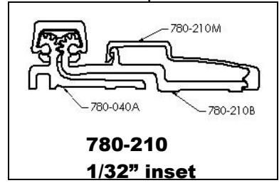
ROTON Model 780-210 is an Aluminum Continuous Geared Full Surface Hinge that provides a 1/32" door inset. It can be used with any standard frame without hinge preps, and either with or without reinforcements depending on door weight. The frame face must have a flat surface at least 1-5/8" wide. Minimum clearance between the hinge edge of the door and the frame rabbet is 1/32" (1mm). "HD" models have additional bearings for heavy-duty application.
Hinge Length
All ROTON Hinges are supplied approximately 1" shorter than the nominal door height to avoid threshold or carpet clearance problems. If the hinge must be trimmed shorter, first determine the correct hand of the door and orientation of the hinge. Then mark and trim from the bottom of the hinge only – do not cut from the top end.
| NOM. | NOM. HINGE | NUMBER OF | |
|---|---|---|---|
| DOOR | LENGTH | FASTENERS | |
| HEIGHT | (FRAME / | ||
| DOOR | |||
| 6' 8" | 79" (2006mm) | 17 / 25 | |
| 7' 0" | 83" (2108mm) | 19 / 27 | |
| 7' 2" | 85" (2159mm) | 19 / 27 | |
| 8' 0" | 95" (2413mm) | 19 / 29 | |
| 10' 0" | 119" (3022mm) | 23 / 35 | |
TOTAL 7/16" (11.2mm)
(1/8" typ.)
Total Clearance Between Door And Frame Width
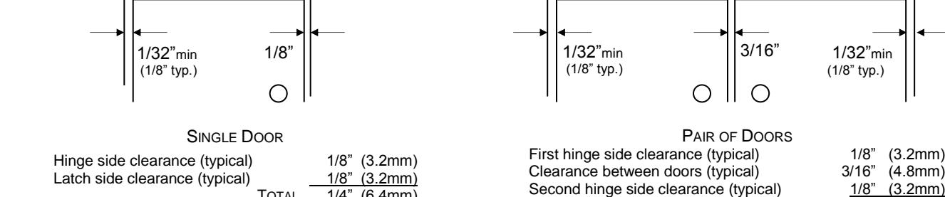
TOTAL 1/4" (6.4mm)
General Fitting Procedure
- For new construction with metal doors/frames: See the clearance information above to attain the proper door/frame size. A minimum clearance of 1/32" (0.8mm) is required between the hinge edge of the door and the frame rabbet. Mortar guards, either Styrofoam or wood, are recommended for frames to prevent grout from interfering with the installation of the hinge fasteners.
- For new site-hung wood doors: If necessary, scribe and cut from the latch edge of the door to leave sufficient hinge stile thickness for proper fastening. See the clearance information above to attain the proper finished width of the door. A minimum clearance of 1/32" (0.8mm) is required between the hinge edge of the door and the frame rabbet.

ROTON INSTRUCTION SHEET PART NO: 75007210 ROTON MODEL: 780-210 REVISION: 05/18/16
HAGER Companies, 139 Victor Street, St. Louis, MO 63104 (800) 325-9995
Installation Procedure
Frame Preparation (See Fig. 1)
- 1. The frame face must have a flat surface at least 1-5/8" wide to support the hinge. Mark a line on the frame face 1-3/4" from the center of the gap between the door and jamb. For a typical 1/8" hinge side gap, the line will be 1-3/4" from the center of the gap.
- 2. Place the outer edge of the hinge frame leaf on this mark, with the top of the hinge positioned 1/16" (1/8" maximum) below the level of the header rabbet. Note: A 1/16" shim is recommended due to initial settling of the bearings.
- 3. Rotate the door hinge leaf out of the way, to make it accessible to mark and center punch the screw hole locations. Accurate location is important for proper installation.
- 4. For metal frames 12 gage or less (≤ .110"/2.8mm), it is not necessary to pre-drill pilot holes if using the self-drilling screws provided. For metal frames larger than 12 gage (> .110"/2.8mm), drill and tap all mounting holes for #12-24 threads prior to installing the screws. For wood frames, pre-drill pilot holes using a #18 (.170"/4.3mm) bit for optional #12 wood screws.
- 5. Attach the hinge to the frame face. For metal frames, use the #12 self-drilling screws provided (recommended driver speed 1,900-2,500 RPM). For wood frames, use optional #12 wood screws.
Door Preparation
- 1. Rotate the hinge leaf out of the way and set the door into the frame, using shims or wedges to adjust for the desired clearance on all sides.
- 2. Allow an additional 1/32" of clearance on the latch edge of the door at the top only. This will allow for any settling or twisting of the frame that may occur after the shims are removed and the weight of the door is transferred entirely to the frame.
- 3. Allow 1/16" clearance between the top of the door and the frame header rabbet. A good method for this is to use a 1/16" thick shim placed over the top edge of the door.
- 4. With the door held securely in place, rotate the hinge leaf into position on the face of the door.
-
5. (Standard sexbolt mounting) Mark and center punch the locations of the larger 3/8" diameter holes.
Accurate location is important for proper installation.
Rotate the hinge leaf back out of the way. At each mark, drill a hole completely through the door using a 3/8" (9.5mm) bit.
- (Optional mounting without sexbolts) Mark and center punch the locations of the smaller 15/64" diameter holes. For metal doors, use optional #12 self-drilling screws. For wood doors, pre-drill pilot holes using a #18 (.170"/4.5mm) bit for optional #12 wood screws.
Hanging the Door (See Fig. 2)
- 1. Attach the hinge to the door as shown. Sexbolts may be reversed if additional security is needed on the push face of the door, but once the molding is in place reversed sexbolts cannot be accessed for maintenance or removal.
- 2. Remove all shims and wedges and make a gentle trial swing. Carefully check the door for proper swing and clearance.
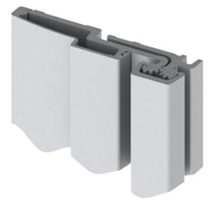
Install the Snap-On Molding (See Fig. 3)
1. For the door leaf – Locate and loosen the retaining setscrew on the edge of the molding with the 5/64" hex key provided. Hook the thicker leg of the molding under the outside edge of the door leaf along the full length of the hinge. Starting at the top and working downward, press or gently tap the opposite leg of the molding in place (if necessary use a rubber mallet or wood block under a hammer, taking care not to damage the molding). Tighten the retaining setscrew.
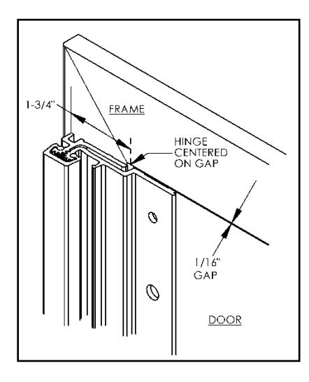
Fig. 1
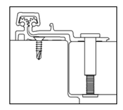
Fig. 2
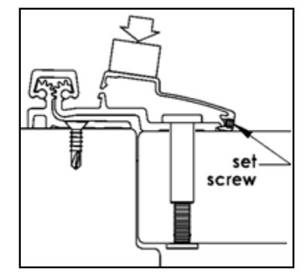
Fig. 3

ROTON INSTRUCTION SHEET PART NO: 75007210 ROTON MODEL: 780-210 REVISION: 05/18/16
HAGER Companies, 139 Victor Street, St. Louis, MO 63104 (800) 325-9995


| • | -8 . 5 — | ||
|---|---|---|---|
| 1.8 | 1000 | naev | |
| I |

ROTON UL FIRE–RATED STUDS PART NO: 75006030 ROTON MODEL: 780-210 REVISION: 05/31/17
HAGER Companies, 139 Victor Street, St. Louis, MO 63104 (800) 325-9995
ROTON Hinge U.L. Fire-Rated Studs – 780-210
These instructions outline how to install the optional stainless steel studs (4) for ROTON Hinge model 780-210. All four studs must be used in order to comply with U.L. requirements for composite wood fire doors rated up to 90 minutes and metal fire doors rated up to 3 hours.
Materials Needed
- Stainless steel studs (4).
- Drill, 7/8" diameter bit, #16 (.177") bit, 12-24 thread tap.
- #10 spanner screwdriver.
Installation
- 1. Install the hinge in accordance with the standard installation instructions furnished with the hinge.
- 2. On the door leaf, drill a 7/8 diameter by 13/16" deep. Drill hole in the center of the door edge, using the chart below to locate the holes. The first measurement is from the top of the hinge to the centerline of hole #1. The second, third and fourth holes are measured from centerline to centerline.
| Vertical Location | 79" | 83" | 85" | 95" | 119" |
|---|---|---|---|---|---|
| Hole #1 | 13-7/8" | 15-7/8" | 16-7/8" | 16-3/4" | 13-3/8" |
| Hole #2 | 10-1/4" | 10-1/4" | 10-1/4" | 20-1/2" | 30-3/4" |
| Hole #3 | 30-3/4" | 30-3/4" | 30-3/4" | 20-1/2" | 30-3/4" |
| Hole #4 | 10-1/4" | 10-1/4" | 10-1/4" | 20-1/2" | 30-3/4" |
- 3. Using the face of the frame as the reference point to locate the holes, drill and tap four (4) holes in the frame rabbet in the same vertical locations as the above chart. The horizontal location is 1/32"plus ½ of the door thickness.
- 4. Insert a stud into each of the four #12-24 threaded holes on the frame and tighten securely using a #10 spanner screwdriver.
- 5. Close the door slowly to assure that the studs are properly aligned. Any minor interference can be corrected using a rat-tail file.