Roton 780-113HD Specifications
Open the original PDF document
View PDF

780-113HD
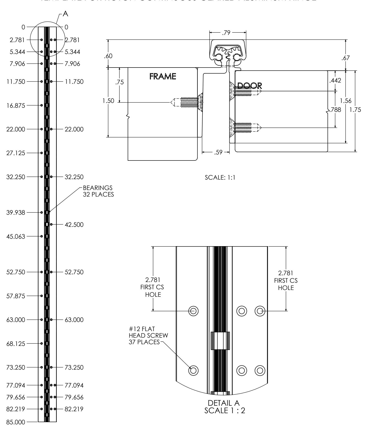
Heavy Duty Concealed Leaf Hinge
Application:
- "Safety Hinge" for kindergartens, nursing homes, daycares, etc. (when used without frame stop)
- Door leaf alignment rib for proper door location
- 1/16" (1.5 mm) inset


PRODUCT SPECIFICATIONS
CLEARANCE:
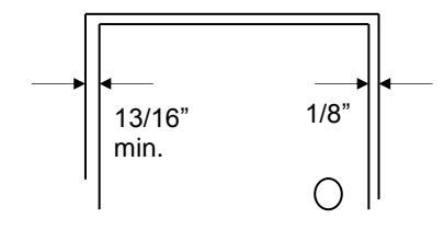
- 13/16' (21 mm) hinge side
- Plus standard lockside clearance
FASTENERS:
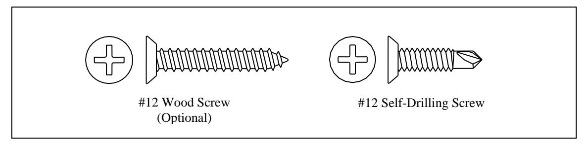
- #12-24 X 11/16" Flat Head Self-Drill Screws
LENGTH OPTIONS:
- Standard and Custom
DOOR REINFORCEMENT:
- None required to 200 lbs. Heavier weight use 16-gauge channel.
FRAME REINFORCEMENT:
- None required to 200 lbs. Heavier weight use 16-gauge channel.
WARRANTY:
- All Roton products have a lifetime warranty. When ordering electric Roton, the electric portion of the hinge has a one-year warranty.
MATERIAL:
- Aluminum 6063-T6
OPTIONS:
- Hospital Tip
EPD:
- Roton Continuous Hinges Environmental Product Declaration
PRODUCT SIZE OPTIONS
| LENGTH (INCHES) | LENGTH (MM) | HOLE COUNT (DOOR) | HOLE COUNT (JAMB) |
|---|---|---|---|
| 79 | 2007 | 15 | 16 |
| 83 | 2108 | 19 | 18 |
| 85 | 2159 | 19 | 18 |
| 95 | 2413 | 20 | 20 |
| 119 | 3023 | 23 | 26 |
REVISION: 04/22/16
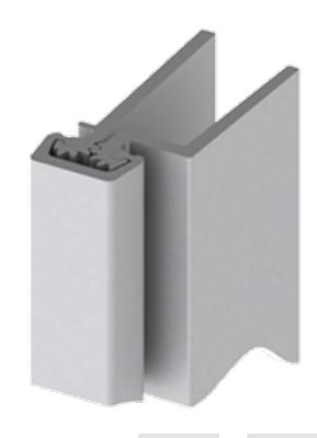
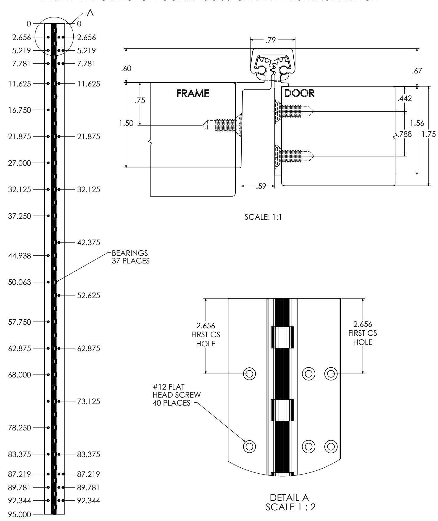
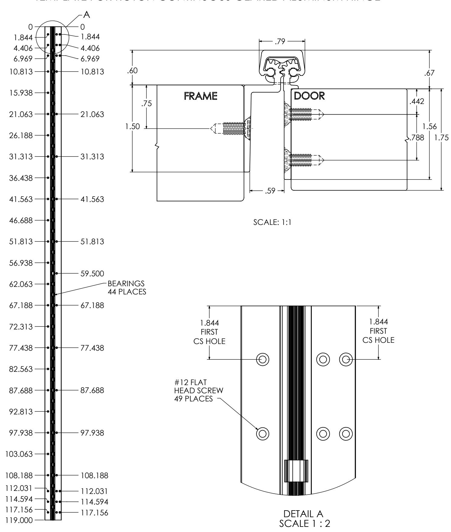
TEMPLATE FOR ROTON CONTINUOUS GEARED ALUMINUM HINGE
TEMPLATE FOR ROTON CONTINUOUS GEARED ALUMINUM HINGE
REVISION:
03/27/17
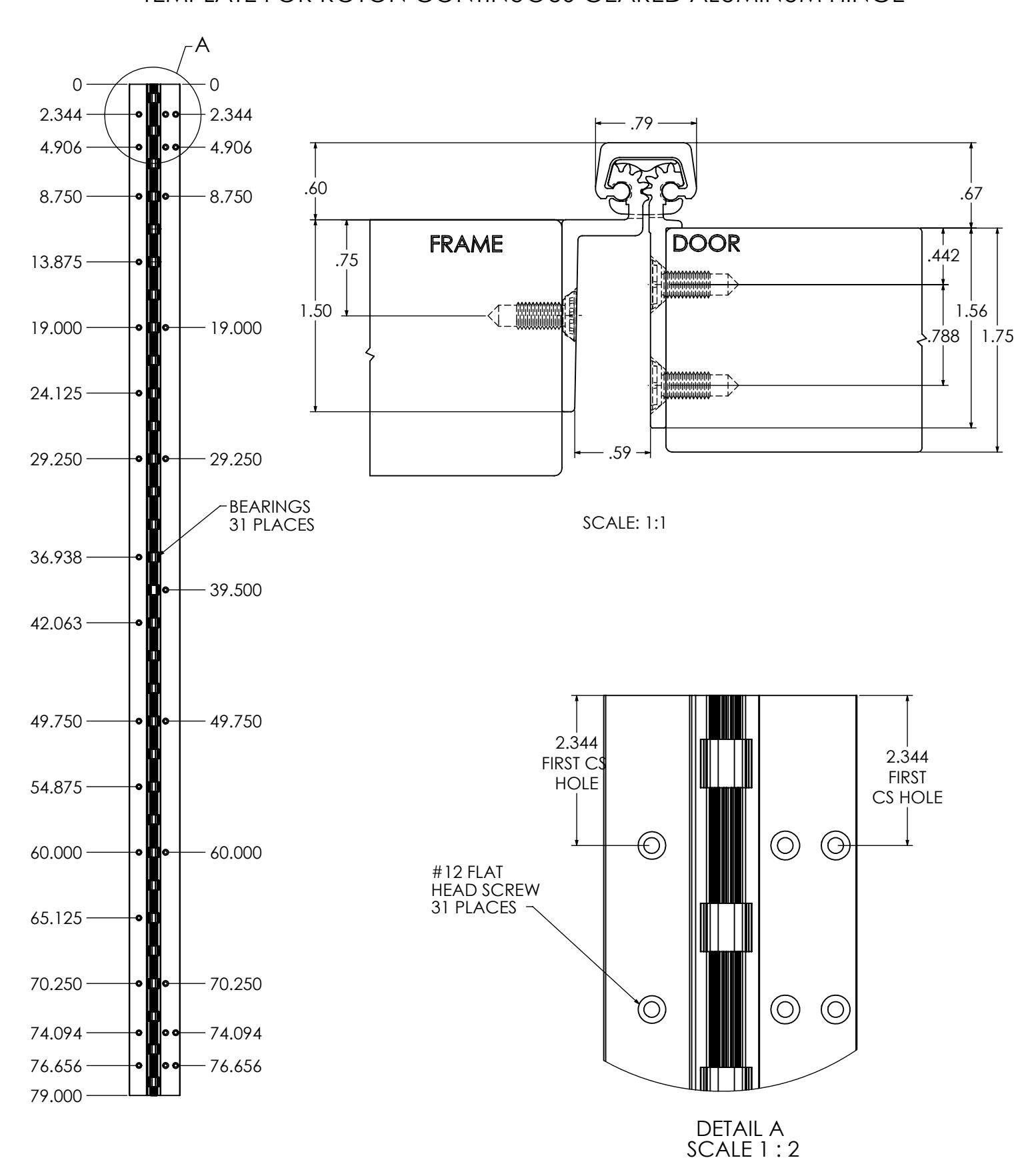
TEMPLATE FOR ROTON CONTINUOUS GEARED ALUMINUM HINGE
REVISION:
03/27/17
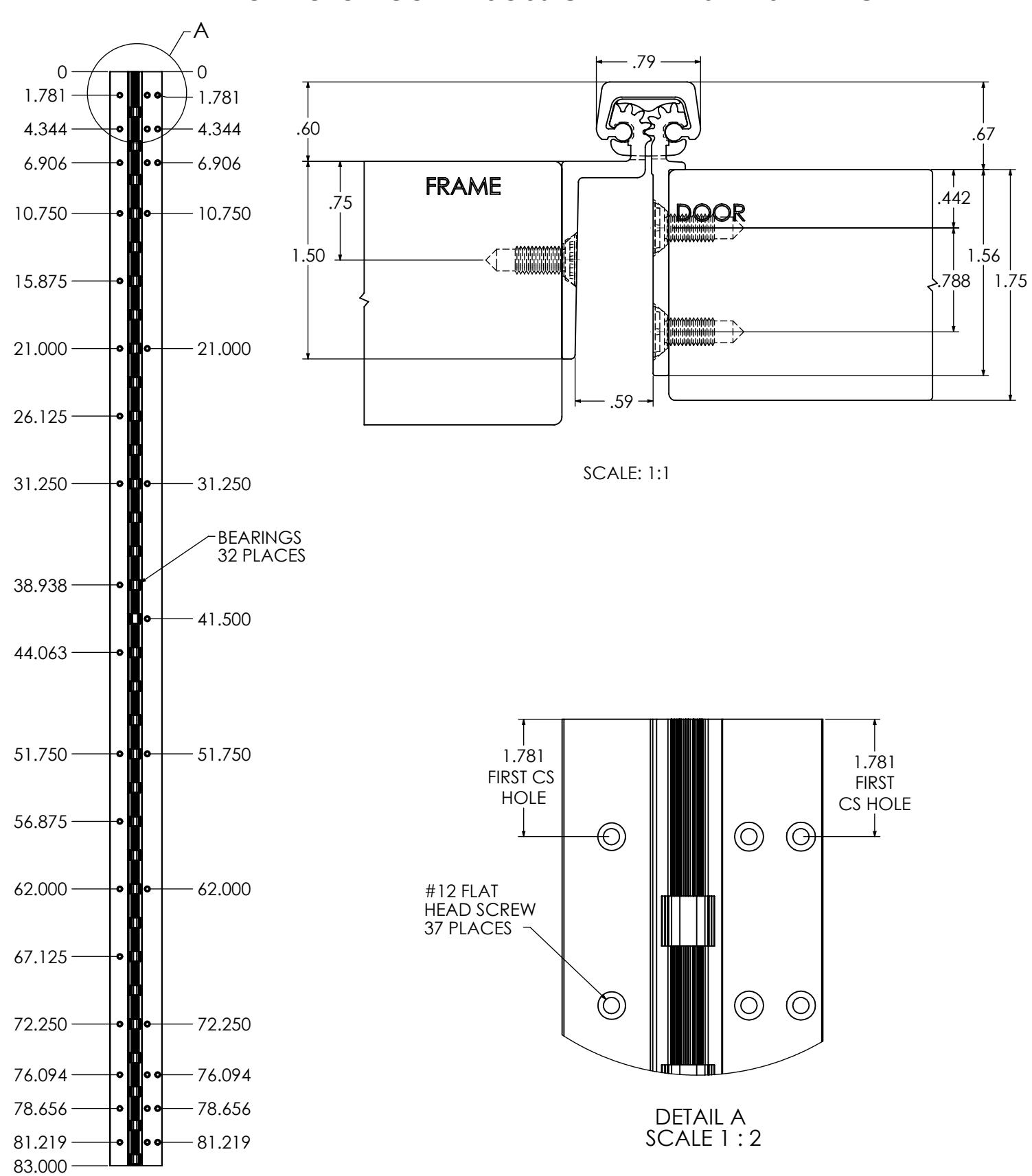
TEMPLATE FOR ROTON CONTINUOUS GEARED ALUMINUM HINGE
REVISION:
04/22/16
TEMPLATE FOR ROTON CONTINUOUS GEARED ALUMINUM HINGE
REVISION:
04/22/16

ROTON INSTRUCTION SHEET PART NO: 75007113 ROTON MODEL: 780-113 REVISION: 05/18/16
HAGER Companies, 139 Victor Street, St. Louis, MO 63104 (800) 325-9995
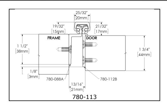
ROTON Models 780-113 is an Aluminum Continuous Geared Concealed Leaf Hinge. Clearance required between the hinge edge of the door and the frame is 13/16" (21mm). "HD" models have additional bearings and fasteners for heavy-duty application.
Hinge Length
All ROTON Hinges are supplied approximately 1" shorter than the nominal door height to avoid threshold or carpet clearance problems. If the hinge must be trimmed shorter, first determine the correct hand of the door and orientation of the hinge. Then mark and trim from the bottom of the hinge only – do not cut from the top end.
| NOM. | NOM. HINGE | NUMBER OF |
|---|---|---|
| DOOR | LENGTH | FASTENERS |
| HEIGHT | (FRAME / DOOR | |
| 6' 8" | 79" (2006mm) | 15 / 15 |
| 7' 0" | 83" (2108mm) | 18 / 19 |
| 7' 2" | 85" (2159mm) | 18 / 19 |
| 8' 0" | 95" (2413mm) | 20 / 20 |
| 10' 0" | 119" (3022mm) | 26 / 23 |
Total Clearance Between Door And Frame Width
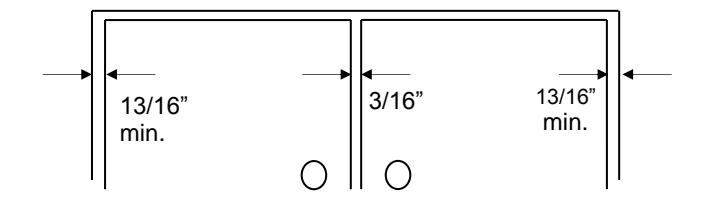
| SINGLE DOOR - SQUARE EDGED | ||
|---|---|---|
| Hinge thickness | 13/16" (21mm) | |
| Allowance for frame irregularities | 1/32" (0.8mm) | |
| Latch side clearance (typical) | 1/8" | (3.2mm) |
| TOTAL* | 31/32" (24.6mm) | |
PAIR OF DOORS - SQUARE EDGED First hinge thickness 13/16" (21mm) First allowance for frame irregularities 1/32" (0.8mm) Clearance between doors (typical) 3/16" (4.8mm) Second hinge thickness 13/16" (21mm) Second allowance for frame irregularities 1/32" (0.8mm) TOTAL* 1-7/8"(47.6mm)
* For doors that are pre-beveled 1/8"-in-2" on the hinge edge, add 1/32" (0.8mm) per door to the TOTAL clearance shown.
General Fitting Procedure
- For new construction with metal doors/frames: To accommodate the 13/16" (21mm) hinge clearance required for this ROTON model, order the door undersized or the frame header oversized. See the clearance information above to attain the proper size. Mortar guards, either Styrofoam or wood, are recommended for frames to prevent grout from interfering with the installation of the hinge fasteners.
- For new site-hung wood doors: If necessary, scribe and cut from the latch edge of the door to leave sufficient hinge stile thickness for proper fastening. A minimum clearance of 13/16" (21mm) is required between the hinge edge of the door and the frame. See the clearance information above to attain the proper finished width of the door.
- For remodeling with existing wood or laminate doors: If necessary, scribe and cut from the hinge edge of the door and plane smooth. A minimum clearance of 13/16" (21mm) is required between the hinge edge of the door and the frame. See the clearance information above to attain the proper finished width of the door. Installation Procedure.

ROTON INSTRUCTION SHEET ROTON MODEL: 780-113
HAGER Companies, 139 Victor Street, St. Louis, MO 63104 (800) 325-9995
PART NO: 75007113 REVISION: 05/18/16
Installation Procedure
Frame Preparation
- With the hinge open, place the hinge frame leaf against the frame making certain that the hinge face is in line and flush with the frame face along its entire length. Position the top of the hinge 1/16" (1/8" maximum) below the header. Note: A 1/16" shim is recommended due to initial settling of the bearings (See Fig. 1).
- 2. Mark and center punch the screw hole locations. Accurate location is important for proper installation.
- 3. For metal frames 12 gage or less (≤ .110"/2.8mm), it is not necessary to pre-drill pilot holes if using the self-drilling screws provided. For metal frames greater than 12 gage (> .110"/2.8mm), drill and tap all mounting holes for #12-24 threads prior to installing the screws. For wood frames, pre-drill pilot holes using a #18 (.170"/4.3mm) bit for optional #12 wood screws.
- 4. Do not attach the hinge to the frame at this time.
Door Preparation
- 1. With the hinge open, place the hinge door leaf against the edge of the door making certain that the alignment rib is flush against the door face along its entire length (See Fig. 2). Position the top of the hinge flush with the top of the door.
- 2. Mark and center punch the screw hole locations. Accurate location is important for proper installation.
- 3. For hollow metal doors 12 gage or less (≤ .110"/2.8mm), it is not necessary to pre-drill pilot holes if using the self-drilling screws provided. For metal doors larger than 12 gage (> .110"/2.8mm), drill and tap all mounting holes for #12-24 threads prior to installing the screws. For wood doors, pre-drill pilot holes using a #18 (.170"/4.3mm) bit for optional #12 wood screws.
- Attach the hinge to the door. For metal doors, use the #12 self-drilling screws provided (recommended driver speed 1,900-2,500 RPM). For wood doors, use optional #12 wood screws.
Hanging the Door (See Fig. 3)
- Position the door (with hinge attached) at 90° to the frame. Attach the hinge to the frame. For metal frames, use the #12 self-drilling screws provided (recommended driver speed 1,900-2,500 RPM). For wood frames, use optional #12 wood screws.
- 2. Make a gentle trial swing. Carefully check the door for proper swing and clearance.
Adjusting the Door
-
If lateral adjustment of the door is required due to excessive or uneven door/frame clearance, adjust by shimming where needed:
- a) For minor adjustments, an effective shimming material is 1-1/2" cloth duct tape. Apply the tape in stepped layers underneath the frame leaf where needed to build up to the desired thickness.
- b) To shift the entire door, a thin continuous aluminum strip may be used underneath the frame leaf (available in 1/16" (1.6mm) and 1/8" (3.2mm) thicknesses from HAGER).
- 2. Retighten all screws. Carefully check the door for proper swing and clearance.
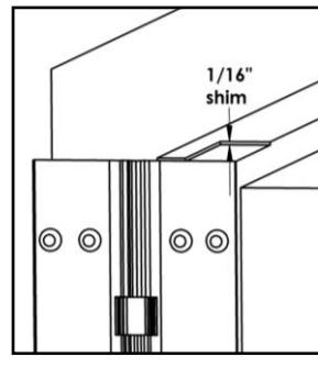
Fig. 1
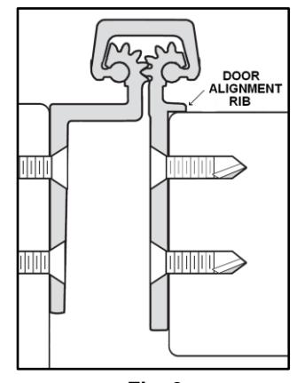
Fig. 2
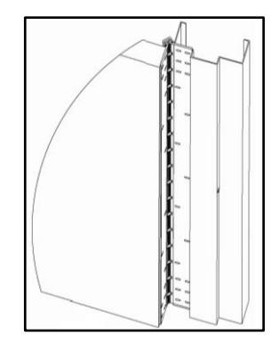
Fig. 3

ROTON INSTRUCTION SHEET PART NO: 75007113 ROTON MODEL: 780-113 REVISION: 05/18/16
HAGER Companies, 139 Victor Street, St. Louis, MO 63104 (800) 325-9995
|
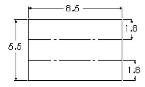
—— 8 . 5 |
||
|---|---|---|
| , • | MACHINE MICHIEF | name. |
| 1.8 | 7.7EV |