Roton 780-111LL Specifications
Open the original PDF document
View PDF

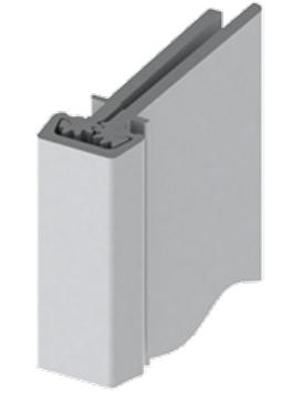
780-111LL
Lead Lined Concealed Leaf Hinge
Application:
- Lead lined model for hospital x-ray room doors with double row of screws to straddle lead (specify "LL")
- Frame and door leaf alignment ribs for proper hinge and door location
- 1/8" (3 mm) inset


PRODUCT SPECIFICATIONS
CLEARANCE:
- 5/16" (8 mm) hinge side
- Plus standard lockside clearance
- Refer to Door and Frame Dimensioning in the General Information section for further details
FASTENERS:
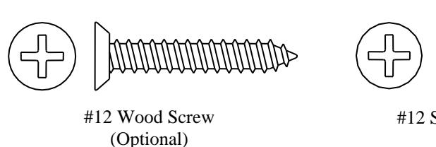
- #12-24 X 11/16" Flat Head Self-Drill Screws
LENGTH OPTIONS:
- Standard and Custom
DOOR REINFORCEMENT:
- None required to 200 lbs. Heavier weight use 16-gauge channel.
FRAME REINFORCEMENT:
- None required to 200 lbs. Heavier weight use 16-gauge channel.
FIRE RATING:
- Up to 3 hr. metal and 90 min. wood composite (with studs)
WARRANTY:
- All Roton products have a lifetime warranty. When ordering electric Roton, the electric portion of the hinge has a one-year warranty.
MATERIAL:
- Aluminum 6063-T6
ELECTRIC
- MODIFICATIONS: - Power Transfer Preparation (EPT 2) or (EPT 10)
- Exposed Electric Contacts (E)
- Exposed Electric Switches (E1S)
- Electric Through-Wire (ETW)
- Electric Monitoring (EMN)
- Electric Through-Wire and Monitoring (ETM)
OPTIONS:
- Hospital Tip
EPD:
- Roton Continuous Hinges Environmental Product Declaration
PRODUCT SIZE OPTIONS
| LENGTH (INCHES) | LENGTH (MM) | HOLE COUNT (DOOR) | HOLE COUNT (JAMB) |
|---|---|---|---|
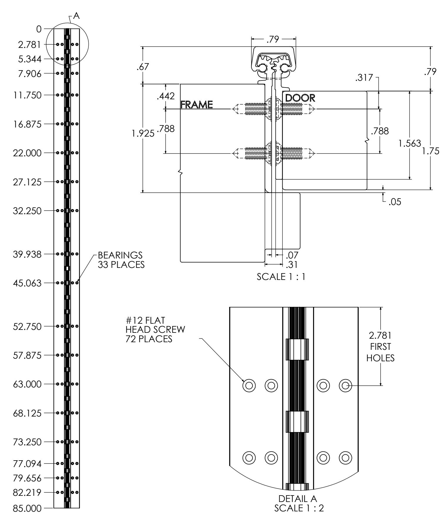
| 79 | 2007 | 32 | 32 |
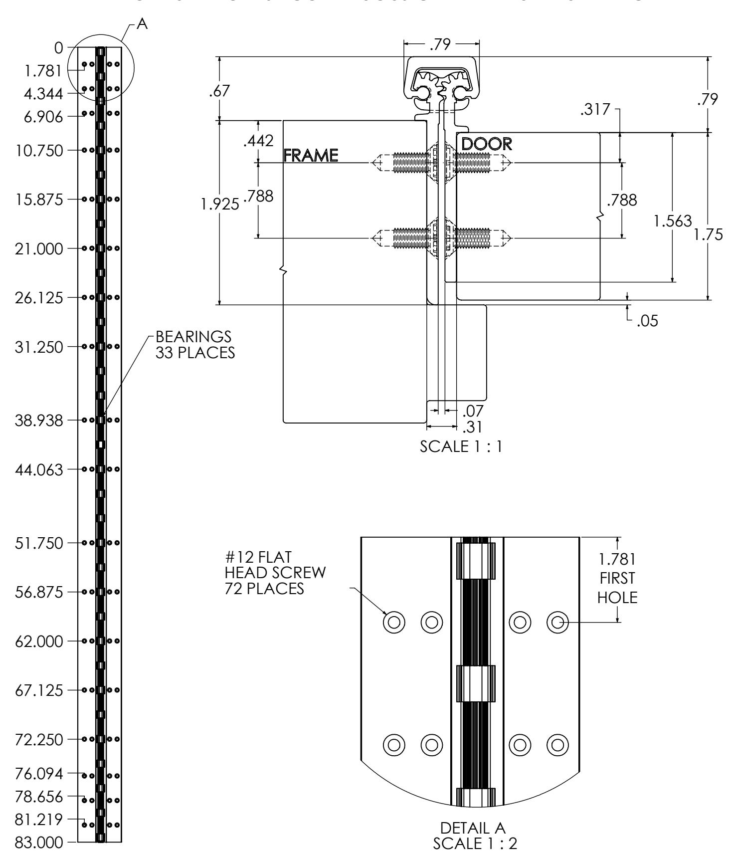
| 83 | 2108 | 36 | 36 |
| 85 | 2159 | 36 | 36 |
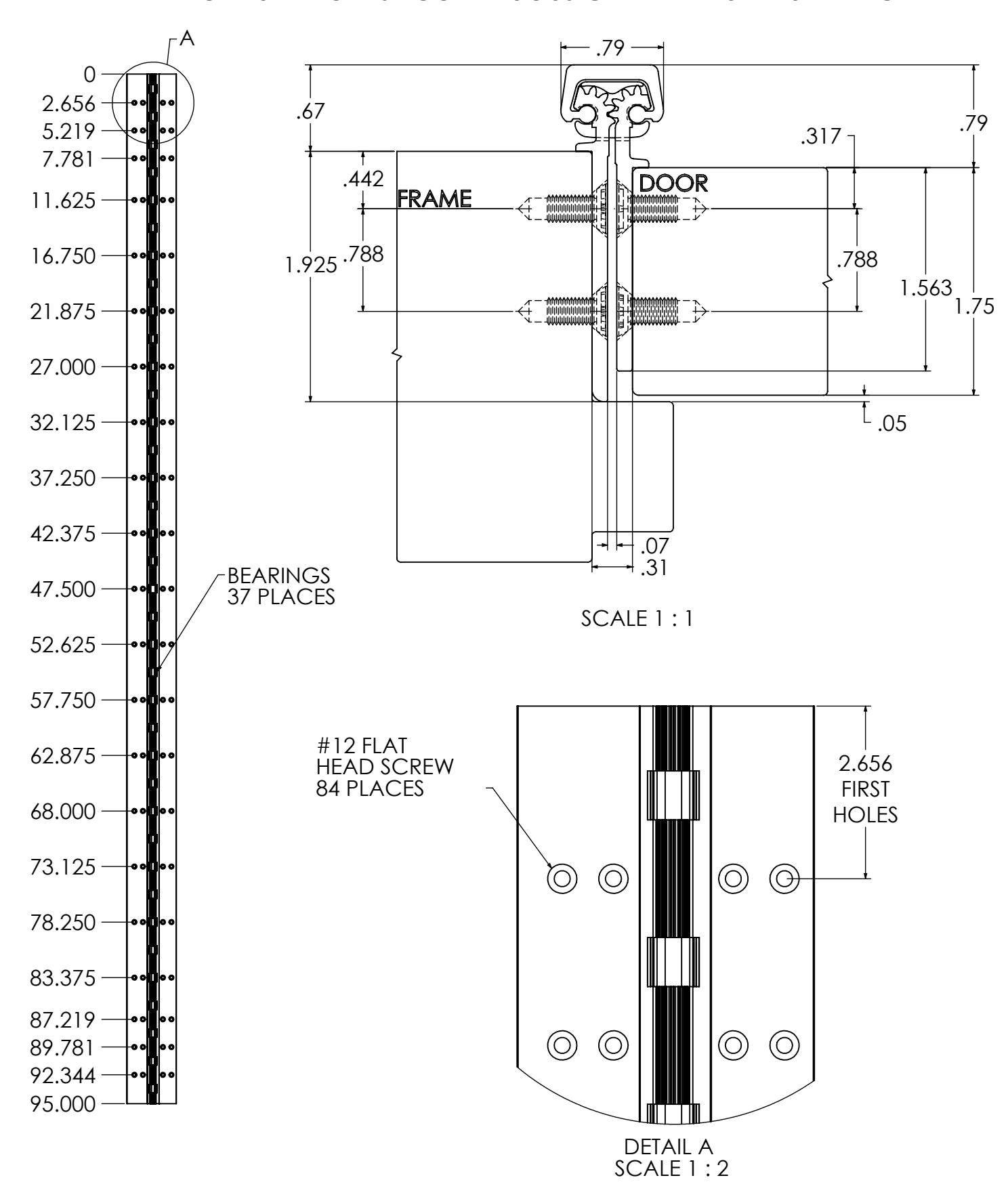
| 95 | 2413 | 42 | 42 |
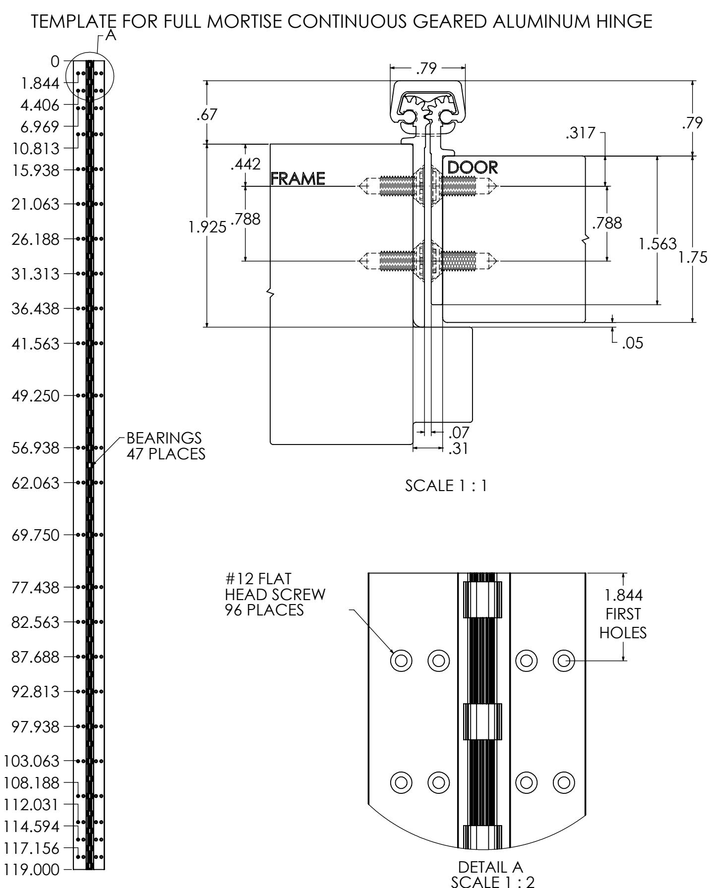
| 119 | 3023 | 48 | 48 |


TEMPLATE FOR FULL MORTISE CONTINUOUS GEARED ALUMINUM HINGE
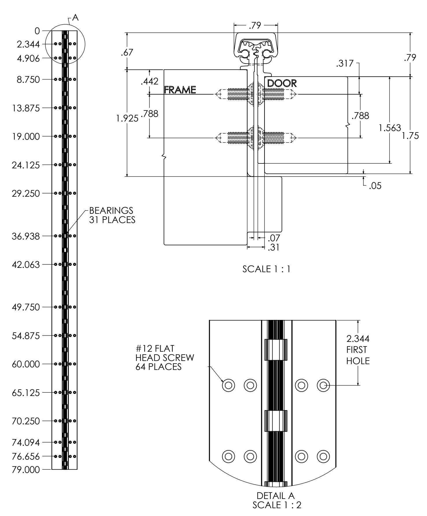
REVISION: 04/22/16

REVISION: 04/22/16
TEMPLATE FOR FULL MORTISE CONTINUOUS GEARED ALUMINUM HINGE

TEMPLATE FOR FULL MORTISE CONTINUOUS GEARED ALUMINUM HINGE
REVISION: 04/22/16


REVISION: 04/22/16
TEMPLATE FOR FULL MORTISE CONTINUOUS GEARED ALUMINUM HINGE
REVISION: 04/22/16

HAGER Companies, 139 Victor Street, St. Louis, MO 63104 (800) 325-9995
ROTON INSTRUCTION SHEET PART NO: 75007112 ROTON MODEL: 780-111, 780-112, 780-226, 780-235 REVISION: 05/16/16
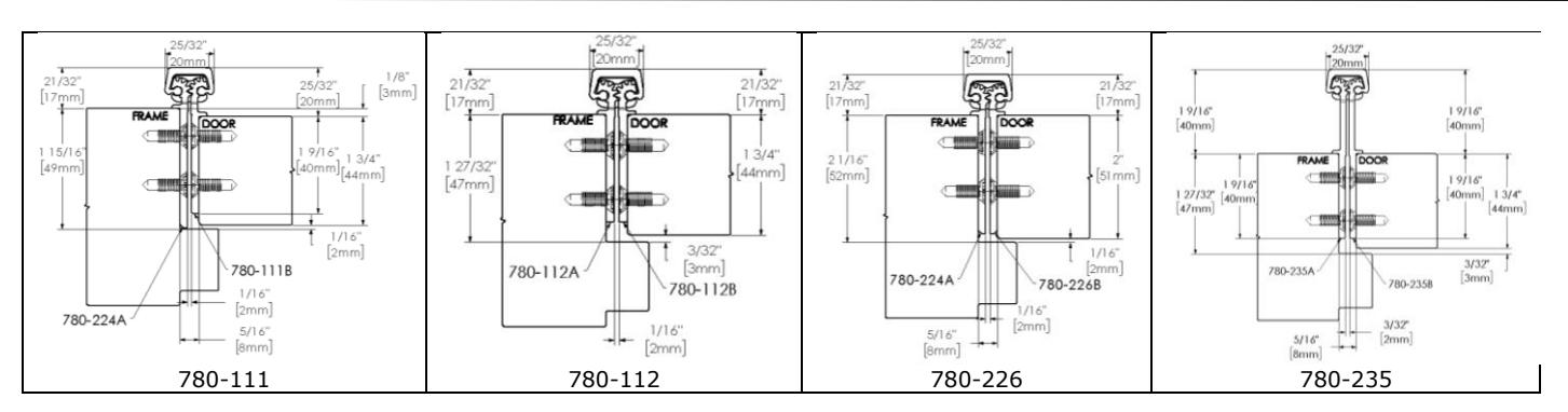
ROTON Models 780-111, 780-112, 780-226 and 780-235 are Aluminum Continuous Geared Concealed Leaf Hinges. Model 780- 111 provides a 1/8" door inset. The others accommodate flush doors. Each can be used with any standard frame without hinge preps, and either with or without reinforcements depending on door weight. Clearance required between the hinge edge of the door and the frame rabbet is 5/16" (7.9mm) minimum. For 780-235 allow for an additional 1/32" to lock side clearance. "HD" models have additional bearings for heavy-duty application. The 780-226 is intended for doors 2" or thicker.
Hinge Length
All ROTON Hinges are supplied approximately 1" shorter than the nominal door height to avoid threshold or carpet clearance problems. If the hinge must be trimmed shorter, first determine the correct hand of the door and orientation of the hinge. Then mark and trim from the bottom of the hinge only – do not cut from the top end.
| NOM. | NOM. HINGE | NUMBER OF | |
| DOOR | LENGTH | FASTENERS | |
| HEIGHT | (FRAME / | ||
| DOOR | |||
| 6' 8" | 79" (2006mm) | 15 / 15 | |
| 7' 0" | 83" (2108mm) | 19 / 19 | |
| 7' 2" | 85" (2159mm) | 19 / 19 | |
| 8' 0" | 95" (2413mm) | 20 / 20 | |
| 10' 0" | 119" (3022mm) | 23 / 23 | |
Total Clearance Between Door And Frame Width
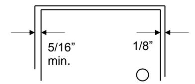
| SINGLE DOOR - SQUARE EDGED | |||||
|---|---|---|---|---|---|
| Hinge thickness | 5/16" (7.9mm) | ||||
| Allowance for frame irregularities | 1/32" (0.8mm) | ||||
| Latch side clearance (typical) |
1/8"
(3.2mm) |
||||
| TOTAL* | 15/32" (11.9mm) | ||||
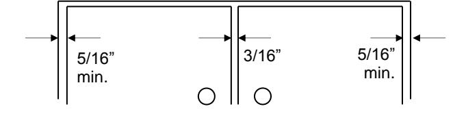
PAIR OF DOORS - SQUARE EDGED
| First hinge thickness | 5/16" (7.9mm) |
| First allowance for frame irregularities | 1/32" (0.8mm) |
| Clearance between doors (typical) | 3/16" (4.8mm) |
| Second hinge thickness | 5/16" (7.9mm) |
| Second allowance for frame irregularities | 1/32" (0.8mm) |
| TOTAL* | 7/8" (22.2mm) |
* For doors that are pre-beveled 1/8"-in-2" on the hinge edge, add 1/32" (0.8mm) per door to the TOTAL clearance shown. (780-235 hinges are not recommended for beveled doors) For 780-235 allow for an additional 1/32" to lock side clearance.
General Fitting Procedure
- For new construction with metal doors/frames: To accommodate the 5/16" (7.9mm) hinge clearance required for these ROTON models, order the door undersized or the frame header oversized. See the clearance information above to attain the proper size. Mortar guards, either Styrofoam or wood, are recommended for frames to prevent grout from interfering with the installation of the hinge fasteners.
- For new site-hung wood doors: If necessary, scribe and cut from the latch edge of the door to leave sufficient hinge stile thickness for proper fastening. A minimum clearance of 5/16" (7.9mm) is required between the hinge edge of the door and the frame rabbet. See the clearance information above to attain the proper finished width of the door.
- For remodeling with existing wood or laminate doors: If necessary, scribe and cut from the hinge edge of the door and plane smooth. A minimum clearance of 5/16" (7.9mm) is required between the hinge edge of the door and the frame rabbet. See the clearance information above to attain the proper finished width of the door.

ROTON INSTRUCTION SHEET
ROTON MODEL: 780-111, 780-112, 780-226, 780-235 HAGER Companies, 139 Victor Street, St. Louis, MO 63104 (800) 325-9995
PART NO: 75007112 REVISION: 05/16/16
Installation Procedure
Frame Preparation
- With the hinge open, place the hinge frame leaf against the frame rabbet making certain that the alignment rib is flush against the frame face along its entire length. Position the top of the hinge 1/16" (1/8" maximum) below the header. Note: A 1/16" shim is recommended due to initial settling of the bearings. (See Fig. 1)
- 2. Mark and center punch the screw hole locations. Accurate location is important for proper installation.
- 3. For metal frames 12 gage or less (≤ .110"/2.8mm), it is not necessary to pre-drill pilot holes if using the self-drilling screws provided. For metal frames thicker than 12 gage (> .110"/2.8mm), drill and tap all mounting holes for #12-24 threads prior to installing the screws. For wood frames, pre-drill pilot holes using a #18 (.170"/4.3mm) bit for optional #12 wood screws.
- 4. Do not attach the hinge to the frame at this time.
Door Preparation
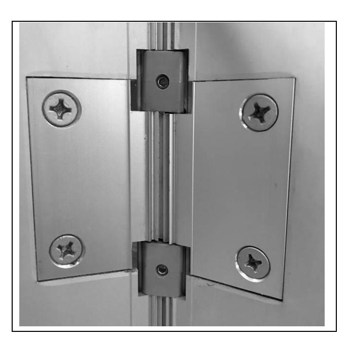
- 1. With the hinge open, place the hinge door leaf against the edge of the door making certain that the door alignment rib is flush against the door face along its entire length (See Fig. 2). Position the top of the hinge flush with the top of the door.
- 2. Mark and center punch the screw hole locations. Accurate location is important for proper installation.
- 3. For hollow metal doors 12 gage or less (≤ .110"/2.8mm), it is not necessary to pre-drill pilot holes if using the self-drilling screws provided. For metal doors thicker than 12 gage (> .110"/2.8mm), drill and tap all mounting holes for #12-24 threads prior to installing the screws. For wood doors, pre-drill pilot holes using a #18 (.170"/4.3mm) bit for optional #12 wood screws (provided with LL models).
- Attach the hinge to the door. For metal doors, use the #12 self-drilling screws provided (recommended driver speed 1,900-2,500 RPM). For wood doors, use optional #12 wood screws.
Hanging the Door
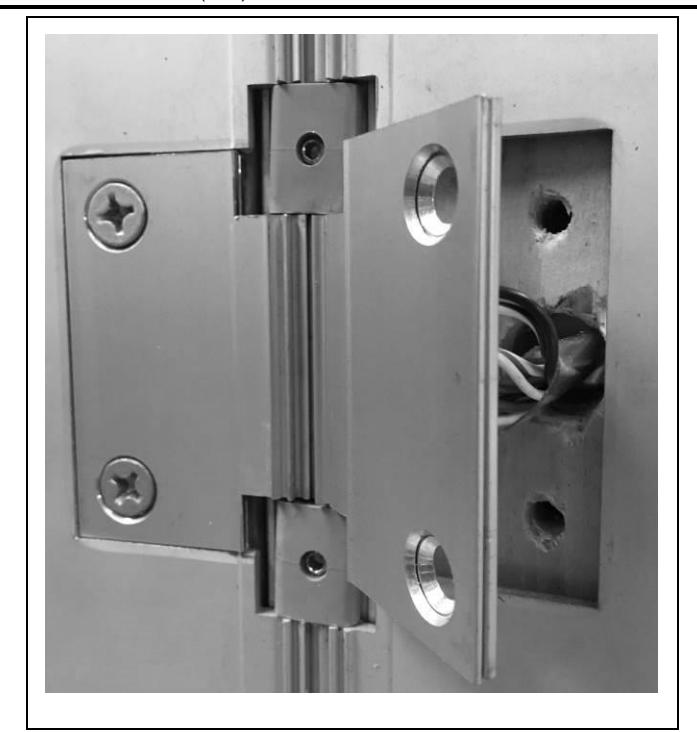
- Position the door (with hinge attached) at 90° to the frame. Attach the hinge to the frame rabbet (See Fig. 3). For metal frames, use the #12 self-drilling screws provided (recommended driver speed 1,900-2,500 RPM). For wood frames, use optional #12 wood screws.
- 2. Make a gentle trial swing. Carefully check the door for proper swing and clearance.
Adjusting the Door
-
If lateral adjustment of the door is required due to excessive or uneven door/frame clearance, adjust by shimming where needed:
- For minor adjustments, an effective shimming material is 1-1/2" cloth duct tape. Apply the tape in stepped layers underneath the frame leaf where needed to build up to the desired thickness.
- b) To shift the entire door, a thin continuous aluminum strip may be used underneath the frame leaf (available in 1/16" (1.6mm) and 1/8" (3.2mm) thicknesses from HAGER).
- Retighten all screws. Carefully check the door for proper swing and clearance.
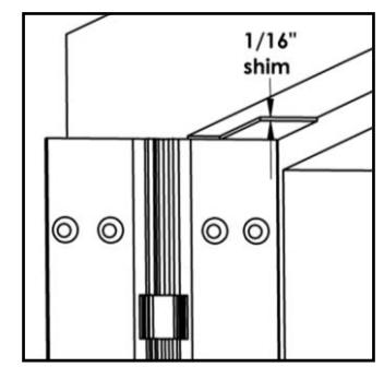
Fig. 1
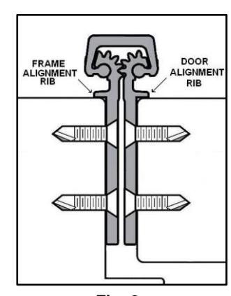
Fig. 2
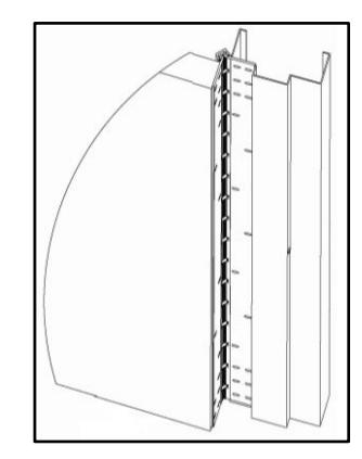
Fig. 3

ROTON INSTRUCTION SHEET PART NO: 75007112
ROTON MODEL: 780-111, 780-112, 780-226, 780-235 REVISION: 05/16/16 HAGER Companies, 139 Victor Street, St. Louis, MO 63104 (800) 325-9995
|
—— 8 . 5 |
||
|---|---|---|
| , • | MACHINE MICHIEF | name. |
| 1.8 | 7.7EV |

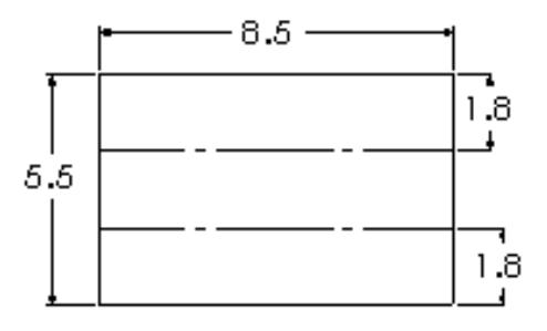
ROTON UL FIRE–RATED STUDS PART NO: 75006111
ROTON MODEL: 780-111, -112, -124, -224, -226, -235 REVISION: 05/31/17 HAGER Companies, 139 Victor Street, St. Louis, MO 63104 (800) 325-9995
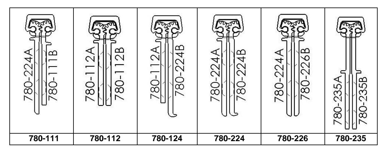
ROTON Hinge U.L. Fire-Rated Studs – 780-111, -112, -124, -224, - 226, -235
These instructions outline how to install the optional stainless steel studs (4) for ROTON Hinge models 780- 112, 780-124 and 780-224. All four studs must be used in order to comply with U.L. requirements for composite wood fire doors rated up to 90 minutes and metal fire doors rated up to 3 hours.
Materials Needed
- Stainless steel studs (4).
- Drill, 3/4" diameter bit, #16 (.177") bit, 12-24 thread tap.
- #10 spanner screwdriver.
| Vertical Location | 79" | 83" | 85" | 95" | 119" |
|---|---|---|---|---|---|
| Hole #1 | 13-7/8" | 15-7/8" | 16-7/8" | 16-3/4" | 13-3/8" |
| Hole #2 | 10-1/4" | 10-1/4" | 10-1/4" | 20-1/2" | 30-3/4" |
| Hole #3 | 30-3/4" | 30-3/4" | 30-3/4" | 20-1/2" | 30-3/4" |
| Hole #4 | 10-1/4" | 10-1/4" | 10-1/4" | 20-1/2" | 30-3/4" |
Installation
- 1. Install the hinge in accordance with the standard installation instructions furnished with the hinge.
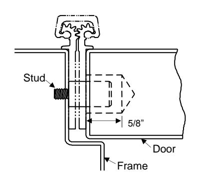
- 2. At the center of each 3/4" diameter pre-drilled hole in the frame leaf , drill and tap a #12-24 threaded hole into the frame (four places).
- 3. At each 3/4" diameter pre-drilled hole in the door leaf , drill a 3/4" diameter x 5/8" deep hole into the edge of the door (four places).
- 4. Insert a stud into each of the four #12-24 threaded holes of the frame and tighten securely using a #10 spanner screwdriver.
- 5. Close the door slowly to assure that the studs are properly aligned. Any minor interference can be corrected using a rat-tail file.

ROTON INSTRUCTION SHEETPART NO: 75009010 Removable Electric for Concealed hinges – RETW Rev: 01.18.19
HAGER Companies, 139 Victor Street, St. Louis, MO 63104 (800) 325-9995
REMOVABLE ELECTRIC THROUGH WIRE
Door and Frame Preparation
- 1. For grout filled frame, install a Mortar Box (HAGER 430). Failure to do so will void the hinge warranty.
- 2. Prepare the door and frame for installation using the standard installation instruction sheet furnished with the hinge.
Installation
- 1. Attach the hinge to the door and frame using the standard installation instruction sheet furnished with the hinge.
- 2. If the door will have a closer on it, disconnect the closer arm. The module is much easier to install with the door fully open.
- 3. Place the marking template into the notched section of the hinge. Make sure it rests flat against the mounting surface and to the outside edge of the hinge.
- 4. Using the transfer punch, center punch both the mounting holes and the wire access hole. See Fig. 1. The middle hole is the wire access hole.
- 5. Repeat steps 2 and 3 for the opposite leaf of the hinge.
- 6. Drill only the 5/8" (3/4" max. for Quick Connect) diameter access hole in both the frame rabbet and the door edge. For metal frames and doors ≤ 0.110" (2.8mm)

Fig. 1
- 7. After drilling, remove any burrs or sharp edges from the holes to prevent damage to the wire leads.
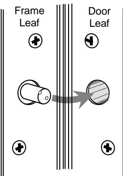
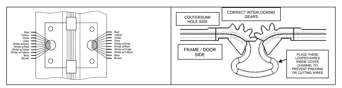
- 8. Identify which leaf gears of the module matches the frame leaf of the installed hinge (the number of gear teeth are different on the frame and door leafs).
- 9. Connect the system wires from the frame to the appropriate leads of the frame leaf side of the module (as described in the system wiring diagram). Insulate the bare end of any unused wires.

screws provided.
ROTON INSTRUCTION SHEETPART NO: 75009010 Removable Electric for Concealed hinges – RETW Rev: 01.18.19
HAGER Companies, 139 Victor Street, St. Louis, MO 63104 (800) 325-9995
- 10. Insert the frame leaf module into the notch of the hinge while carefully pushing the wires back through the access hole in the frame, making sure they are placed so they will not be cut or pinched as the installation is completed. Attach the module to the frame, leaving the screws slightly loose. For metal doors, use the #12 selfdrilling screws provided (recommended driver speed 1,900-2,500 RPM). For wood doors, use the #12 wood
- 11. Connect the system wires from the door to the appropriate leads of the door leaf side of the module. See illustration to the right. Insulate the bare end of any unused wires.
- 12. Insert the door leaf module into the notch of the hinge while carefully pushing the wires back through the access hole in the door, making sure they are placed so they will not be cut or pinched as the installation is completed. Move the door to at least 90 degrees to verify the gears align with the gears in the frame leaf. Make sure the gears you can see are aligned with the other hinge gears above and below. Using the #12 self-drilling screws to attach the module to the door, ensure the proper interlock of gear teeth of the two module components and that the looped wires are placed into the cover channel.
- 13. Tighten all screws in the module, making sure that both leaves of the module are flat and flush with the hinge leaves. A quick visual inspection should show all gears are vertically aligned. Cycle door open and closed to ensure proper alignment with hinge and module.
- 14. Reattach door closer arm if present.
MAXIMUM ELECTRICAL RATING CONTACT THROUGH WIRE
Volts: 48V DC/AC
Amperes: 3.5Amps Continuous

ROTON ELECTRIC MODIFICATION PART NO: 75009017 ROTON MODEL: 780-111, -112, -124, -224, -226 REVISION: 03/20/19
HAGER Companies, 139 Victor Street, St. Louis, MO 63104 (800) 325-9995
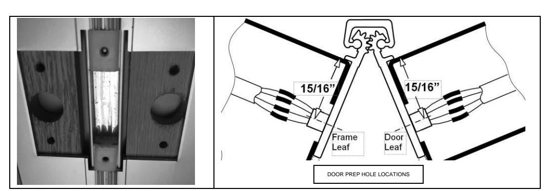
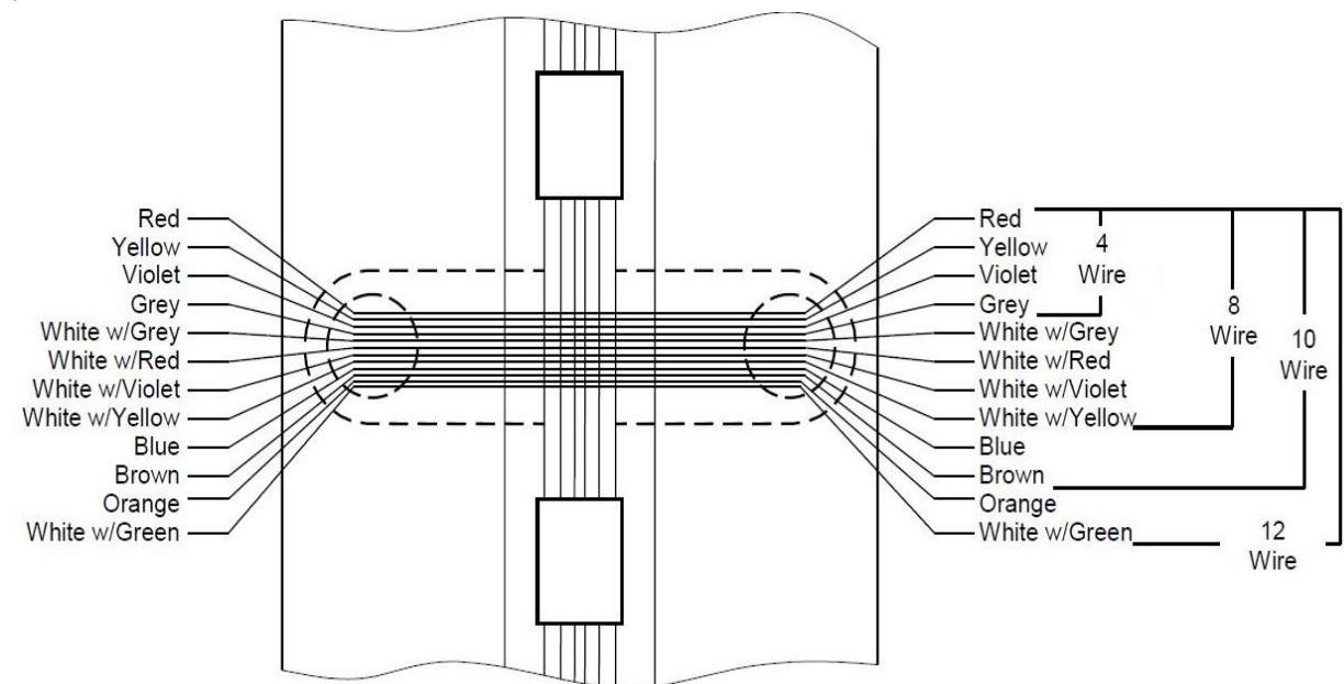
CONCEALED ETW – Electric Through Wires
Door and Frame Preparation
For grout filled frame, install a Mortar Box (HAGER 430). Failure to do so will void the hinge warranty. Refer to Table 2 and Figures below for your particular ROTON Hinge model.
- 1. Drill a 1/2" (5/8" max for Quick Connects) diameter access hole in both the frame rabbet and the door edge for a Concealed Hinge or in the frame and the door face for a Full Surface hinge at the proper location for the wire leads. (12-wire, ETW only, model Concealed Hinges will require two drilled holes in both the frame and door.)
- 2. After drilling, deburr the holes to prevent damage to the wire leads.
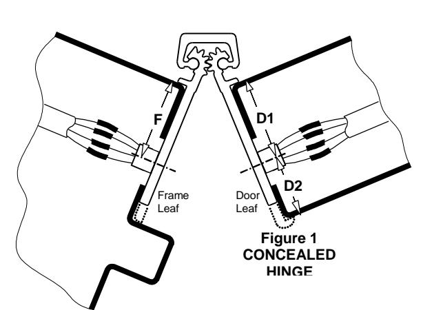
Table 2
|
HINGE
MODEL |
TYPE | F | D1 | D2 |
|---|---|---|---|---|
| 780-111 | Concealed | 15/16" | 13/16" | - |
| 780-112 | Concealed | 15/16" | 15/16" | - |
| 780-124 | Concealed | 15/16" | - | 7/8" |
| 780-224 | Concealed | 15/16" | - | 7/8" |
| 780-226 | Concealed | 15/16" | 15/16" | - |
MAXIMUM ELECTRICAL Figure 2 RATING CONTACT
Volts: 30V dc/ac Amperes: 3.5A Continuous 16A Pulse (300ms)
Recommended: For current ratings greater than 1.0A, use two or more wires in parallel. Make sure same colored wires are connected properly on both sides of hinge.

ROTON ELECTRIC MODIFICATION PART NO: 75009017 HAGER Companies, 139 Victor Street, St. Louis, MO 63104 (800) 325-9995
ROTON MODEL: 780-111, -112, -124, -224, -226 REVISION: 03/20/19
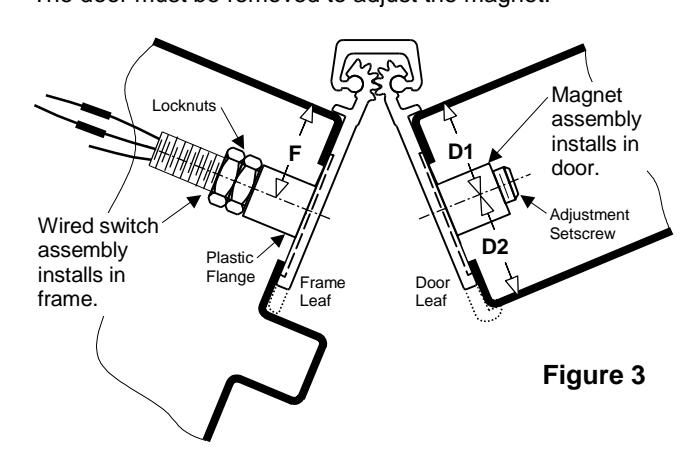
EMN – Concealed Magnetic Switch
Door and Frame Preparation
For grout filled frame, install a Mortar Box (HAGER 430). Failure to do so will void the hinge warranty.
- 1. Prepare the door and frame for installation using the standard installation instruction sheet furnished with the hinge, but do not attach the hinge at this time.
- 2. Locate the wired switch assembly. Peel the adhesive liner from the face of the flange. Attach it in the counter bore on the back of the hinge leaf that will be mounted to the frame . See Figure 3.
-
3. Locate the magnet assembly. The magnet is preset from the factory to activate properly for a metal frame and a metal square-edged door.
- For the following conditions, the magnet assembly must be adjusted using a 5/32" hex key:
- Metal door with a beveled edge on the hinge side turn the adjustment setscrew clockwise 1½ turn.
- Wooden door turn the adjustment setscrew counter-clockwise 1½ turn. Peel the adhesive liner from the face of the flange. Attach the magnet assembly in the counter bore on the back of the hinge leaf that will be mounted to the door . See Figure 3.
-
4. Drill a 3/4" diameter access hole in both the frame rabbet and the door edge at the proper location for the switch and magnet.
- If a shim is utilized in the installation of the hinge, drill a corresponding 3/4" diameter access hole in the shim also. If there is a gap in the shim where the switch or magnet is located, the gap must be no greater than 3/4" so as to provide support for the plastic flange.
- 5. After drilling, deburr the holes to prevent damage to the wire leads.
Installation
- 1. Attach the hinge to the door per the standard installation instruction sheet supplied with the hinge.
- 2. Connect the system wiring to the appropriate leads of the switch. See Figure 3. Insulate the bare end of any unused wires.
- 3. Carefully slide the wires back through the access hole making sure they are placed so they will not be cut or pinched as installation is completed. Attach the hinge to the frame per the standard installation instruction sheet supplied with the hinge.
- 4. Certain factors (frame thickness, door thickness, reinforcements, door material) can slightly affect the sensitivity of the reed switch after installation. Check the circuit to make certain the switch is opening and closing as desired. If necessary, turn the adjustment setscrew in or out to overcome these factors (see Door and Frame Preparation, Step 2). The door must be removed to adjust the magnet.
|
HINGE
MODEL |
F | D1 | D2 |
|---|---|---|---|
| 780-111 | 1" | 7/8" | - |
| 780-112 | 7/8" | 7/8" | - |
| 780-124 | 15/16" | - | 7/8" |
| 780-224 | 15/16" | - | 7/8" |
| 780-226 | 1" | 1" | - |
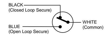
SWITCH INFORMATION Voltage Rating: 200VDC Current Rating: 500mA Switch Function: SPST-NO
CLOSED LOOP SECURE
(Use black and white switch wires.) Closed Loop Secure hinges are wired so that when the door is closed (secured) the EMN switch is closed (passes current). When the door opens, an open circuit is detected as an alarm.
Open Loop Secure
(Use blue and white switch wires.) Open Loop Secure hinges are wired so that when the door is closed (secured) the EMN switch is open (does not pass current). When the door opens, a closed circuit is detected as an alarm.