Roton 780-057 Specifications
Open the original PDF document
View PDF

780-057HD
Heavy Duty Full Surface Hinge
Application:
- Bi-fold applications
- Security moldings


PRODUCT SPECIFICATIONS
CLEARANCE:
- 1/32" (1 mm) minimum recommended for hinge side
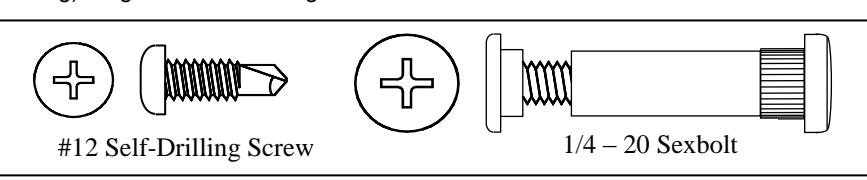
FASTENERS:
- 1/4-20 x 1-1/4" Sexbolt (Screw + Post)
- #12-24 X 11/16" Flat Head Self-Drill Screws
LENGTH OPTIONS:
- Standard and Custom
DOOR REINFORCEMENT:
- None required
FIRE RATING:
- Up to 3 hr. metal and 90 min. wood composite (with studs)
WARRANTY:
- All Roton products have a lifetime warranty. When ordering electric Roton, the electric portion of the hinge has a one-year warranty.
MATERIAL:
- Aluminum 6063-T6
OPTIONS:
- Hospital Tip
EPD:
- Roton Continuous Hinges Environmental Product Declaration
PRODUCT SIZE OPTIONS
| LENGTH (INCHES) | LENGTH (MM) | SEX BOLTS (DOOR) | SCREWS (JAMB) |
|---|---|---|---|
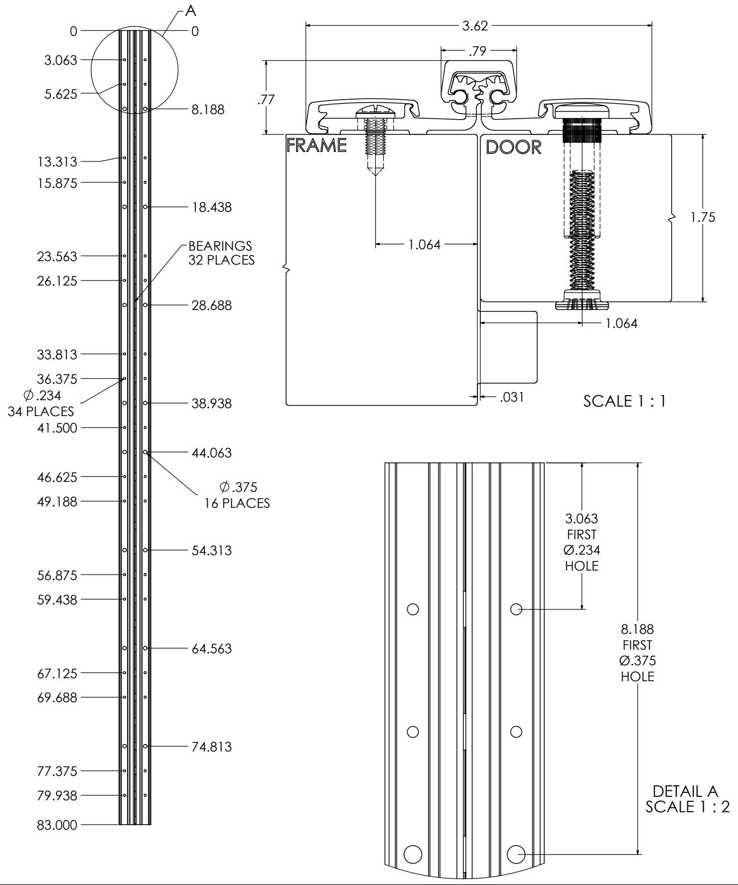
| 79 | 2007 | 16 | 34 |
| 83 | 2108 | 16 | 38 |
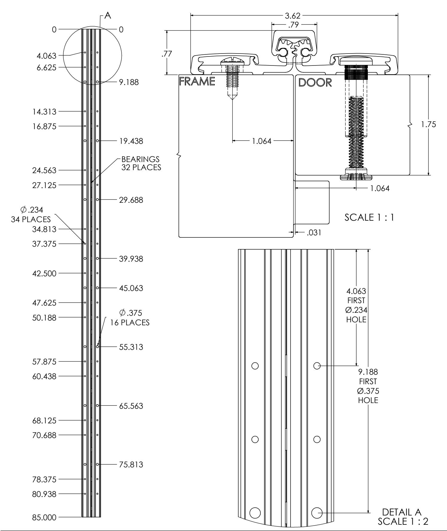
| 85 | 2159 | 16 | 38 |
| 95 | 2413 | 20 | 38 |
| 119 | 3023 | 24 | 46 |

ROTON INSTRUCTION SHEET PART NO: 75007057 ROTON MODEL: 780-057 REVISION: 05/18/16
HAGER Companies, 139 Victor Street, St. Louis, MO 63104 (800) 325-9995
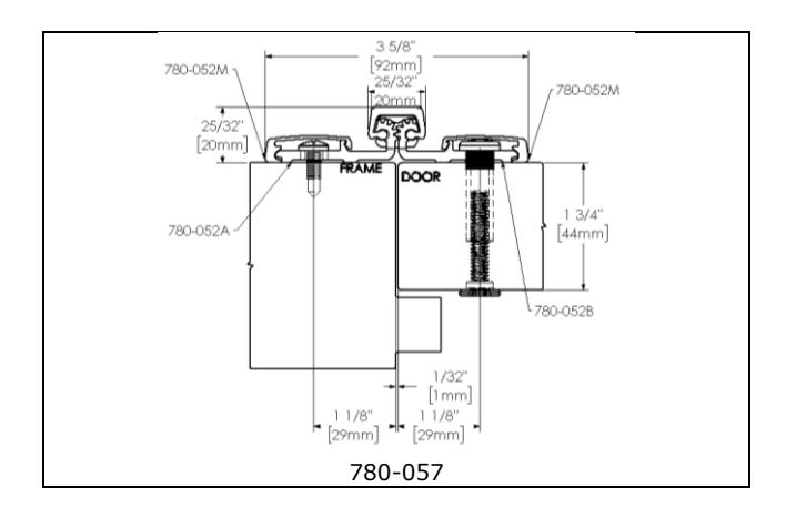
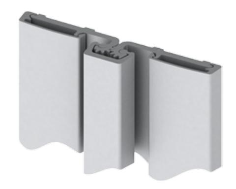
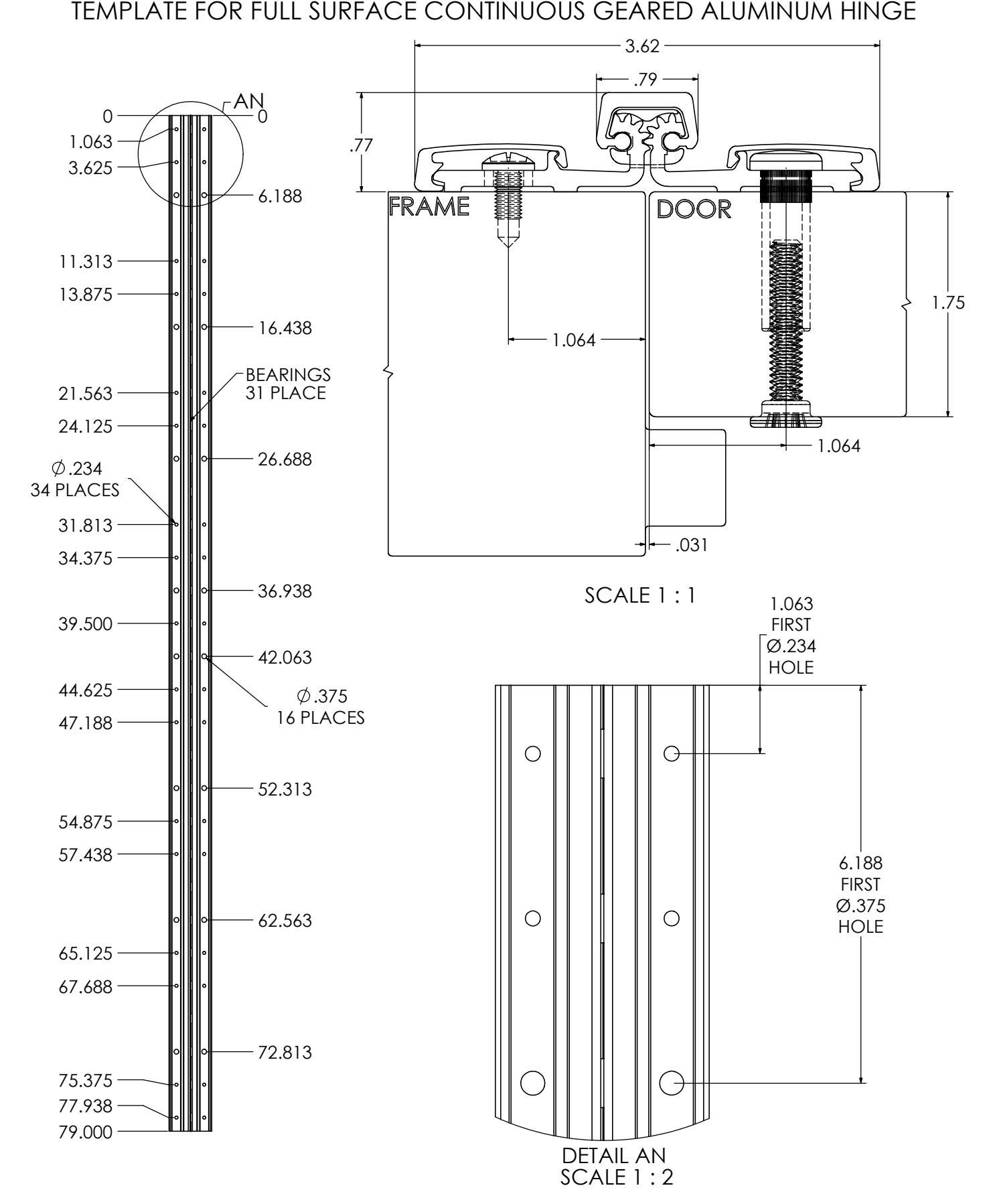
ROTON Model 780-057 is an Aluminum Continuous Geared Full Surface Hinge. It can be used with any standard frame without hinge preps, and either with or without reinforcements depending on door weight. The frame face must have a flat surface at least 1-1/32" wide. Minimum clearance between the hinge edge of the door and the frame rabbet is 1/32" (1mm). "HD" models have additional bearings for heavy-duty application. Doors 1-7/8" to 2-1/4" require optional screws.
Hinge Length
All ROTON Hinges are supplied approximately 1" shorter than the nominal door height to avoid threshold or carpet clearance problems. If the hinge must be trimmed shorter, first determine the correct hand of the door and orientation of the hinge. Then mark and trim from the bottom of the hinge only – do not cut from the top end.
| NOM. | NOM. HINGE | NUMBER OF |
|---|---|---|
| DOOR | LENGTH | FASTENERS |
| HEIGHT | (FRAME / | |
| DOOR | ||
| 6' 8" | 79" (2006mm) | 25 / 25 |
| 7' 0" | 83" (2108mm) | 27 / 27 |
| 7' 2" | 85" (2159mm) | 27 / 27 |
| 8' 0" | 95" (2413mm) | 29 / 29 |
| 10' 0" | 119" (3022mm) | 35 / 35 |
Total Clearance Between Door And Frame Width
SINGLE DOOR Hinge side clearance (typical) 1/8" (3.2mm) Latch side clearance (typical) 1/8" (3.2mm) TOTAL 1/4" (6.4mm)
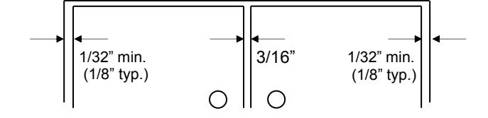
PAIR OF DOORS First hinge side clearance (typical) 1/8" (3.2mm) Clearance between doors (typical) 3/16" (4.8mm) Second hinge side clearance (typical) 1/8" (3.2mm) TOTAL 7/16" (11.2mm)
General Fitting Procedure
- For new construction with metal doors/frames: To accommodate the proper clearance between the door and frame, order the door oversized or the frame header undersized. See the clearance information above to attain the proper size. A minimum clearance of 1/32" (0.8mm) is required between the hinge edge of the door and the frame rabbet. Mortar guards, either Styrofoam or wood, are recommended for frames to prevent grout from interfering with the installation of the hinge fasteners.
- For new site-hung wood doors: If necessary, scribe and cut from the latch edge of the door to leave sufficient hinge stile thickness for proper fastening. See the clearance information above to attain the proper finished width of the door. A minimum clearance of 1/32" (0.8mm) is required between the hinge edge of the door and the frame rabbet.
- For remodeling with existing wood or laminate doors: If necessary, scribe and cut from the hinge edge of the door and plane smooth. See the clearance information above to attain the proper finished width of the door. A minimum clearance of 1/32" (0.8mm) is required between the hinge edge of the door and the frame rabbet.

ROTON INSTRUCTION SHEET PART NO: 75007057 ROTON MODEL: 780-057 REVISION: 05/18/16
HAGER Companies, 139 Victor Street, St. Louis, MO 63104 (800) 325-9995
Installation Procedure
Frame Preparation (See Fig. 1)
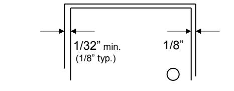
- 1. The frame face must have a flat surface at least 1-1/32" wide to support the hinge. If wider than 1-1/32" mark a line on the frame face 1-1/16" to 2-1/16" from the center of the gap between the door and jamb. For a typical 1/8" hinge side gap, the line will be 1-11/16" from the center of the gap.
- 2. Place the outer edge of the hinge frame leaf on this mark, with the top of the hinge positioned 1/16" (1/8" maximum) below the level of the header rabbet. Note: A 1/16" shim is recommended due to initial settling of the bearings.
- 3. Mark and center punch the screw hole locations. Accurate location is important for proper installation.
- 4. For metal frames 12 gage or less (≤.110"/2.8mm), it is not necessary to pre-drill pilot holes if using the self-drilling screws provided. For metal frames thicker than 12 gage (>.110"/2.8mm), drill and tap all mounting holes for #12-24 threads prior to installing the screws. For wood frames, pre-drill pilot holes using #18 (.170"/4.3mm) bit for optional #12 wood screws. (Optional sexbolt mounting for panel to panel application) - Mark and center punch the locations of the larger 3/8" diameter holes. Rotate the hinge leaf out of the way. At each mark, drill a hole completely through the panel using a 3/8" (9.5mm) bit.
- 5. Attach the hinge to the frame face. For metal frames, use the #12 self-drilling screws provided (recommended driver speed 1,900-2,500 RPM). For wood frames, use optional #12 wood screws
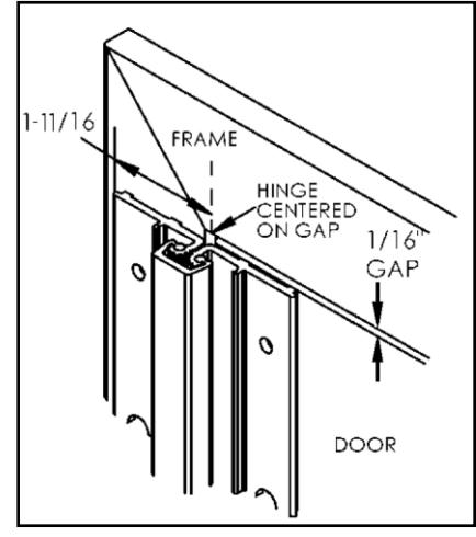
Fig. 1
Door Preparation
- 1. Rotate the hinge door leaf out of the way and set the door into the frame, using shims or wedges to adjust for the desired clearance on all sides.
- 2. Allow an additional 1/32" of clearance on the latch edge of the door at the top only. This will allow for any settling or twisting of the frame that may occur after the shims are removed and the weight of the door is transferred entirely to the frame.
- 3. Allow 1/16" clearance between the top of the door and the frame header rabbet. A good method for this is to use a 1/16" thick shim placed over the top edge of the door.
- 4. With the door held securely in place, rotate the hinge leaf into position on the face of the door.
-
5. (Standard sexbolt mounting) Mark and center punch the locations of the larger 3/8" diameter holes.
Accurate location is important for proper installation.
Rotate the hinge leaf back out of the way. At each mark, drill a hole completely through the door using a 3/8" (9.5mm) bit.
- (Optional mounting without sexbolts) Mark and center punch the locations of the smaller 15/64" diameter holes. For metal doors, use optional #12 self-drilling screws. For wood doors, pre-drill pilot holes using a #18 (.170"/4.5mm) bit for optional #12 wood screws.
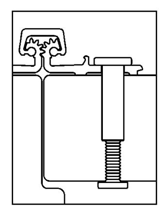
Fig. 2
Hanging the Door (See Fig. 2)
- 1. Attach the hinge to the door as shown. Sexbolts may be reversed if additional security is needed on the push face of the door, but once the molding is in place reversed sexbolts cannot be accessed for maintenance or removal.
- 2. Remove all shims and wedges and make a gentle trial swing. Carefully check the door for proper swing and clearance.
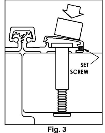
Install the Snap-On Molding (See Fig. 3)
1. For both door and frame leaf – Locate and loosen the retaining setscrew on the edge of the molding with the 5/64" hex key provided. Hook the thicker leg of the molding under the outside edge of the door leaf along the full length of the hinge. Starting at the top and working downward, press or gently tap the opposite leg of the molding in place (if necessary use a rubber mallet or wood block under a hammer, taking care not to damage the molding). Tighten the retaining setscrew.

ROTON INSTRUCTION SHEET PART NO: 75007057 ROTON MODEL: 780-057 REVISION: 05/18/16
HAGER Companies, 139 Victor Street, St. Louis, MO 63104 (800) 325-9995

| 8.5 — | |||||
|---|---|---|---|---|---|
| 1.8 | MACOUT MOISE | name. | |||


REVISION: 04/01/17


REVISION: 04/01/17
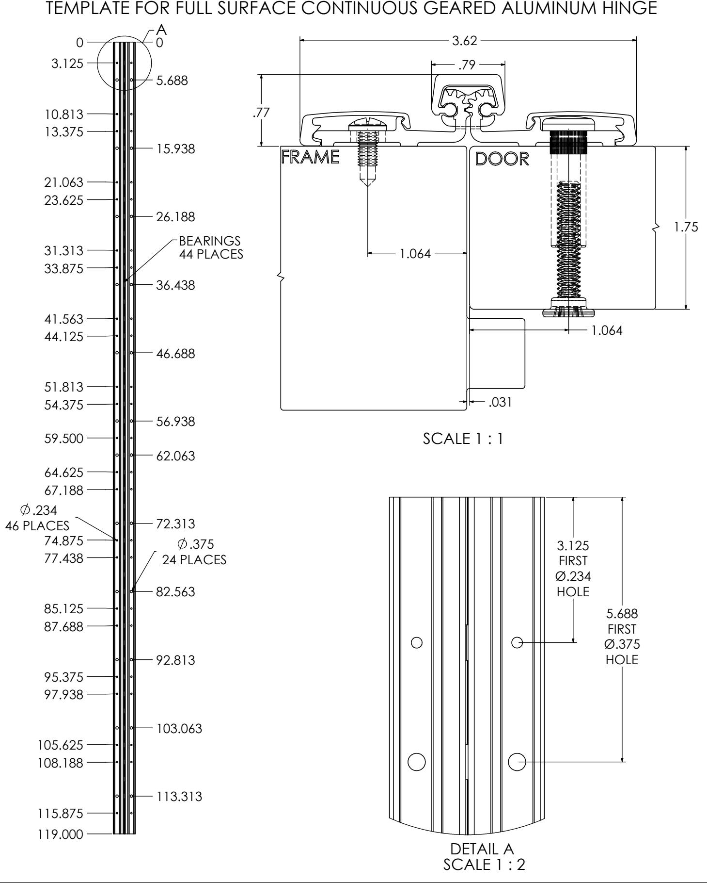
TEMPLATE FOR FULL SURFACE CONTINUOUS GEARED ALUMINUM HINGE


TEMPLATE FOR FULL SURFACE CONTINUOUS GEARED ALUMINUM HINGE
REVISION:
04/01/17


REVISION: 04/01/17
TEMPLATE FOR FULL SURFACE CONTINUOUS GEARED ALUMINUM HINGE
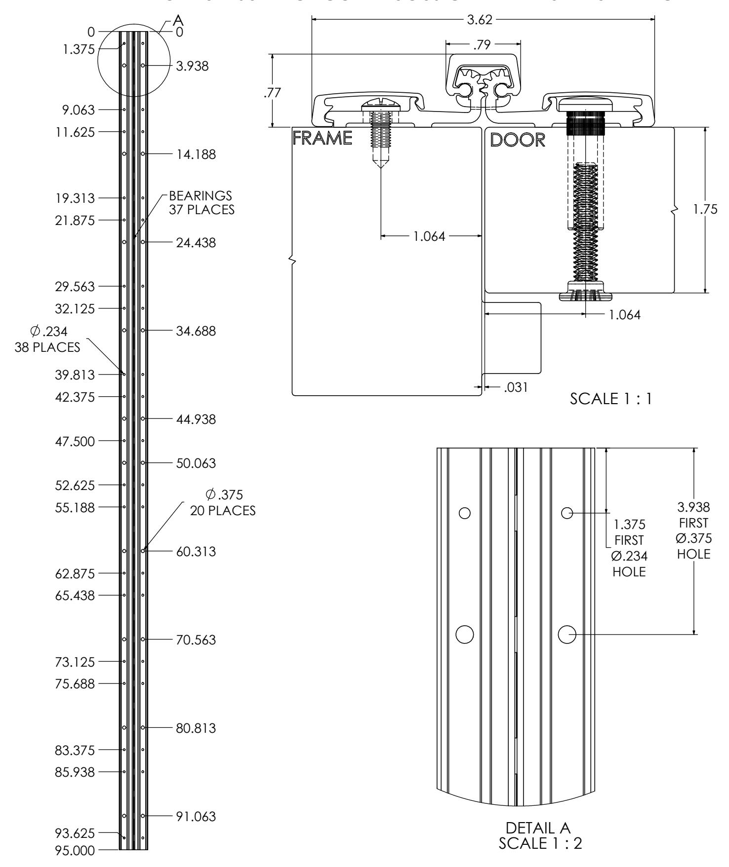

780-057-HD-119
REVISION:
04/01/17