Rockwood OH1000 Series Surface Mounted Door Stops and Holders Templates
Open the original PDF document
View PDFArchitectural Door Accessories
ASSA ABLOY
Rockwood OH1000 Series Surface Mounted Door Stops and Holders
The global leader in door opening solutions
NOT TO SCALE
Template T-OH1000
Effective date: January 1, 2017 Supercedes: All Previous
NOTE: ASSA ABLOY reserves the right to make product changes and is not responsible for obsolete template errors. To ensure your template is current, please visit our website at www.rockwoodmfg.com or call us at 800-458-2424
B—A—C——————————————————————————————————
Jamb: " Flat Head Wood Screws or " Flat Head Machine Screws
Door: #12-24 x 11/2" Flat Head Machine
Screws and 5/16" Ø Sex Bolts
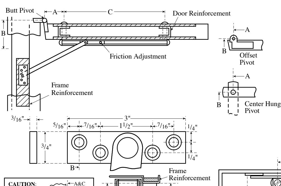
INSTALLATION INSTRUCTIONS
"A" and "B" dimensions.
Note location
of swing clear hinge centerline to determine
- 1. Select proper dimensions from chart on back side of page.
- 2. Locate "A" and "B" dimensions on door and frame.
- 3. Install jamb bracket on stop strip as shown.
- 4. Position channel on door with shock end located towards pivot. Drill " dia. sex bolt hole, "A" dimension, " down from stop strip as shown.
Reinforcement
5. Install channel on door with "A" dimension sex bolt. Locate "C" dimension sex bolt hole making sure that channel is horizontal and parallel with stop strip. Drill 5/16" dia. sex bolt hole and finish installing holder.
NOTES:
• All hollow metal frames should be properly reinforced with <sup>3</sup>/<sub>16</sub>" min. thickness x 12" min. length reinforcement plates.
11/16"
- All hollow metal doors should be properly reinforced.
- All drilling and tapping to be done in field.
- Suggest mounting door stop or holder first and then other hardware to clear. Contact factory if interference results with other hardware.
- Jamb bracket to be on same centerline as channel.
- Intermediate bracket #12 x <sup>3</sup>/<sub>4</sub>" Flat Head Machine Screw.

Page 1 0f 2

Rockwood OH1000 Series Surface Mounted Door Stops and Holders (cont.)
When using center hung pivots, check pivot manufacturer's compatibility prior to specifying.
- 1. See other side for installation instructions.
- 2. Select proper dimensions noted below.
- 3. Add 5/8" to "A" dimension for dead stop.
- 4. All dimensions given in inches.
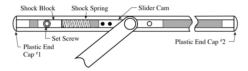
TO SELECT DEGREE OF STOP
- 1. With a 3/16" hex key wrench, loosen the set screw in the shock block.
- 2. Open door to desired degree of opening.
- 3. Slide shock block and spring until the spring touches slider cam.
- 4. Tighten set screw.
- 5. Verify door opening position and re-adjust, as needed.
| Device Number | ||||||
|---|---|---|---|---|---|---|
|
13
/4" - 21 /4" Butts & 3 /4" Offset Pivot |
Stop | Multi | Door Opening | A | B | C |
| 1001S | 1001M | 18 - 24 |
13
/16 |
39
/16 |
1413/16 | |
| 1002S | 1002M |
241
/16 - 30 |
33
/4 |
43
/16 |
16 | |
| 1003S | 1003M |
301
/16 - 36 |
69
/16 |
53
/8 |
173
/4 |
|
| 1004S | 1004M |
361
/16 - 42 |
913/16 |
71
/16 |
203
/16 |
|
| 1005S | 1005M |
421
/16 - 48 |
133
/4 |
85
/16 |
22 |
|
Center
Hung |
Device Number | |||||
|---|---|---|---|---|---|---|
| Stop | Multi | Door Opening | A | B | C | |
| 1001S | 1001M |
21 - 261
/2 |
15
/8 |
4 | 1413/16 | |
| 1002S | 1002M |
269
/16 - 32 |
47
/16 |
47
/8 |
16 | |
| 1003S | 1003M |
321
/16 - 38 |
73
/16 |
6 |
173
/4 |
|
| 1004S | 1004M |
381
/16 - 45 |
103
/8 |
75
/8 |
203
/16 |
|
| 1005S | 1005M |
451
/16 - 48 |
145
/16 |
87
/8 |
22 | |
Page 2 of 2
* Butt mounting only. Reversible, non-handed.