Rixson HM51 Series Floor Closer 3-4 Offset Hinged Single Acting Handed Installation Instructions
Open the original PDF document
View PDFPAGE 4 Closer Adjustment
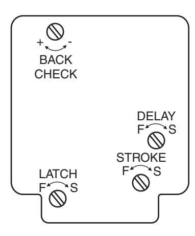
Closing speeds can be adjusted to suit local conditions and requirements. Label on closer face designates the purpose of each adjustment screw. Adjustments are for speed control.
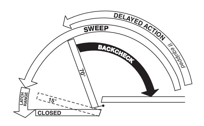
- A. The stroke valve allows adjustment from open to 15°.
- B. The latch valve allows adjustment from 15° to closed
- C. IMPORTANT: Back check valve option must be adjusted to vary resistance from light to firm at 70° of door opening.
- D. The delay valve option allows closing speed adjustment from open position to 65°.
Closer Removal or Reinstallation
Before removing or installing closer, close down valve screws. When reinstalling, lock closer in hold-open position if provided.
Closer Removal:
- 1. Remove thru-bolts, arm cap and loosen arm locking screw.
- 2. Open door to hold-open or (approx.) 90° and close. (If non hold-open is being removed, insert a flat blade (10" min) screwdriver between spindle and torque washer to prevent spindle from turning.)
- 3. Remove arm, shim and torque washer from spindle.
- 4. With door open, remove threshold.
- 5. Remove closer mounting screws (4) and slide closer out under door.
Closer Reinstallation:
Reverse above procedure when reinstalling closer. Before attaching arm, closer spindle must be in hold-open or rotated to 90°. Non hold-open closers will require the use of a flat blade (10" min.) screwdriver For rotating the spindle.
ASSA ABLOY is the global leader in door opening solutions, dedicated to satisfying end-user needs for security, safety and convenience. Rixson® is a registered trademark of Yale Security Inc., an ASSA ABLOY Group company. Copyright© 2005, 2009, Yale Security Inc., an ASSA ABLOY Group company All rights reserved. Reproduction in whole or in part without the express written permission of Yale Security Inc. is prohibited

RIXSON
ASSA ABLOY
Installation Instructions 5100HM (06-09)
HM51 Floor Closer
3/4" Offset Hinged Single Acting Handed
Template

Notes:
- 1. Do not scale drawing.
- 2. All dimensions given in inches.
- 3. Rixson design thresholds available on request.
- 4. Do not remove grind plate until closer is installed. 5. No built-in dead stop. External stop required, by
Right Hand Shown Conversion from inches
to metric: inch x 25.4
Rixson Specialty Door Controls 866-474-9766 Technical Department Rixson Specialty Door Controls www.rixson.com 866-474-9766 Technical Department www.rixson.com
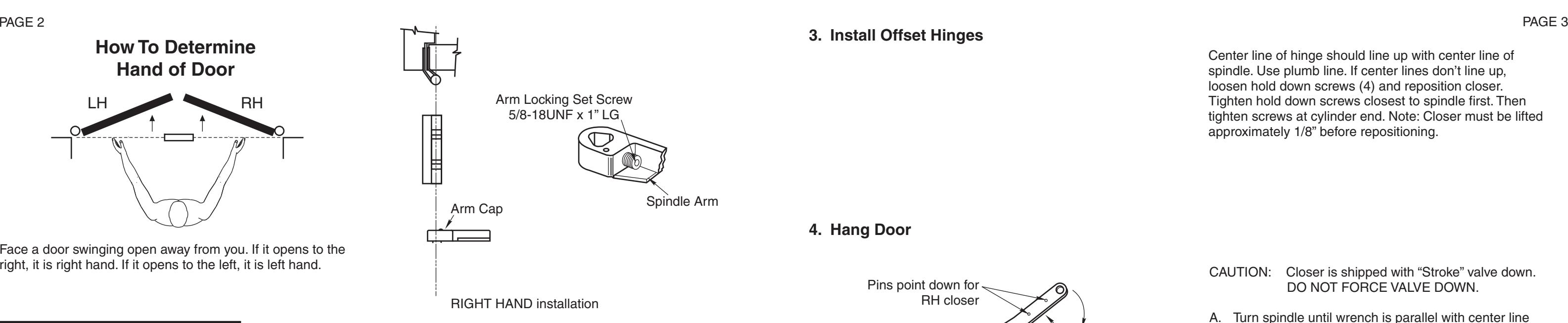
How To Determine Hand of Door
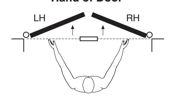
Face a door swinging open away from you. If it opens to the right, it is right hand. If it opens to the left, it is left hand.
Installation Instructions
1. Install Closer
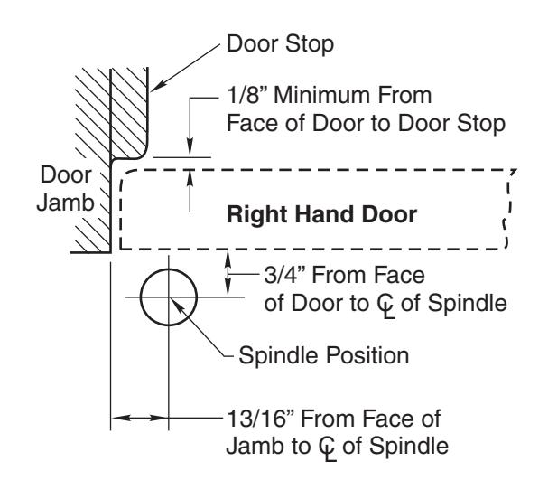
- A. Measure 13/16" out from door jamb.
- B. Allow 1/8" minimum clearance from door stop to door face. Measure door thickness. Add 3/4".
- C. Where lines meet determines center line of closer.
2. Install Cement Case in Floor
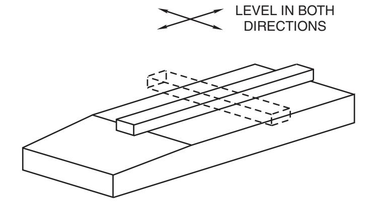
- A. Cement case is set flush with floor.
- B. Set cement case in floor and block in position.
- C. Case should be parallel with center line of door.
- D. CEMENT CASE MUST BE LEVEL. Place levels per illustration.
- E. Grout in cement case with closer. Cement should not get between closer and case.
3. Install Offset Hinges
Center line of hinge should line up with center line of spindle. Use plumb line. If center lines don't line up, loosen hold down screws (4) and reposition closer. Tighten hold down screws closest to spindle first. Then tighten screws at cylinder end. Note: Closer must be lifted approximately 1/8" before repositioning.
4. Hang Door
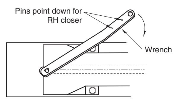
Right Hand Shown
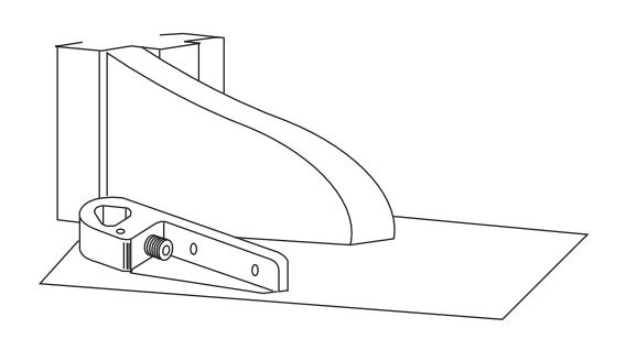
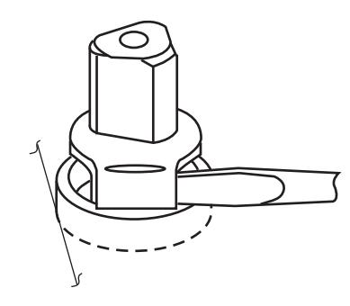
CAUTION: Closer is shipped with "Stroke" valve down. DO NOT FORCE VALVE DOWN.
- A. Turn spindle until wrench is parallel with center line of closer.
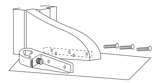
- B. Slip arm on spindle and spot arm mounting holes.
- C. Drill three (3) 3/8" diameter holes in door for arm mounting screws.
- D. Attach arm as shown.
- E. Open Closing Speed and Latch Speed valves (counterclockwise) one turn. Door will then close.