Rixson H40 Series Floor Closer with 587 Arm Center Hung Double Acting H340 Top Pivot Hande Non-Handed Installation Instructions
Open the original PDF document
View PDFCloser Adjustment
Closing speeds can be adjusted to suit local conditions and requirements. Label on closer face designates the purpose of each adjustment screw. Adjustments are for speed control.
Closer Type
This closer is one of three types as follows:
- 1. Non hold-open factory set. No hold-open adjustments.
- 2. Automatic hold-open factory set. No hold-open adjustment.
Spring Power Adjustments
This closer can be adjusted for increased or decreased spring power.
These adjustments if required should be done by an authorized repair agency.
Repairs, parts replacement or internal adjustments must be done by a Rixson authorized repair agency. Consult www.rixsondoorcontrols.com for an authorized repair agency in your area.
ASSA ABLOY RIXSON ®
Rixson® is a registered trademark of Yale Security Inc., an ASSA ABLOY Group company. Copyright© 2006, 2009, Yale Security Inc., an ASSA ABLOY Group company. All rights reserved. Reproduction in whole or in part without the express written permission of Yale Security Inc. is prohibited.
RIXSON ®
PAGE 4
H40 x 587 Arm Floor Closer
Center Hung Double Acting – Handed H340 Top Pivot – Non Handed
Installation Instructions IS4000587 (05-09) Template Notes: 1. Do not scale drawing. 2. Suitable reinforcing by others. 3. Door must have removable panel (by others) for access to arm screws. Removable panel must be on inside of door. 4. Rixson design threshold available on request. 5. Auxiliary stop required. 6. This template is for a 1-3/4" thick door. CL Spindle JAMB PORTION 1/4-20 x 5/8" FHMS or #14 x 1-1/2" FHWS (1 Place) 15/32 1-15/32 6-3/4 21/32 12-24 x 5/8" FHMS or #12 x 1-1/4" FHWS (2 Places) 9/32 9/32 1-5/16 9/32 Maximum Door Clearance DOOR PORTION 5/8 1-1/4 15/32 1/4-20 x 5/8" FHMS or #14 x 1-1/2" FHWS (3 Places) 15/32 7-9/32 2 3 17-1/4 Floor Plate 6-1/8 Jamb 2-5/8 R. Max Cement Case 17 2-9/16 4-1/16 1-3/16 Spindle Shoulder Collar 1/8 2-3/4 9/32 1/4 1 Dia. 1-15/32 1-5/16 Dia. Torrington Roller Bearing JH-1110 1-1/8 1-7/16 H340 HEAVY DUTY TOP PIVOT 1/8 Arm Thrust Bearing See Note 3 3/16 Cement Case Floor Plate Door Mortised 2-1/2" Deep for Arm 6-1/16 WITH THRESHOLD Set Cement Case Flush with Finished Floor 3/16 Threshold Door Mortised Deep for Arm "A" 2-1/4 2 1/4 Threshold 1/2 Threshold A 3/8 3/8 3/8 1-3/8 1 1 1 1 1 1 9 1-1/8 1-1/2 11/16 5/16 OUTSIDE INSIDE ARM NON-HANDED 2-1/4 3/8 3/8 3/8 3/8 1-9/16 Dia. Spindle Shoulder Collar Finished Floor 1-1/2 Drill and C"sink for 5/16-18x2-1/4" FHMS or #18x3" FHWS 5/16-18 FHSC (7 Places) (4 Places) ASSA ABLOY
- 7. For wood doors pre-drill arm and top pivot holes to prevent splitting.
- 8. Heavy duty top pivot with 11/16" dia. pin shown engaged.
- 9. All dimensions given in inches. Metric conversion= 25.4 x inch.
Floor Plate 1/2 Threshold 1/4 Threshold 1 13/16 1-1/16
WITH FLOOR PLATE Set Cement Case 1/8" Below Surface of Finished Floor
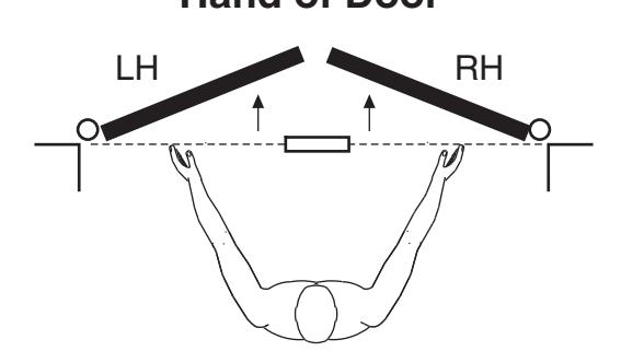
Face a door swinging open away from you. If it opens to the right, it is right hand. If it opens to the left, it is left hand.
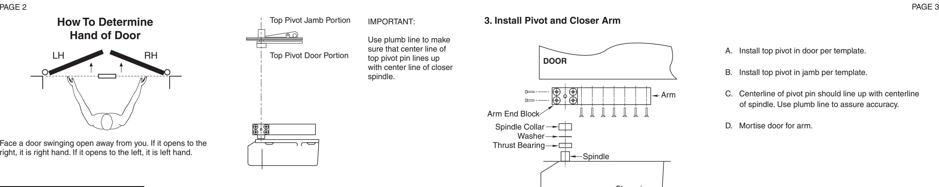
IMPORTANT:
Use plumb line to make sure that center line of top pivot pin lines up with center line of closer spindle.
Installation Instructions
1. Locating Closer
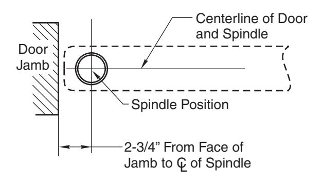
A. Measure 2-3/4" out from door jamb on centerline of door. This is the location of the spindle center.
2. Install Cement Case in Floor
- A. For floor plate application: Cement case is set 1/8" (3.2mm) below floor level.
- B. For threshold application: Cement case is set flush with floor.
- C. Set cement case in floor and block in position.
- D. Case should be parallel with center line of door.
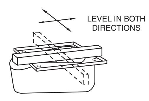
- E. CEMENT CASE SHOULD BE LEVEL. Place levels per Illustration.
- F. Grout in cement case with closer. Cement should not get between closer and case.
3. Install Pivot and Closer Arm
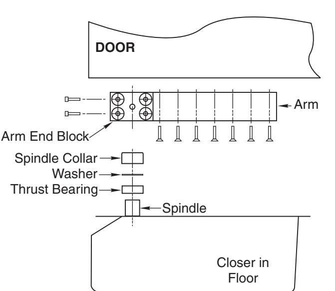
- A. Install top pivot in door per template.
- B. Install top pivot in jamb per template.
- C. Centerline of pivot pin should line up with centerline of spindle. Use plumb line to assure accuracy.
- D. Mortise door for arm.
4. Hang Door
- CAUTION: Closer is shipped with valve screws down. DO NOT FORCE VALVES DOWN.
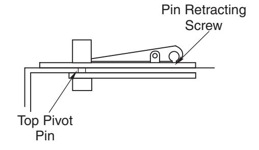
- A. Retract top pivot pin by turning retracting pin screw counterclockwise. (see illustration)
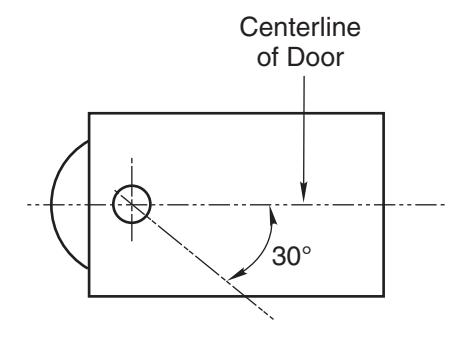
- B. Turn spindle to 30° open position. (see illustration)
- C. Slide door on spindle. DO NOT ATTEMPT TO CLOSE DOOR. Attach arm cap but do not tighten.
- D. Line up two portions of top pivot and turn pin retracting screw clockwise.
- E. Tighten arm end block screws.
- F. Open door to 60° or more and open screw valve by turning screw counterclockwise. Door will then close.