Rixson EH28 Series Floor Closer Center Hung Single Acting H340 Top Pivot Installation Instructions
Open the original PDF document
View PDFCloser Adjustment
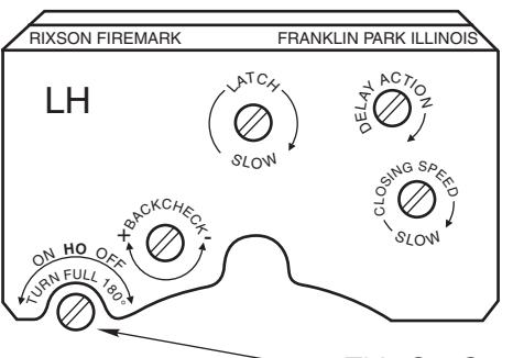
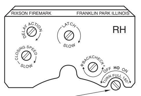
This Set Screw Is On Selector Hold-open Types Only
Closing speeds can be adjusted to suit local conditions and requirements. Label on closer face designates the purpose of each adjustment screw. Adjustments are for speed
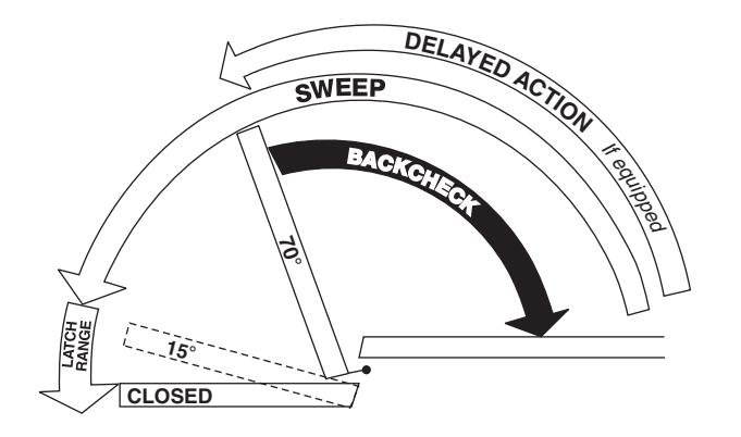
- A. The Delay Action valve allows adjustment from full open to 65° closed position. (Optional)
- B. The Closing Speed valve allows adjustment from full open to 15° on units without the Delay Action feature.
- C. The Closing Speed valve allows adjustment from 65° to 15° closed position on closers with Delay Action feature.
- D. Latch valve allows adjustment from 15° to closed position.
- E. Important: Backcheck adjustment must be adjusted to vary resistance from light to firm at 60° of door open.
Do not use Backcheck as deadstop. This is an intensity valve not speed control.
Closer Type
This closer is one of three types as follows:
- 1. Non hold-open factory set. No hold-open adjustments.
- 2. Automatic hold-open factory set. No hold-open adjustment.
- 3. Selective (on-off) hold-open label will indicate position of on-off selector screw. When turned "on", closer has automatic holdopen: turned "off", hold-open will not function. Turn full 180°.
Spring Power Adjustments
This closer can be adjusted for increased or decreased spring power.
These adjustments if required should be done by an authorized repair agency.
Repairs, parts replacement or internal adjustments must be done by a Rixson authorized repair agency. Consult www.rixson.com for an authorized repair agency in your area.
ASSA ABLOY is the global leader in door opening solutions, dedicated to satisfying end-user needs for security, safety and convenience. Rixson® is a registered trademark of Yale Security Inc., an ASSA ABLOY Group company. Copyright© 2006, 2009, Yale Security Inc., an ASSA ABLOY Group company All rights reserved. Reproduction in whole or in part without the express written permission of Yale Security Inc. is prohibited

RIXSON
PAGE 4
ASSA ABLOY
EH28 x 587 Arm Floor Closer
1-15/32-
Center Hung Single Acting - Handed H340 Top Pivot - Non Handed
1-5/16
12-24NC FHMS x 5/8" or-#12 FHWS x 1-1/4"
21/32
Installation Instructions
ISE2800587 (07-09)
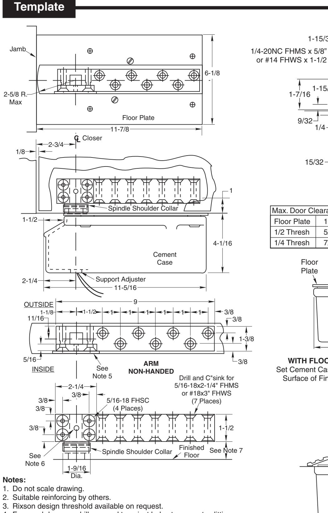
Notes:
- 1. Do not scale drawing
- 4. For wood doors predrill arm and top pivot holes to prevent splitting.
- 5. Door must have removable panel (by others) for access to arm screws. Removable panel must be on inside of door.
- 6. Drill and tap for #8-32 machine screw, centered (screw by others)
- 7. All dimensions given in inches. Conversion from inches to metric: inch x 25.4.
Rixson Specialty Door Controls www.rixson.com
with Finished Floor
866-474-9766 Technical Department
Rixson Specialty Door Controls 866-474-9766 Technical Department www.rixson.com
How To Determine Hand of Door
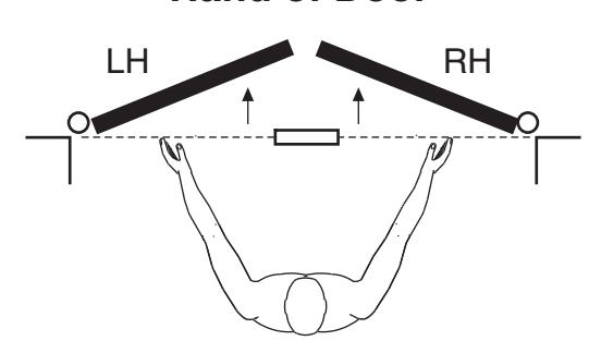
Face a door swinging open away from you. If it opens to the right, it is right hand. If it opens to the left, it is left hand.
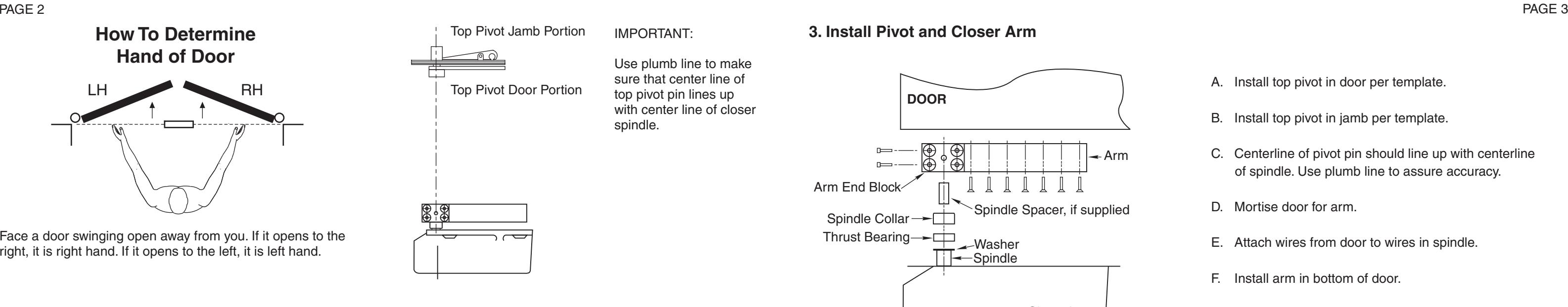
IMPORTANT:
Use plumb line to make sure that center line of top pivot pin lines up with center line of closer spindle.
3. Install Pivot and Closer Arm
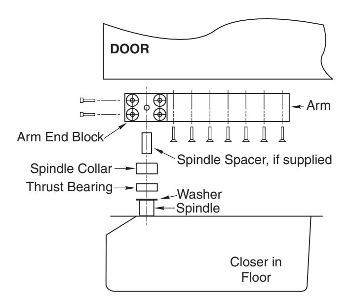
- A. Install top pivot in door per template.
- B. Install top pivot in jamb per template.
- C. Centerline of pivot pin should line up with centerline of spindle. Use plumb line to assure accuracy.
- D. Mortise door for arm.
- E. Attach wires from door to wires in spindle.
- F. Install arm in bottom of door.
Installation Instructions
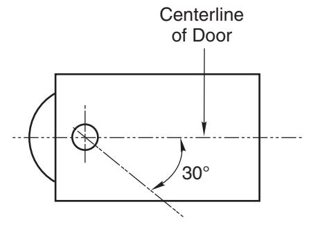
1. Locating Closer
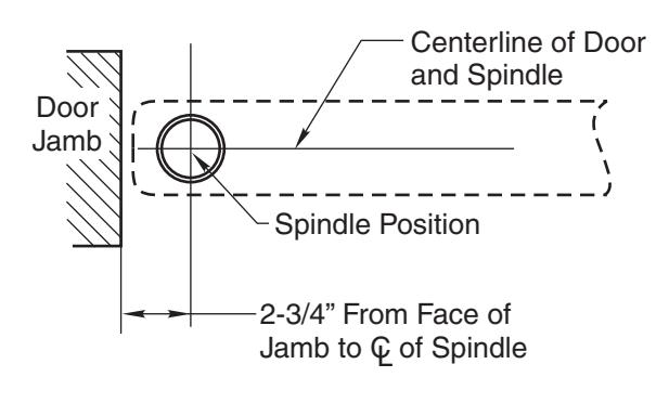
- A. Measure 2-3/4" out from door jamb on centerline of door. This is the location of the spindle center.
- B. Run conduit to closer cutout.
- C. Attach building wires to wires coming out of underside of closer.
4. Hang Door
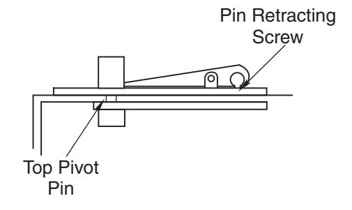
CAUTION: Closer is shipped with valve screws down. DO NOT FORCE VALVES DOWN.
- A. Retract top pivot pin by turning retracting pin screw counterclockwise. (see illustration)
- B. Turn spindle to 30° open position. (see illustration)
- C. Slide door on spindle. DO NOT ATTEMPT TO CLOSE DOOR. Attach arm cap but do not tighten.
- D. Line up two portions of top pivot and turn pin retracting screw clockwise.
- E. Tighten arm end block screws.
- F. Open door to 60° or more and open screw valve by turning screw counterclockwise. Door will then close.
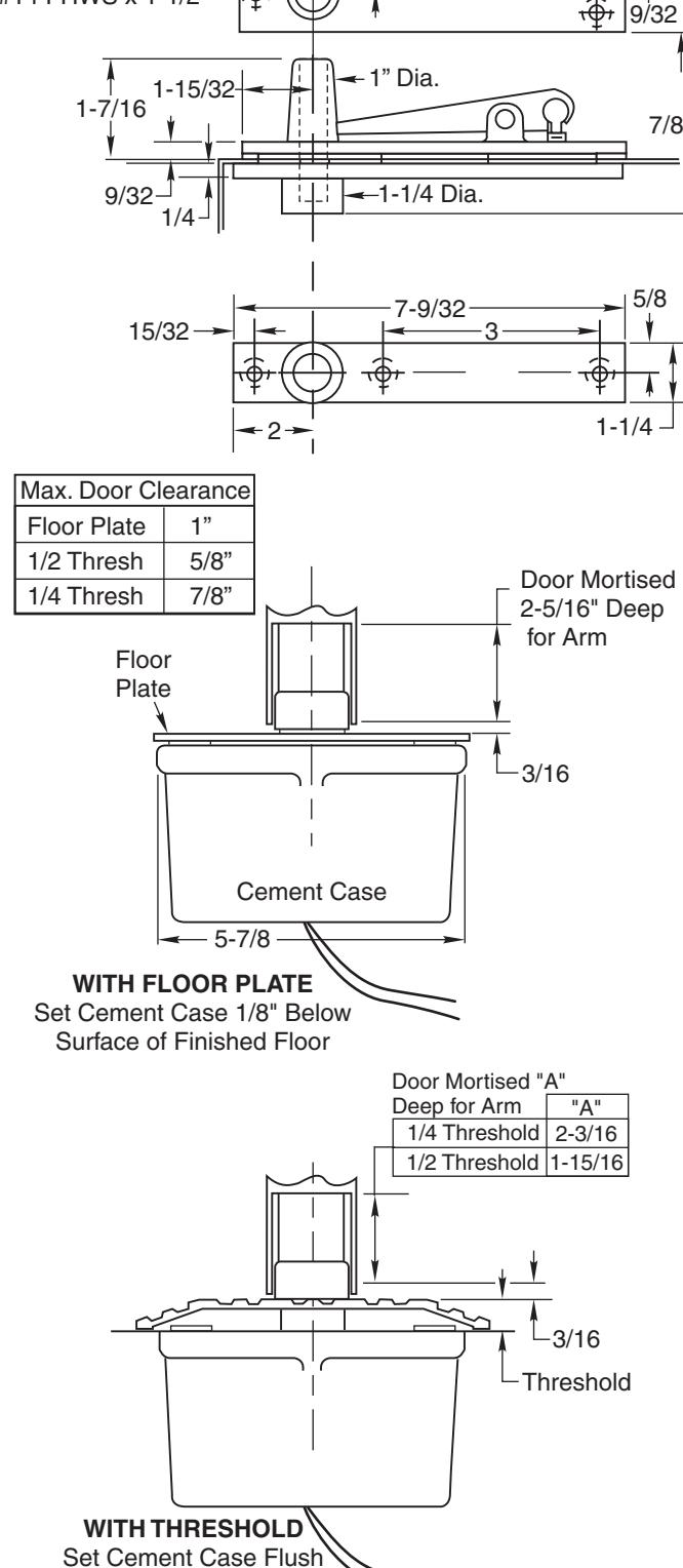
2. Install Cement Case in Floor
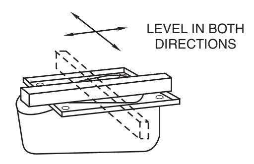
- A. For floor plate application: Cement case is set 1/8" (3.2mm) below floor level.
- B. For threshold application: Cement case is set flush with floor.
- C. Set cement case in floor and block in position.
- D. Case should be parallel with center line of door.
- E. CEMENT CASE SHOULD BE LEVEL. Place levels per Illustration.
- F. Grout in cement case with closer. Cement should not get between closer and case.