Rixson Checkmate No. 2 Series Concealed Door Stop and Holder Inverted Installation Instructions
Open the original PDF document
View PDF
INSTALLATION INSTRUCTIONS
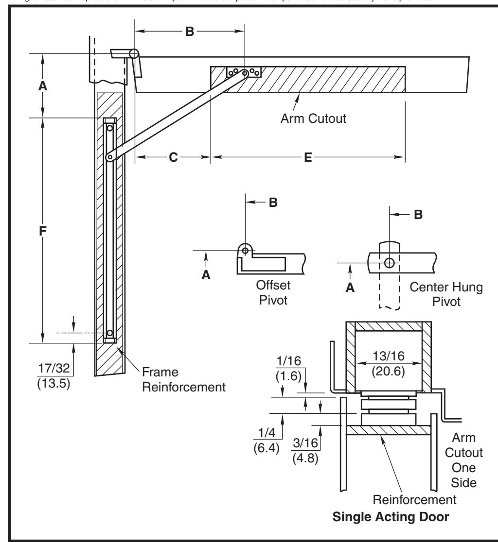
1. Select proper dimensions from chart on opposite side of page.
NOTE: Add 5/8" (15.8) to "A" dimension for dead stop.
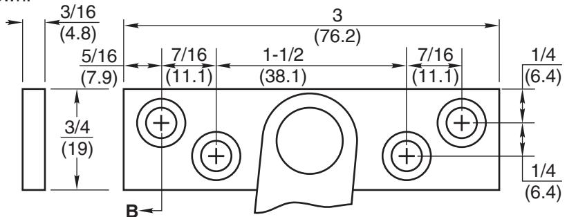
Locate "B" dimension on frame and mortise 7/16" (11) deep for jamb bracket as shown.
- 3. Locate "A" and "F" dimensions on centerline of frame and mortise 13/16" wide x 7/8" deep (20.6 x 22.2) for channel, 1/16" (1.6) head clearance shown. Coordinate the arm and rail cutout dimensions if head clearance varies.
- 4. Locate "C" And "E" dimensions on top of door and mortise 1/4" (6.4) deep as shown for arm clearance.
- 5. Install door stop or holder with screws provided.
Notes:
- All hollow metal frames are to be provided with 3/16" (4.8) min. thickness x 12" (304.8) min. length reinforcement plates.
- All hollow metal doors are to have minimum 3/16" reinforcement plates.
- If dead stop is required add 5/8" (15.8) to "A" dimension as noted on opposite side of page.
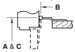
- A, B and C dimensions are measured from centerline of pivot, not edge of door.
- Reversible, non-handed.
- All dimensions are given in inches (mm).
Caution:
Note location of swing clear hinge centerline to determine "A" and "B" dimensions.
| Screw Details | ||||||||
|---|---|---|---|---|---|---|---|---|
| Jamb | Door | |||||||
| #12-24 x 1/2" FHMS | #12-24 x 1-1/2" FHMS | |||||||
| or | or | |||||||
| #12 x 1-1/2" FHWS | #12 x 1-1/2" FHWS | |||||||
No. 2 Series Inverted Concealed Door Stops and Holders
RIXSON ASSA ABLOY
www.rixson.com
TEMPLATE NUMBER
07-16
DATE
OH80010A
No. 2 Series Concealed Door Stops and Holders
Metric = decimal (numerator divided by denominator) x 25.4.
- 1. See other side for installation instructions.
- 2. Select proper dimensions noted below.
- 3. Add 5/8" to "A" dimension for dead stop.
4. All dimensions given in inches.
When Using Center Hung Pivots, Check Pivot Manufacturer's Compatibility Prior to Specifying
* Butt mounting only. Reversible, non-handed.
| Device Number | ||||||||||||
|---|---|---|---|---|---|---|---|---|---|---|---|---|
| 1-3/4 - 2-1/4 | Friction | H.O. | Stop | Multi |
Door
Opening |
A | B | C | E | F | ||
|
(44.5 - 57.2)
Butts |
2-116 | 2-126 | 2-136 | 2-146 | *18 - 24 | 1-3/16 | 3-11/16 | 2-3/4 | 12-13/16 | 15-7/8 | ||
| & | 2-216 | 2-226 | 2-236 | 2-246 | 24-1/16 - 30 | 4 | 4-3/8 | 3-3/4 | 15-1/2 | 17-1/16 | ||
| 3/4 (19) | 2-316 | 2-326 | 2-336 | 2-346 | 30-1/16 - 36 | 6-3/4 | 5-9/16 | 4-3/4 | 18-3/4 | 18-13/16 | ||
| Offset Pivot | 2-416 | 2-426 | 2-436 | 2-446 | 36-1/16 - 42 | 9-7/8 | 7-1/4 | 7 | 23 | 21-1/4 | ||
| 2-516 | 2-526 | 2-536 | 2-546 | 42-1/16 - 48 | 13-13/16 | 8-1/2 | 7-3/4 | 27 | 23-1/16 | |||
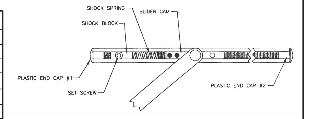
TO SELECT DEGREE OF STOP
- 1. With a 3/16 hex key wrench, loosen the Set Screw in the Shock Block.
- 2. Open door to desired degree of opening.
- 3. Slide Shock Block and Spring until the Spring touches Slider Cam.
- 4. Tighten Set Screw.
- 5. Verify door opening position and re-adjust, as needed.
No. 2 Series Inverted Concealed Door Stops and Holders
ASSA ABLOY RIXSON
www.rixson.com
TEMPLATE NUMBER DATE
®
OH80010B
07-16