Rixson 990M Electromagnetic Door Holder & Release Installation Instructions
Open the original PDF document
View PDF
Notes:
- 1. Do not scale drawing.
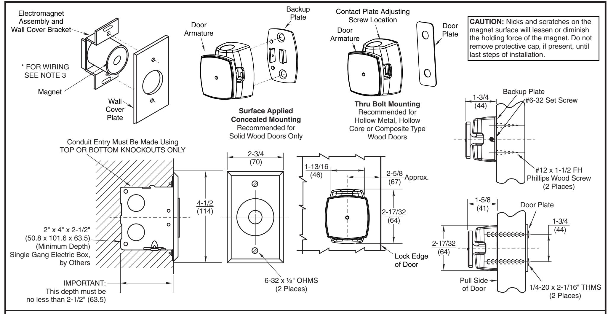
- 2. Total projection 1-7/8" (48mm). (Includes Electromagnet, Armature Assembly and Wall Cover plate.)
- 3. Non-tri voltage magnets have two non-polarized wires to be connected. Tri voltage magnets are connected using a terminal strip on back of magnet. One wire in common and one wire in the appropriate voltage terminal (non-polarized).
- 4. See Step 1 on sheet 2 for Electric Box location. Anchor Electric Box to withstand a
- minimum 50 lb. pull. Electric Box shown installed in vertical position.
- 5. Door closing mechanism should have a 3 lb. closing force at the degree of door opening where door armature and electromagnet engage.
- 6. Door hardware must not project more than 1-5/8" (48mm) on pull side of door.
- 7. Mounting of Electric Box should be reinforced to withstand shock of door opening. Failure to do so will cause box anchors to work loose.
- 8. All dimensions given in inches (mm).
- 9. See sheet 2 for more details.
990M Door Release
ASSA ABLOY RIXSON ®
www.rixson.com
1 of 2
SHEET TEMPLATE NUMBER Rev
DR100215 1
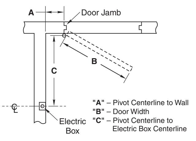
- 1. Use table to locate Single Gang Electric Box.
- 2. Determine door width (Dim "B"). Measure pivot centerline to wall (Dim. "A"). Find dimension "C" in table.
Example: Pivot centerline to wall ("A") = 10" (254mm) Door Width ("B") = 36" (914mm)
Electric Box Centerline ("C") = 33" (838mm)
3. If "A" or "B" falls between the numbers listed in table, allow for difference.
Example: Pivot centerline to wall ("A") = 7" (178mm)
Door Width ("B") = 36" (914mm)
Electric Box Centerline ("C") = 33-5/8" (854mm)
- 4. If dimensions "A" and "B" intersect in shaded area of table DO NOT INSTALL ELECTRIC BOX. The degree of door opening will not permit proper alignment between armature and wall magnet.
- 5. Height to be determined by others. Suggested height is 2' - 4' (610mm - 1219mm) from floor and/or not over 6' (1829mm).
- 6. Check degree of door opening in table and coordinate with door closers and other door hardware.
- 7. Total projection of door hardware must not project more than 1-5/8" (41mm) on pull side of door.
Location of Electric Box
| Door Width "B" | ||||||||||||||||||||||
|---|---|---|---|---|---|---|---|---|---|---|---|---|---|---|---|---|---|---|---|---|---|---|
|
Dim.
"A" |
28 | 30 | 32 | 34 | 36 | 38 | 40 | 42 | 44 | 46 | 48 | |||||||||||
| "C" | Deg. | "C" | Deg. | "C" | Deg. | "C" | Deg. | "C" | Deg. | "C" | Deg. | "C" | Deg. | "C" | Deg. | "C" | Deg. | "C" | Deg. | "C" | Deg. | |
| 2 | 26 | 92° | 28 | 92° | 29-7/8 | 92° | 32 | 93° | 34-1/8 | 93° | 36 | 92° | 37-7/8 | 92° | 40 | 93° | 42 | 93° | 43-7/8 | 92° | 45-5/8 | 92° |
| 4 | 26 | 97° | 28 | 96° | 29-7/8 | 96° | 32 | 95° | 34-1/8 | 95° | 36 | 95° | 37-7/8 | 95° | 40 | 95° | 42 | 95° | 43-7/8 | 94° | 45-5/8 | 94° |
| 6 | 25-5/8 | 102° | 27-5/8 | 101° | 29-5/8 | 100° | 31-3/4 | 99° | 33-3/4 | 98° | 35-3/4 | 97° | 37-3/4 | 97° | 39-7/8 | 97° | 41-7/8 | 97° | 43-3/4 | 97° | 45-1/2 | 97° |
| 8 | 25-1/8 | 106° | 27-1/4 | 105° | 29-1/4 | 104° | 31-3/8 | 103° | 33-1/2 | 102° | 35-1/2 | 101° | 37-3/8 | 101° | 39-1/2 | 101° | 41-1/2 | ·101° | 43-3/8 | 100° | 45-1/4 | 99° |
| 10 | 31 | 105° | 33 | 106° | 35 | 105° | 37 | 104° | 39-1/8 | 104° | 41-1/8 | 104° | 43-1/8 | 103° | 45 | 102° | ||||||
| 12 | 42-5/8 | 105° | 44-1/2 | 104° | ||||||||||||||||||
| Suggested Electric Boxes | Utility Conduit Boxes | ||||||||
|---|---|---|---|---|---|---|---|---|---|
| Mfr. | No. | Size | Mfr. | No. | Size | ||||
| Steel City | CD | ||||||||
| Appleton | 222 | 3" x 2" x 2-1/2" Deep | Universal | 58371-1/2 | 4" x 2-1/8" x 2-1/2" Deep | ||||
| Bowers | 52 | (76.2 x 50.8 x 63.5) | 58371-3/4 | (101.6 x 54 x 63.5) | |||||
| Raco | 500 | ||||||||
A 4" (101mm) square electric box with a 3/4" (19mm) or 1" (25mm) raised cover for single devices may also be used.
990M Door Release Location Sheet www.rixson.com
ASSA ABLOY RIXSON
2 of 2
DR100215 1 SHEET TEMPLATE NUMBER Rev