Rixson 5303-5305 Series Floor Closers Offset Hung Single Acting Handed Installation Instructions
Open the original PDF document
View PDF
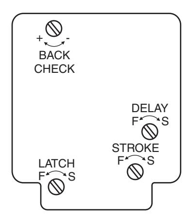
Closing speeds can be adjusted to suit local conditions and requirements. Label on closer face designates the purpose of each adjustment screw. Adjustments are for speed control.
- A. The stroke valve allows adjustment from open to 15°.
- B. The latch valve allows adjustment from 15° to closed position.
- C. IMPORTANT: Back check valve option must be adjusted to vary resistance from light to firm at 70° of door opening. FAILURE TO DO SO MAY RESULT IN DAMAGE TO THE CLOSER AND RELATED HARDWARE.
- D. The delay valve option allows closing speed adjustment from o en position to 65°. p
- E. This closer is
NON-HOLD-OPEN factory set, no hold open adjustment.
Note: With independently hung doors, on 53 closer, an auxiliary heavy duty door stop is required.
Repairs, parts replacement or internal adjustments must be done by a Rixson authorized repair agency. Consult www.rixson.com for an authorized repair agency in your area.

Rixson® is a registered trademark of Yale Security Inc., an ASSA ABLOY Group company. Copyright© 2005, 2009, Yale Security Inc., an ASSA ABLOY Group company. All rights reserved. Reproduction in whole or in part without the express written permission of Yale Security Inc. is prohibited.

5303-5305 Floor Closer
Offset Hung Single Acting Handed
ASSA ABLOY
Installation Instructions
5300 (06-09)
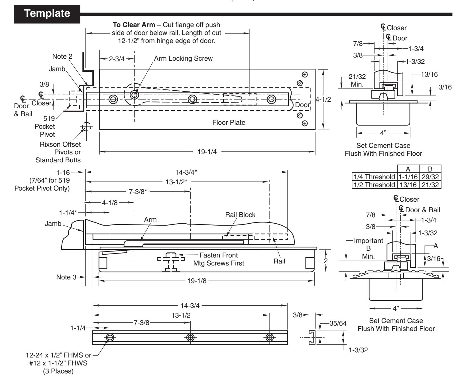
Notes:
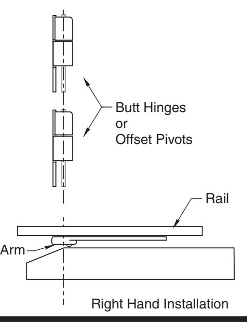
- 1. Right Hand Shown.
- 2. See pivot/hinge template for door configuration.
- 3. Rail to be 9/16" from hinge edge of door for 519 pivot only.
- 4. *Add 9/16" to these dimensions for 519 pivot only.
- 5. For additional template details for Rixson side jamb pivots refer to IP50050, for pocket pivot see IP50500 A & B.
- 6. Thresholds available on request (Rixson des gn Type 4). i
- 7. When threshold is used, door closer furnished must have a 1/2" longer spindle.
- 8. Auxiliary heavy duty door stop required.
- 9. Do not remove grind plate until closer is installed.
- 0. Dimensions are given in inches. 1
3/4" Offset Side Jamb Pivot 519 Pocket Pivot 5" Leaf Butt hinge 3/4" Offset Side Jamb Pivot 120 90 120 110 1-3/4" 2-1/4"
Thickness Hinge/Pivot Max Degree Opening 4", 4-1/2", 5" Leaf Butt Hinge
120
Consult factory for other door thickness, hinge/pivot sizes or extended spindle lengths.
DO NOT SCALE DRAWING
Conversion from inches to metric: inch x 25.4.
Rixson Specialty Door Controls www.rixson.com 866-474-9766 Technical Department Rixson Specialty Door Controls www.rixson.com 866-474-9766 Technical Department
Door
PAGE 2 PAGE 3
How To Determine Hand of Door
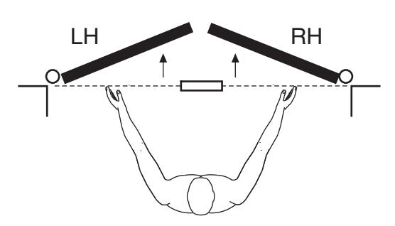
Face a door swinging open away from you. If it opens to the right, it is right hand. If it opens to the left, it is left hand.
IMPORTANT:
Use plumb line to make sure that center line of top pivot pin lines up with center line of closer spindle.
3. Hang Door
A. Mortise door and jamb for butts or pivots per template. (See template T-519 for pocket pivot.)
B. Install rail in door per template.
C. Secure rail in place and hang door. Use a plumb line to assure that door is in vertical alignment.
Installation Instructions
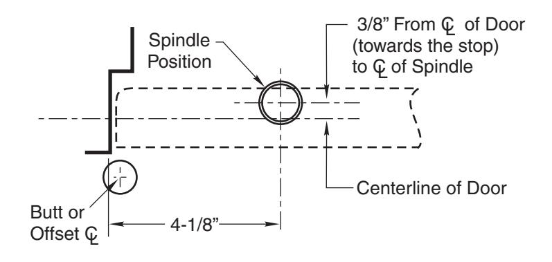
1. Locating Closer
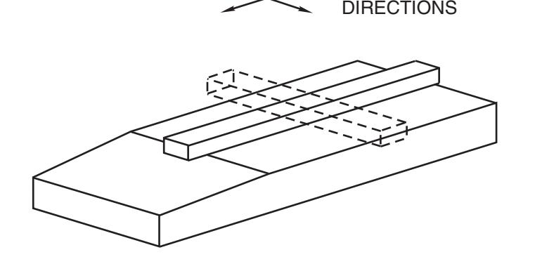
LEVEL IN BOTH
- A. Measure from push side of door 1/2 the thickness of the door to determine centerline of door.
- B. To determine centerline of closer measure back towards the stop side 3/8" from center line of door.
- C. Where the 4-1/8" and 3/8" measurements intersect indicate the centerline of closer spindle.
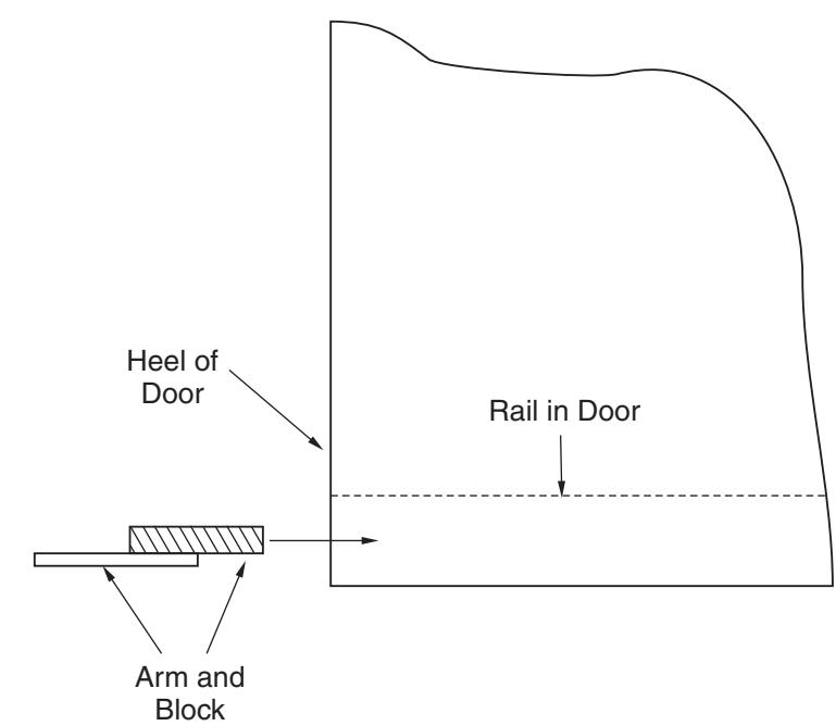
4. Attach Arm
-
- B. Slide arm block into rail through heel edge of door.
A. Close latch and stroke valves. (Turn Clockwise)
- C. With door almost closed slide arm onto spindle thru notch in end of arm. (Rock door back and forth to seat arm on spindle.)
- D. Secure arm to spindle with screw furnished. THE ARM SCREW MUST BE FASTENED SECURELY. (Tighten screw when rocking door back and forth.)
2. Install Cement Case in Floor
- A. Cement case is set flush with finished floor.
- B. Set cement case with closer in floor and block in position.
- C. Case should be parallel with center line of door.
- D. CEMENT CASE MUST BE LEVEL. Place levels per Illustration.
- E. Grout in cement case with closer. Cement should not get between closer and case.
- F. If centerline of closer needs position adjustment, loosen hold down screws (4) and reposition closer. Tighten hold down screws closest to spindle first then tighten screws at cylinder end. Note: Closer must be lifted approx. 1/8" before repositioning.
Rixson Specialty Door Controls Rixson Specialty Door Controls www.rixson.com 866-474-9766 Technical Department www.rixson.com 866-474-9766 Technical Department