Rixson 51QT Series Removable Floor Closer with Threshold 3-4 Offset Pivoted Handed Installation Instructions
Open the original PDF document
View PDFCloser Adjustment
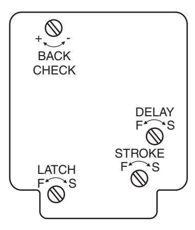
Closing speeds can be adjusted to suit local conditions and requirements. Label on closer face designates the purpose of each adjustment screw. Adjustments are for speed control.
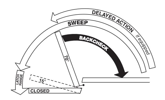
- A. The stroke valve allows adjustment from open to 15°.
- B. The latch valve allows adjustment from 15° to closed position.
- C. IMPORTANT: Back check valve option must be adjusted to vary resistance from light to firm at 70° of door opening.
- D. The delay valve option allows closing speed adjustment from o en position to 65°. p
Repairs, parts replacement or internal adjustments must be done by a Rixson authorized repair agency. Consult www.rixson.com for an authorized repair agency in your area.
Closer Removal or Reinstallation
Before removing or installing closer, close down valve screws. When reinstalling, lock closer in hold-open position if provided.
Closer Removal:
- 1. Remove thru-bolts, arm cap and loosen arm locking screw.
- 2. Open door to hold-open or (approx.) 90° and close. (If non hold-open is being removed, insert a flat blade (10" min) screwdriver between spindle and torque washer to prevent spindle from turning.)
- 3. Remove arm, shim and torque washer from spindle.
- 4. With door open, remove threshold.
- 5. Remove closer mounting screws (4) and slide closer out under door.
Closer Reinstallation:
Reverse above procedure when reinstalling closer.
Before attaching arm, closer spindle must be in hold-open or rotated to 90°. Non hold-open closers will require the use of a flat blade (10" min.) screwdriver For rotating the spindle.
Rixson® is a registered trademark of Yale Security Inc., an ASSA ABLOY Group company. Copyright© 2005, 2009, Yale Security Inc., an ASSA ABLOY Group company. All rights reserved. Reproduction in whole or in part without the express written permission of Yale Security Inc. is prohibited.

RIXSON ®
ASSA ABLOY
51QT Removable Floor Closer With Threshold
Installation Instructions 5100QT (06-09)
3/4" Offset Pivoted – Handed
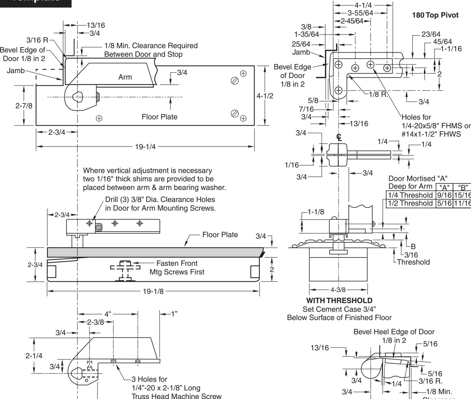
1-1/16 45/64
2
9/16 5/16 "A"
15/16 11/16 "B"

PAGE 4
Right Hand Shown
1-1/4
Conversion from inches to metric: inch x 25.4 Use only with 1-3/4" doors.
Maximum 11/16" clearance with standard spindle. Closer mounted flush with finished floor.
1-1/8 5" 4-1/4 4-5/8 5" 4-9/16 13/16 5/16 1-1/8 13/16 5/16
Door Leaf Jamb Leaf
3-9/16
1-15/16
2-1/2
1-7/16 3/8
Clearance
3-15/32
2-1/2
1-1/8 1-17/32
7/16
How To Determine Hand of Door
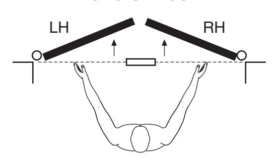
Face a door swinging open away from you. If it opens to the right, it is right hand. If it opens to the left, it is left hand.
Door Stop
1/8" Minimum From
Right Hand Door
-3/4" From Face
Spindle Position
13/16" From Face of
Jamb to of Spindle
of Door to C of Spindle
Face of Door to Door Stop
Installation Instructions
1. Install Closer
Door
Jamb
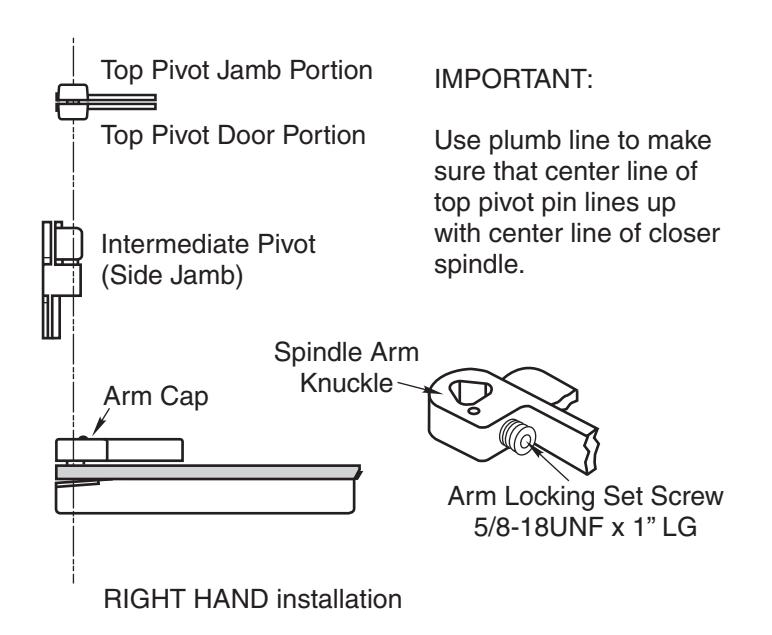
3. Install Top Pivot & Closer Arm
- A. Install top pivot in door per template.
- B. Install top pivot in frame per template.
- C. Center line of pivot should line up with center line of closer. Use plumb line as illustrated. If center lines don't line up, loosen hold down screws (4) and reposition closer. Tighten hold down screws closest
- to spindle first. Then tighten screws at cylinder end. Note: Closer must be lifted approximately 1/8" before repositioning.
- D. If side pivot is used, see template for intermediate
4. Hang Door
CAUTION: Closer is shipped with "closing speed" valve down. DO NOT FORCE VALVE DOWN.
- Remove styrofoam and metal plate from closer.
- Attach top pivot and closer arm to door.
- C. Attach top pivot to frame.
- Set door on closer spindle. DO NOT FORCE DOOR CLOSED WHILE "CLOSING SPEED" VALVE IS TURNED DOWN.
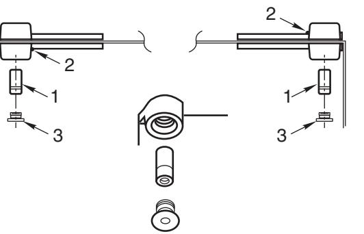
- E. Push item 1 "top pivot pin" into place. Attach "cap" item 3. (Illustration) CAP MUST BE TIGHTENED SECURELY.
- F. Install intermediate pivots. (See intermediate pivot
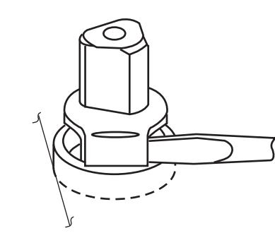
- G. Close door to 60° or more and turn valve screw counterclockwise. Door will then close.
- H. While working door back and forth TIGHTEN ARM LOCKING SCREW SECURELY with wrench furnished.
- Put arm cap on arm and secure TIGHTLY with cap screw furnished.
2. Install Cement Case in Floor
- A. For threshold application: Cement case is set 5/8" below floor level.
- B. Set cement case with styrofoam and closer attached in floor and block in position.
- C. Case should be parallel with center line of door.
A. Measure 13/16" out from door jamb.
face. Measure door thickness. Add 3/4".
B. Allow 1/8" minimum clearance from door stop to door
C. Where lines meet determines center line of closer.
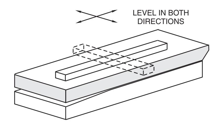
- D. CEMENT CASE SHOULD BE LEVEL. Place levels per illustration.
- E. Grout in cement case with closer and styrofoam attached. Cement should not get between closer and case.
Rixson Specialty Door Controls www.rixson.com 866-474-9766 Technical Department Rixson Specialty Door Controls www.rixson.com 866-474-9766 Technical Department