Restroom Kit and Emergency Kit Installation Instructions – I-EA00285-Rev01
Open the original PDF document
View PDF

DEVICES COVERED IN THIS DOCUMENT:
2-659-0240 2-659-0370 2-659-0371 2-659-0369 2-659-0374 2-659-0373
In order to simplify installation, the table below summarizes technical specifications, electrical box requirements, and suggested installation locations for the Restroom Kit and Emergency Kit components.
| COMPONENT | TECHNICAL SPECIFICATION | BOX 1 | LOCATION | |
|---|---|---|---|---|
| RESTROOM | Logic Module | 12 – 24 VAC/VDC ±10% see instruction I-EA00111 | N/A | inside door header |
|
"PUSH TO LOCK"
Button |
lamp C-656: 15 – 24 V, 0.06 A
lamp CM-161: 12 – 14 V, 0.19 A SPDT switch: 10 A @ 120 VAC / 28 VDC |
single-gang | inside restroom, near door | |
| Occupied Indicator |
12 – 24 VAC/VDC ±10%
jumper ON = SOUND (82dB @ 5V) jumper OFF = NO SOUND |
single-gang |
outside restroom,
near door |
|
| Door Position Switch | SPDT, 30 VAC/VDC, 0.25 A, 3.0 W gap distance: 2.0 in | N/A | on door | |
| EMERGENCY | Emergency Button |
12 – 24 VAC/VDC ±10%
DPDT switch: 10 A @ 24 VAC/VDC jumper ON = SOUND (82dB @ 5V) jumper OFF = NO SOUND |
double-gang |
inside restroom, near
toilet |
|
Assistance Required
Signal |
lamp #313: 28 VAC/VDC
sounder: 16 – 25 VAC/VDC, 15 mA |
single-gang |
outside restroom,
above door |
|
| Emergency Signage | N/A | N/A |
inside restroom,
above Emergency Button |
<sup>1</sup>Additional electrical boxes may be required for interior and exterior activation push plates.
INSTALLATION/SERVICE COMPLIANCE EXPECTATIONS
The sensor manufacturer cannot be held responsible for incorrect installations or inappropriate adjustments of the sensor/device; therefore, the sensor manufacturer does not guarantee any use of the sensor outside of its intended purpose.
The sensor manufacturer strongly recommends that installation and service technicians be AAADM-certified for pedestrian doors, IDA-certified for doors/gates, and factory-trained for the type of door/gate system.
Installers and service personnel are responsible for executing a risk assessment following each installation/service performed, ensuring that the sensor system installation is compliant with local, national, and international regulations, codes, and standards.
Once installation or service work is complete, a safety inspection of the door/gate shall be performed per the door/gate manufacturer recommendations and/or per AAADM/ANSI/DASMA guidelines (where applicable) for best industry practices. Safety inspections must be performed during each service call – examples of these safety inspections can be found on an AAADM safety information label (e.g. ANSI/DASMA 102, ANSI/DASMA 107).
Verify that all appropriate industry signage and warning labels are in place.


Rev 01 Page 1 of 1 Rev Date: 09/28/2020

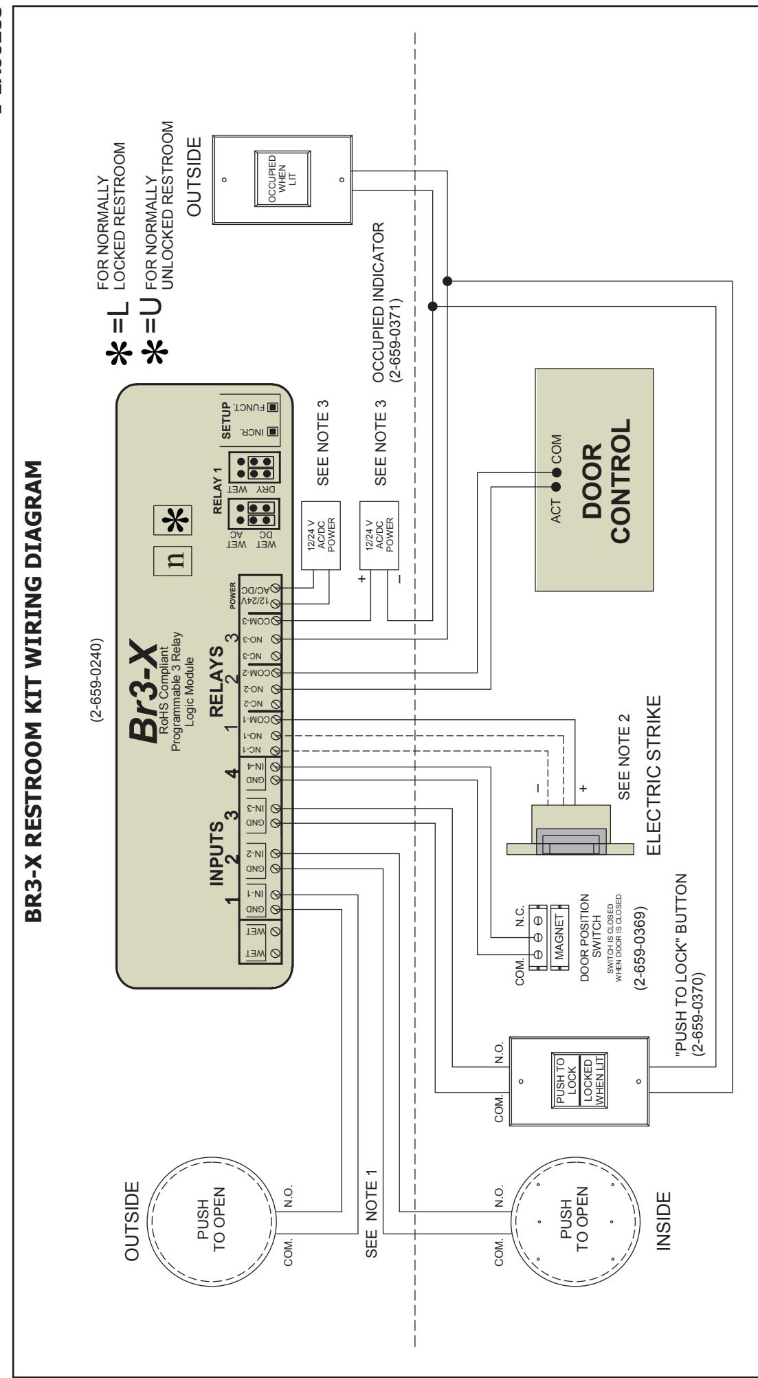
1) FOR INPUTS 1 & 2 ANY "DRY" CONTACT ACTIVATION DEVICE MAY BE USED
NOTES:
2) FAIL SAFE FOR NORMALLY UNLOCKED (WIRE N.O.) FAIL SECURE FOR NORMALLY LOCKED (WIRE N.C.)
3) ONE POWER SUPPLY CAN BE USED TO POWER ALL DEVICES.
4) KIT DOES NOT INCLUDE POWER SUPPLY, PUSH PLATES, ELECTRIC STRIKE OR DOOR CONTROL.
Page 2 of 4

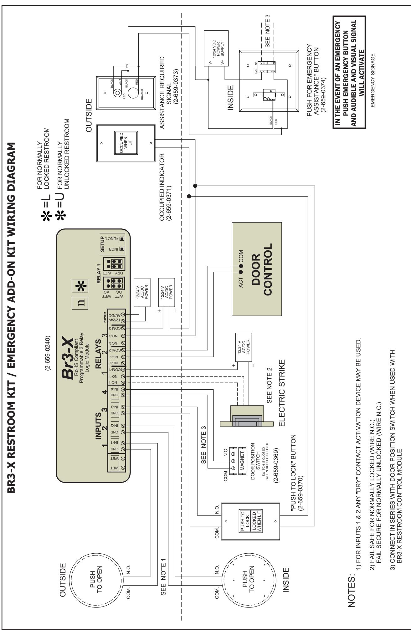
EMERGENCY ADD-ON KIT WIRING DIAGRAM
TECHNICAL SPECIFICATIONS
ARS Lamp #313: 28 VAC/VDC Sounder 16-25 VAC/VDC, 15mA
EBUTTONCOMBO 12-24 VAC/VDC +/- 10% JUMPER ON = SOUND JUMPER OFF = NO SOUND

1) CONNECT IN SERIES WITH DOOR POSITION SWITCH WHEN USED WITH BR3-X NOTES:
RESTROOM CONTROL MODULE
Rev XX
Page 3 of 4

Rev XX Rev Date: XX/XX/XXXX
Page 4 of 4