Request to Exit Installation Instructions – I-ED00368
Open the original PDF document
View PDF

4500 Series Electric Exit Devices Request to Exit (RX) Installation Instruction Grade 1 I-ED00368
DEVICES COVERED IN THESE INSTRUCTIONS:
RX Request to Exit
ELECTRICAL SPECIFICATIONS
Note: SPDT mechanical switch Wiring Diagram
Yellow Wire: (common)
Voltage Current 125 VAC 3 AMP 30 VDC 2 AMP Red Wire: (normally open) Grey Wire: (normally closed) Wire Gauge: #22 AWG
INSTALLATION INSTRUCTIONS
1. Remove chassis cover from device.
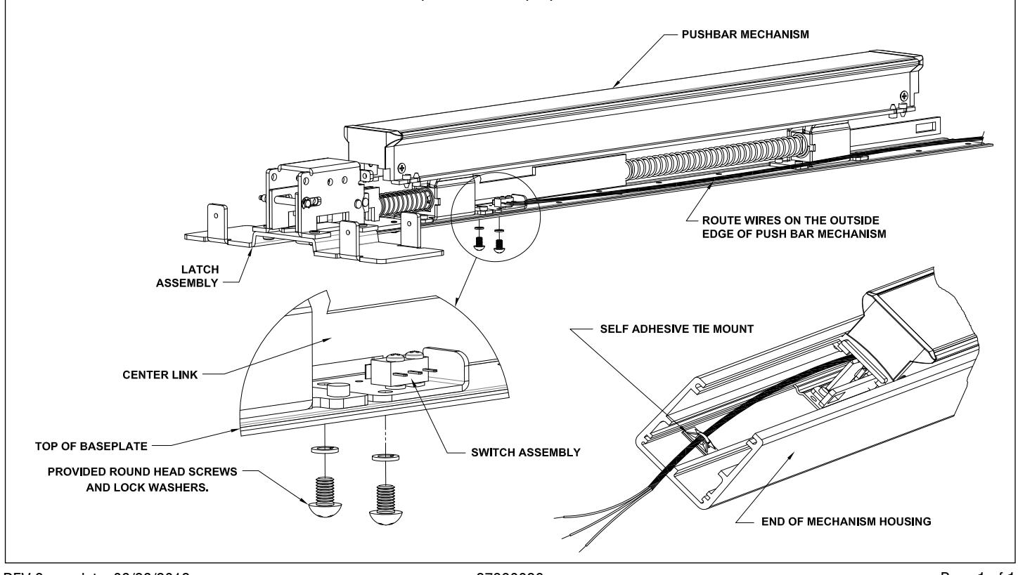
2. Separate pushbar and latch assembly from mechanism housing.
3. Place switch assembly into device as shown below. Assembly fits over top of existing holes.
4. Make sure switch arm is placed on outside of center link on the pushbar so that switch is pre-activated.
5. Use provided round head screws and lock washers to secure switch assembly to pushbar baseplate.
6. Check for proper switch activation--when pushbar is fully depressed switch should activate.
7. Run wires along outside edge of pushbar mechanism.
8. Re-assemble mechanism housing onto pushbar mechanism.
9. Secure self-adhesive tie mount holder to bottom of mechanism housing in end of device as shown below.
10. Make sure color code for wires is used for proper hook-up of switch contacts.
Note: See exit device instructions and template for door preparation.