Remote Switch Installation (3285, 3287 Status Switch)
Open the original PDF document
View PDFREMOTE SWITCH INSTALLATION - 550, 5100, 5800, 12-5800 SERIES
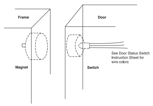
Door Status Switch (3287)
Maximum magnet to switch gap - 1/2" on steel, 3/4" on wood.
Door preparation: Drill 1/4" diameter access hole behind alarm unit
Drill 1" diameter hole for switch (1" deep) Drill 1/4" diameter hole for wires (solid door) Drill 1" diameter hole for magnet (1" deep)
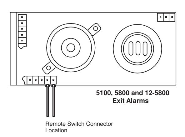
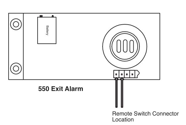
Refer to drawing for circuit board connections (pins 1, 2). Pull wires through access hole
and switch hole; mount alarm unit. Splice connector wires to switch wires; press switch and magnet into appropriate holes.
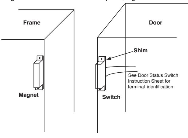
Surface Switch (3285)
Maximum magnet to switch gap-1/4" on steel, 3/4" on wood. Mount magnet as illustrated. Mount switch as illustrated, use 1/8" plastic shim for steel door. Refer to drawing for circuit board connections (pins 1, 2). Mount alarm unit; route wires along door surface (wires should be physically protected from tampering.) Cut and strip wire ends; attach to screw terminals. Loosen switch mounting screws and slide cover into place; tighten screws.

NOTE: Electrical noise may cause false alarms when input wires are routed near A.C. power wires, fluorescent lighting or A.C. motors. Two conductor-shielded wires should be used. It is not recommended that wire length exceed 15 feet.
Door Status Switch (3287) Contacts shown when magnet is in proximity with switch (door closed). Maximum current 250 ma.
Circuit Board Connections
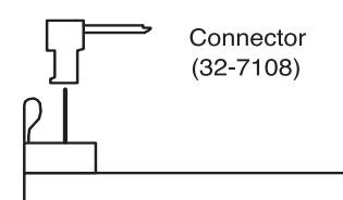
Connectors are directional and must be installed as illustrated. Wires are to be routed under the printed circuit board and through the access hole of the black plate.

Copyright © 2009, 2014, Sargent Manufacturing Company, an ASSA ABLOY Group company. All rights reserved. Reproduction in whole or in part without the express written permission of Sargent Manufacturing Company is prohibited.