ROFU Micro & Mini Magnetic Locks Installation Instructions
Open the original PDF document
View PDF

Installation Instructions ROFU Micro & Mini Magnetic Locks
8403M,F,S and 8406M ROFU *See page 3 for model specifications
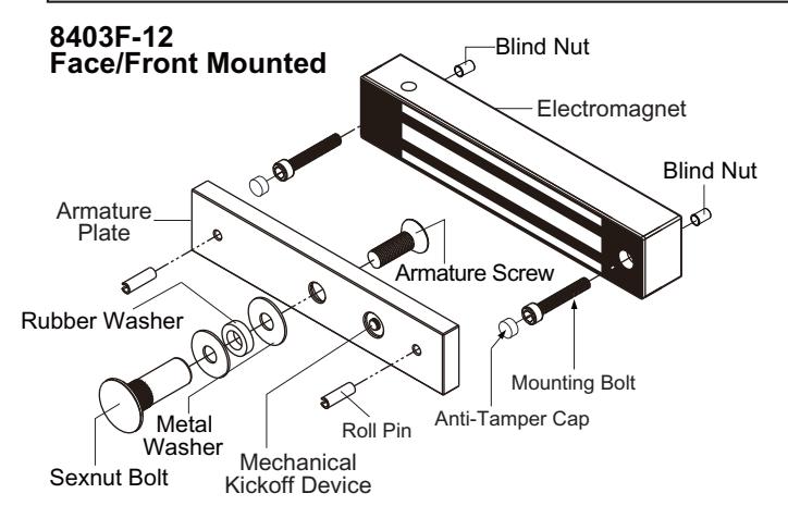
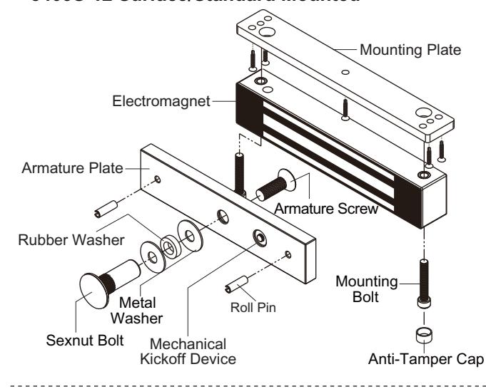
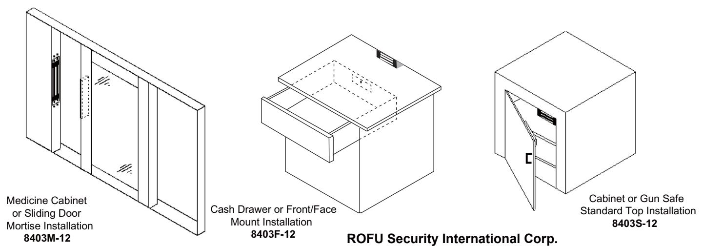
ROFU 8403 Micro Series Maglock with 300lbs of holding power and is designed for the application of a compact, specialized electromagnetic lock provides a higher level of security. Easy installation in small cabinets, drawers, lockers or restricted spaces. 8403M-12 is recommended for medicine cabinet or sliding door mortise installation. 8403F-12 is recommended for cash drawer standard top or front mount installation. 8403S-12 is standard surface mount which mounts like a standard magnet using a supplied mounting plate (#20918) and it is recommended for cabinet or gun safes standard top installation.
ROFU 8406M Mini Series Maglock is a compact mortise maglock with 600lbs of holding power with a steel housing. It is ideal for securing sliding or swinging, manual or automatic doors. Its durability for high frequency use and the lock mortised in the frame and the armature in the door, it secures the door in a closed position. When power is cut the lock releases instantly.
Note: Installation varies but intended for exterior usage, mounting holes thru the 8403S-12 Installations For Outswing Doors front of the magnetic lock.
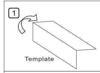
Find the paper installation template included with the magnet (you will need this).
Fold it on the dotted line.
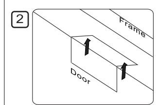
Place the folded template in the proper position on the door/jamb and mark the holes you will cut for your magnet and armature plate.

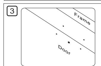
Drill the holes according to the marks you made.
(Check Twice! Drill Once!)..

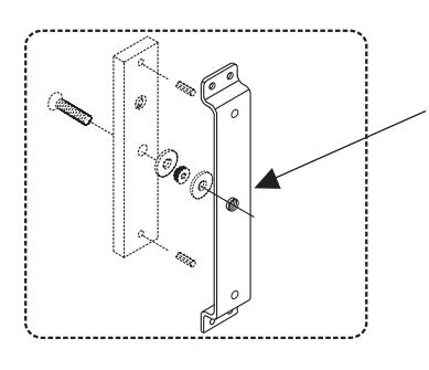
Install the armature plate as shown in the drawing to the left.
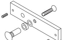
The actual dimensions of the holes are illustrated below.
Hollow Metal Door Solid Door
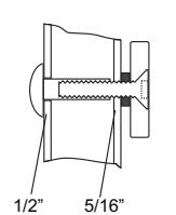
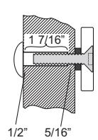
Drill a 5/16" (8mm) hole through the door for the armature side. For the sexnut side (secure side), enlarge the hole to 1/2" (12.7mm) for the width of the sexnut. On wood doors the depth of the sexnut is 1 7/16" (36mm).

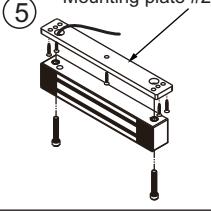
Attach the mounting plate to the jamb with the included Philips screws. Then use the thru-bolts to tighten the magnet to the mounting plate.
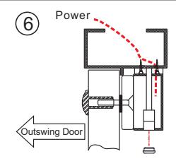
Connect the power and test the unit. Insert the anti-tamper caps into the screw holes in the magnet.
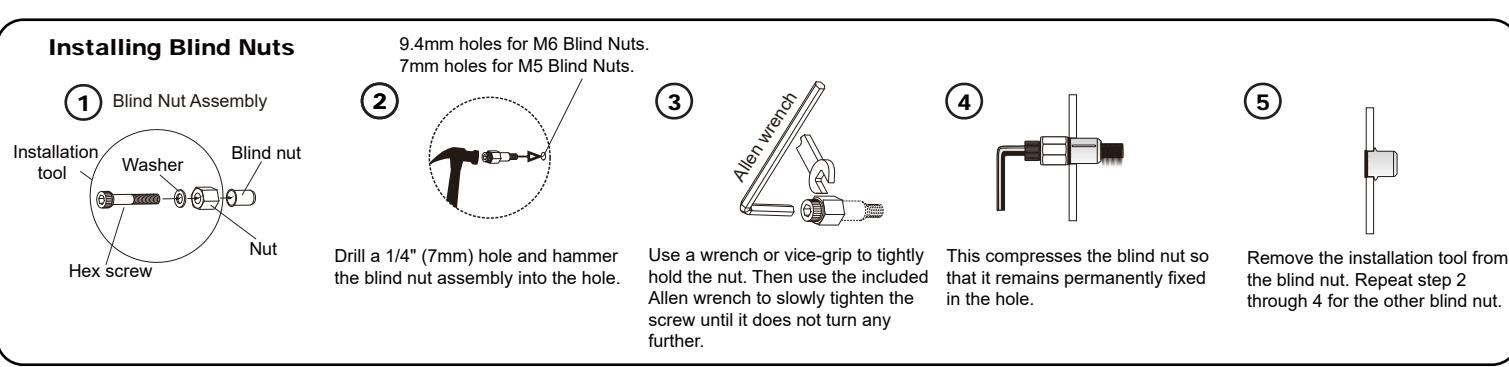
Installing the Crimp Connectors
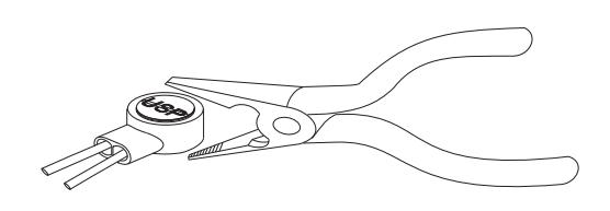
Place the wire inside the connector and use pliers to press down on the head of the connector evenly.
# 20925 Armature Bracket for 8406M Maglock
Mounting bracket #20925 is availalbe for mounting armature plate to wood door.
Installation Diagram & Screw Pack Components
Screw Package Components:
| - | on a manage components. | ||||||
|---|---|---|---|---|---|---|---|
| Roll Pin | Hexagon Key (Allen Wrench) | Rubber Washer | |||||
| ŀ | 5/32" x 5/8" | 2" x 5/8" x 2 5/32" and 3/16" x 1 | 3/8" x 9/16" x 3/16" | x 1 | |||
| ŀ | Metal Washer 5/16" x 5/8" x 2 | Anti-Tamper Cap | Thru-bolt (Hex Screw) | ||||
| 9 | |||||||
| ſ | 3/8" | x 2 | 3/16" x 1 3/16" | x 1 | |||
| Ī | Blind Nut Assembly | Blind Nut | Allen Flat Head Screw | ||||
| 3/16" x 1 3/16" | 16" x 1 3/16" x 1 3/16" x 1 | 5/16" x 1" | x 1 | ||||
8403S-12 Surface/Standard Mounted
Screw Package Components:
| Roll Pin | Hexagon Key (Allen Wrench) | ||||
| x 2 | 5/32" and 3/16" | x 1 | 3/8" x 9/16" x 3/16" | x 1 | |
| crew | Allen Flat Head Screw | Metal Washer | |||
| R. Mandalla Barrier | 0 | ||||
| 3/16" x 1" x 6 | x 1 | 5/16" x 5/8" | x 2 | ||
| Anti-Tamper Cap | Thru-bolt (Hex Screw) | Sexnut Bolt | |||
| 9 | 0 | ||||
| 3/8" x 2 | x 2 | 1/2" x 1 5/8" | x 1 | ||
| x 6 | x 2 5/32" and 3/16" Trew Allen Flat Head Screen x 6 5/16" x 1" Thru-bolt (Hex Screen | x 2 5/32" and 3/16" x 1 trew Allen Flat Head Screw x 6 5/16" x 1" x 1 Thru-bolt (Hex Screw) | x 6 5/16" x 1" x 1 5/16" x 5/8" Thru-bolt (Hex Screw) Sexnut Bolt | ||
8403M-12 and 8406M for Sliding Doors
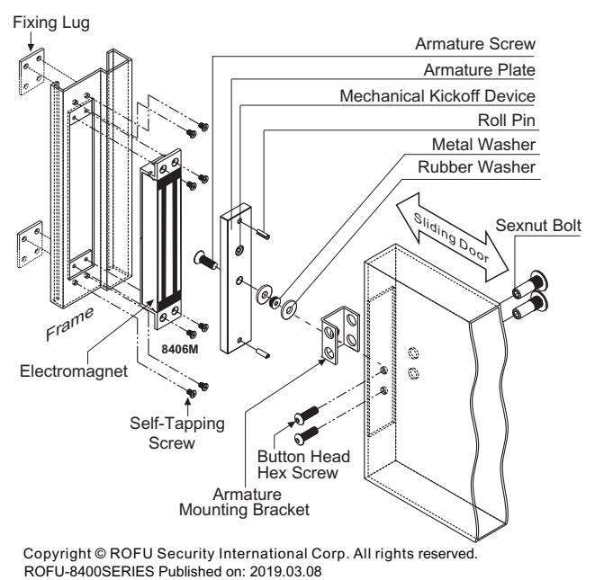
Screw Package Components: For 8403M-12 & 8406M:
| Roll Pin | Hexagon Key (Allen Wrench) | Rubber Washer | ||||
| 5/32" x 5/8" x 2 | 3/16" | x 1 | 3/8" x 9/16" x 3/16" | x 1 | ||
| Allen Flat Head Screw 5/16" x 1" x 1 | Button Head Hex Screw | |||||
| 5/16" x 1" | x 2 | |||||
For 8403M-12 Only:
| Fixing Lug | Philips Flat Head Screw | ||
|---|---|---|---|
| 00 | |||
| 1 3/8" x 1 1/4" x 1/16" | x 2 | 3/16" x 1/4" | x 8 |
For 8406M Only:
| Fixing Lug | Philips Flat Head Screw | Metal Washer | |||
|---|---|---|---|---|---|
| 0 | |||||
| 1 5/8" x 1 1/2" | x 2 | 3/16" x 5/16" | x 10 | 5/16" x 7/8" | x 2 |
| Model | 8403F-12 | 8403S-12 | 8403M-12 | 8406M | |||
|---|---|---|---|---|---|---|---|
| Holding Force | 300lbs | 300 lbs | 300 lbs | 600lbs | |||
| Operating Voltage | 12VDC | 12VDC | 12 VDC | 12/24VDC | |||
| Current Draw | 300mA/12VDC, 260mA/24VDC | 300mA/12VDC, 260mA/24VDC | 300mA/12VDC, 260mA/24VDC | 500mA/12VDC, 250mA/24VDC | |||
| Operating Temperature | 14°F~131°F (-10°C~55°C) | ||||||
| Magnet |
6 11/16"(L) x 1 1/4"(H) x 15/16"(W)
(170 x 32 x 23.7mm) |
6 11/16"(L) x 1 1/4"(H) x 15/16"(W)
(170x 32x 23.7mm) |
7 7/8"(L) x 1 1/4"(H) x 15/16"(W)
(200 x 32 x 24mm) |
9 1/16"(L) x 1 1/2"(H) x 1 1/16"(W)
(230 x 38 x 27mm) |
|||
| Dimensions |
Armature
Plate |
6"(L) x 1 1/4"(H) x 3/8"(W)
(152 x 32 x 10mm) |
6"(L) x 1 1/4"(H) x 3/8"(W)
(152 x 32 x 10mm) |
6"(L) x 1 1/4"(H) x 3/8"(W)
(152 x 32 x 10mm) |
7 1/4"(L) x 1 1/2"(H) x 1/2"(W)
(185 x 38 x 12mm) |
||
| Frame | Wood, Hollow Metal | ||||||
| Finish | US28 Satin Aluminum | ||||||
| Installation |
Indoor use, Face/Front
Indoor use, Surface/Standard Indoor use, Mortise mounted, mounted mounted For sliding doors |
Indoor use, Mortise mounted,
For sliding doors |
|||||
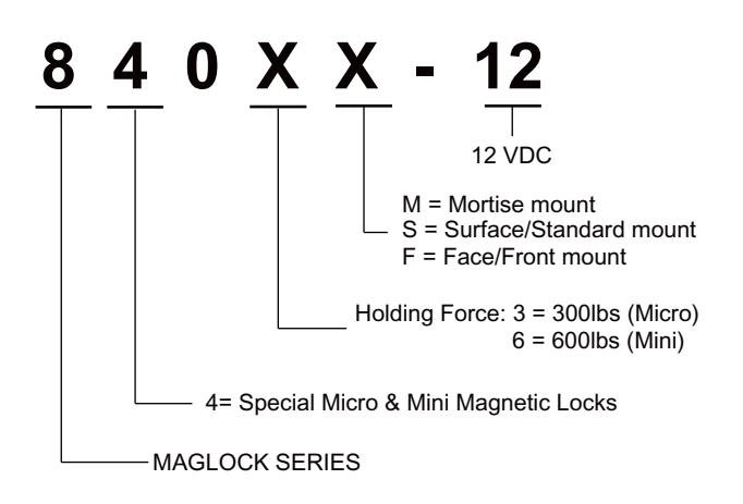
Model Changes to ROFU Special Micro & Mini Magnetic Locks
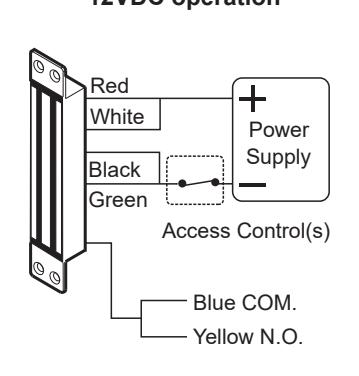
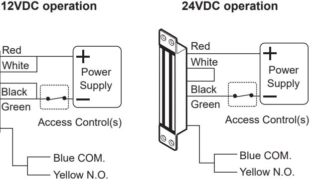
Wiring Diagram for 8406M
Applications
Copyright © ROFU Security International Corp. All rights reserved. ROFU-8400SERIES Published on: 2019.03.08
6818 S 220th ST Kent, WA 98032 (253) 922-1828 www.ROFU.com OrderEntry@ROFU.com