ROFU Keyswitch Installation Instructions
Open the original PDF document
View PDF

ROFU Keyswitch Installation Instructions for ROFU models 9200,9210, 9220 & 9230 Momentary/Maintained
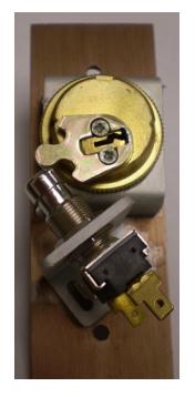
- 1. Remove parts from the box and place your mortise cylinder through the hole in the cover plate and the cylinder bracket. The teeth should slide around the grooves. The bracket should drop into the groves in the rear of the plate, fasten with the ring nut.
- 2. Depending on the type of cam, choose 2 of the 3 holes for the screw mounting of switch bracket mount at an angle mount for straight cams or horizontally for clover cams.
- 3. Install switch in bracket and bracket to plate, do not completely tighten, switch may be vertically adjusted with switch nuts.
- 4. Insert Key into cylinder and rotate until cam pushes down on switch and audible click is heard. Tighten all screws and nuts now. Counterclockwise rotation of key should not allow straight cam to strike switch plunger
- 5. Check once more to ensure proper alignment.
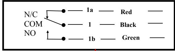
- 6. Slide color coded connector/leads over terminals on switch according to diagram, depending on fail secure or fail safe system.
- 7. Wire nuts leads to wires of appliance (electric lock etc) check for proper operation.
- 8. Fasten plates to electric utility box (mortise or surface type) with spanner head screws (wrench supplied).
- 9. If you discover that the NC on the maintained switch is not working as NC, please push the button then try it again
ROFU International Corp 1-800-255-7638 www.rofu.com
9970 Momentary Metal Button
NC is on the left. COM is in center. NO is on the right. NC/COM or NO are not marked on either models.
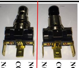
9971 Maintained Black Button