ROFU Key Hole Mount Magnetic Locks Installation Instructions
Open the original PDF document
View PDF

for ROFU Key Hole Mount Magnetic Locks Installation Instructions
8508-LC, 8508-B, 8512-LC, 8512-B, 8512-2-LC, 8512-2-B, 8512-20993
*See page 2 for model specifications
ROFU Security International Corp. 10029 S. Tacoma Way, E-11 Lakewood, WA 98499 USA 1-800-255-7638 (1-800-ALL-ROFU) www.ROFU.com OrderEntry@rofu.com
For Outswing Doors
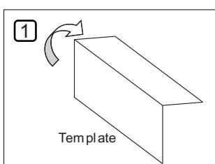
Find the paper installation template included with the magnet (you will need this).
Fold it on the dotted line.
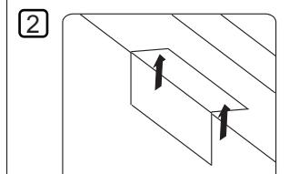
Place the folded template in the proper position on the door/jamb and mark the holes you will cut for your magnet and armature plate. (Using tape will help)
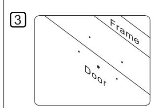
Drill the holes according to the marks you made.
(Check Twice! Drill Once!)..

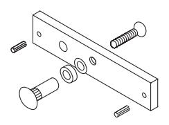
Armature Plate Install the armature plate as shown in the drawing to the left.
The actual dimensions of the holes are illustrated below.
Hollow Metal Door Solid Door
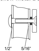
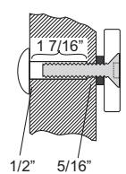
Drill a 5/16" (8mm) hole through the door for the armature side. For the sexnut side (secure side), enlarge the hole to 1/2" (12.7mm) for the width of the sexnut.
On wood doors the depth of the sexnut is 1 7/16" (36mm).
5
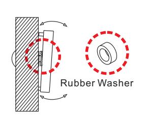
The rubber washer helps the armature plate to pivot. As it should NOT be tightened all the way to door.
6
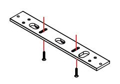
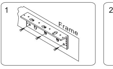
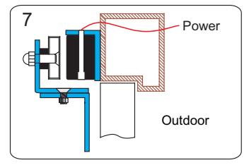
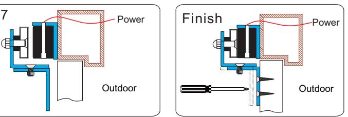
Attach the mounting plate to the jamb and tighten the mounting screws.

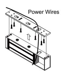
Pass the wiring through the mounting plate and into the wiring hole at the top of the magnet and into the PCB area.
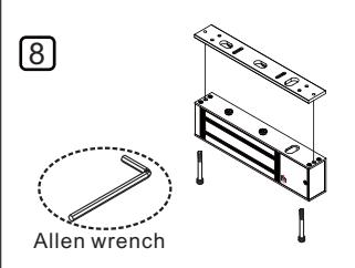
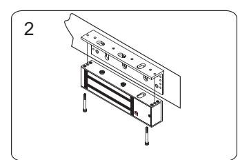
Attach the magnet to the mounting plate. Use the Allen wrench and thru-bolts to tighten the magnet to the mounting plate.
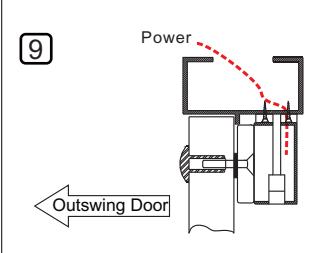
Connect the power and test the holding force. Add washers if there is still a gap between the magnet and armature plate.
Attaching Magnet to Mounting Plate
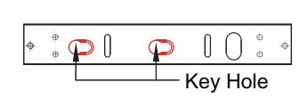
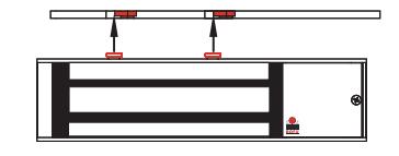
1. Align the two slotted holes and attach the magnet to the mounting plate.
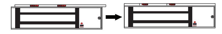
2. Slide the magnet onto the mounting plate.
Keyhole Mounting "slides Left to Right"
ROFU Z-bracket for Inswing Doors
Find the correct mounting position on the door jamb for the L-bracket. Ensure that the door still closes with it in position.
Use the thru-bolt to install the magnet onto the L-bracket.
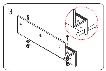
Assemble the Z-bracket, but not too tight as it needs to remain adjustable for now.
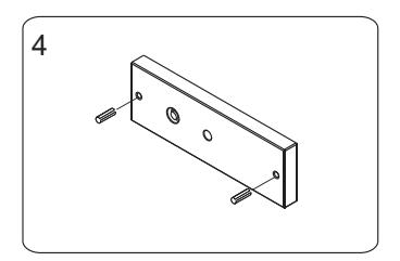
Insert the roll pins into the armature plate.
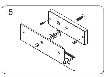
Attach the armature plate and washers to the Z-bracket assembly.
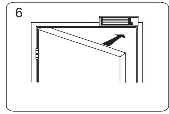
Close the door and connect the power.
After the magnet engages the armature plate, you can now adjust the Z-bracket, and attach to the door.
Ensure all screws of Z-bracket are tighten to door.
We encourage the use of thread locker (LocTite).
Specifications
Voltage: 12/24 VDC Selectable
Current Draw: 500mA/12VDC, 250mA/24VDC Holding Force: 800lbs, 1200lbs, 1200lbs x 2
Finish: US28, US40
Dimensions:
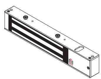
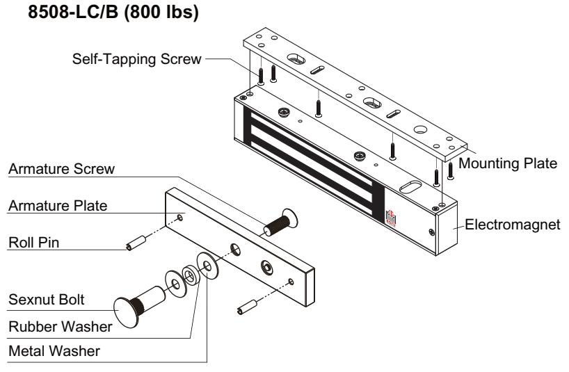
8508-LC/B (800 lbs)
Magnet: 10 7/16" x 1 7/8" x 1 1/8" (265 x 48 x 28.5mm) Armature Plate: 7 1/4" x 1 3/4" x 9/16" (185 x 45 x 14mm)
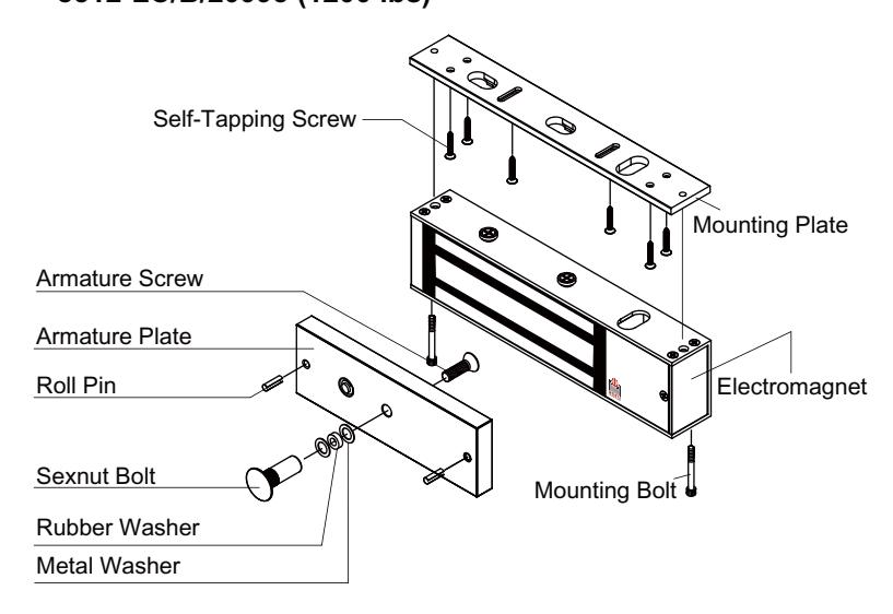
8512-LC/B/20993 (1200 lbs)
Magnet: 10 1/2" x 2 11/16" x 1 9/16" (267 x 68 x 40mm) Armature Plate: 7 1/4" x 2 3/8" x 5/8" (185 x 61 x 16mm)
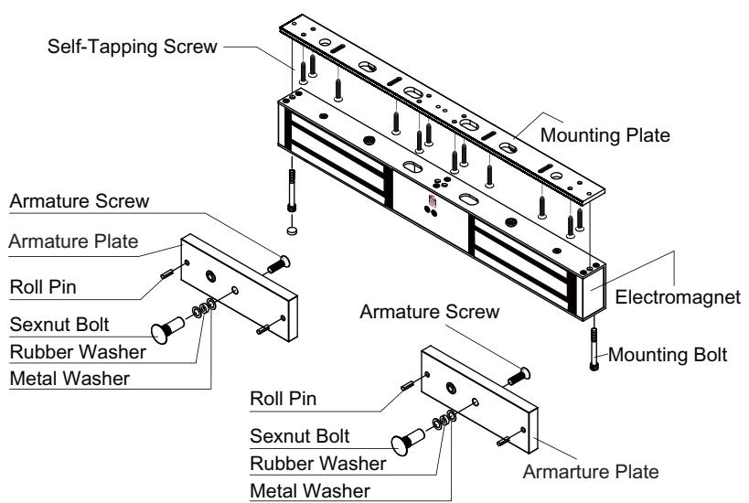
8512-2-LC/B (1200 lbs x 2)
Magnet: 21" x 2 5/8" x 1 9/16" (533 x 67 x 40mm) Armature Plates (each side): 7 1/4" x 2 3/8" x 5/8" (185 x 61x 16mm)
Model Changes to ROFU Electromagnetic Locking Devices

12/24: 12/24 VDC Selectable
Finish:
US40 Duronatic / Dark Anodized Bronze US28 Satin Aluminum or
(Limited Availability for US40)
Functions:
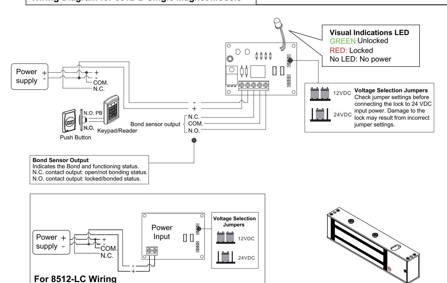
B = Bond sensor & LED only LC = Low cost (NO MONITORING)
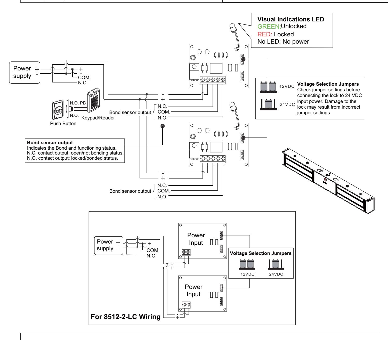
2 = Double magnet OR NOTHING THERE
Holding Force:
08 = 800 lbs (Midi)
12 = 1200 lbs (Standard)
5 = Keyhole mounting plate magnetic lock series
MAGLOCK SERIES
Troubleshooting
| Problem | Possible Cause | Solution |
|---|---|---|
| Magnet does not lock | No power |
- Ensure all wires are connected properly.
- Check that the power supply is connected and works properly. - Ensure the REX is wired in Common and out the N/C position. |
| Low holding force |
Poor contact between magnet and
armature plate |
- Is the armature plate warped?
- Ensure the armature plate is loose enough to be able to "pivot" and bond with the magnet - Ensure the surface of the magnet and armature plate are clea-use a soft cloth and a spray lubricant to clean it. - Are you using rubber washer on end of through bolt? |
|
*Please remember to test
with the armature plate, not a screwdriver. |
Low voltage or incorrect voltage
setting |
- Check the mag lock and ensure it is set for correct voltage.
Check the voltage at the magnet input, if low-determine if you're using the correct gauge of double stranded wire. This will prevent excessive line (voltage) drop. |
|
Sensor output is
not functioning |
A second diode was installed
across the electromagnetic lock |
- Remove any diode installed across the magnet for "spike"
suppression. (The magnet has a metal oxide varistor to prevent back EMF) |
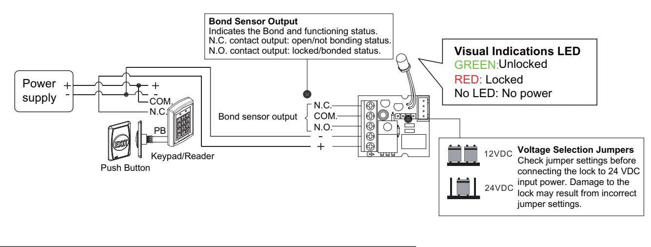
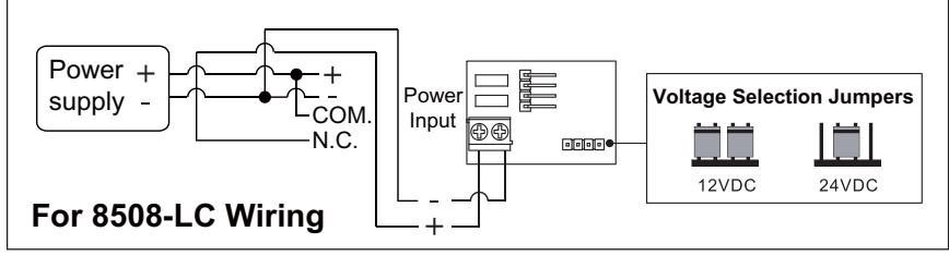
Wiring Diagram for 8512-B Single Magnet Models
- ROFU recommends a good maintenance schedule!
- Please ensure all armature bolts and mounting bolts are checked quarterly.
- ROFU recommends using Loctite (Thread locker) on ALL BOLTS during installation.
- Current Draw: 500mA/12VDC, 250mA/24VDC per block
ROFU Security International Corp. 10029 S. Tacoma Way, E-11 Lakewood, WA 98499 USA 1-800-255-7638 (1-800-ALL-ROFU) www.ROFU.com OrderEntry@rofu.com
Optional Features/Accessories:
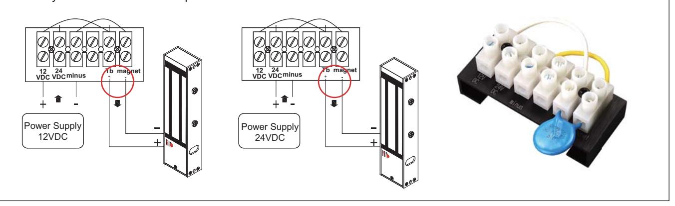
Model 8512-20993 , this is known as an "Oklahoma Special"
We add a terminal block to the standard 8512-LC which is known better to handle the electrical stormsthat are so well known in the Oklahoma region. This magnet has become a standard install in most commercial buildings, casinos and facilities in the state of Oklahoma, not only for the ease of installation, but the ease of wiring with theterminal block and the proven durability and reliability of this model to stand up to the harsh electrical storms in the area.
ROFU Security International Corp. 10029 S. Tacoma Way, E-11 Lakewood, WA 98499 USA 1-800-255-7638 (1-800-ALL-ROFU) www.ROFU.com OrderEntry@rofu.com
Screw Package Components:
| Roll Pin | Hexagon Key (Allen Wrench) | Rubber Washer | |||||
|---|---|---|---|---|---|---|---|
| 3/16" x 5/8" | x 2 | 3/16" | x 1 | 11/32" x 19/32" x 5/32" | x 1 | ||
| Allen Flat Head Screw | Philips Flat Head Screw | Metal Washer | |||||
| 5/16"x 1 3/8" | x 1 | 3/16" x 1 1/4" | x 6 | 5/16" x 7/8" | x 4 | ||
| Sexnut Bolt | |||||||
| 1/2" x 1 9/16" | x 1 | ||||||
8512-LC/B/20993 (1200 lbs)
Screw Package Components:
| Roll Pin | Hexagon Key (Allen Wrench) | Rubber Washer | |||
| 3/16" x 5/8" | x 2 | 3/16" | x 1 | 11/32" x 19/32" x 5/32" | x 1 |
| Allen Flat Head Screw | Philips Flat Head Screw | Thru-Bolt (Hex Screw) | |||
| 5/16"x 1 3/8" | x 1 | 3/16" x 1 1/4" | x 6 | 1/4" x 1 9/16" | x 2 |
| Metal Washer | Sexnut Bolt | ||||
| 5/16" x 7/8" | x 3 | 1/2" x 1 9/16" | x 1 | ||
8512-2-LC/B (1200 lbs x 2)
Screw Package Components:
| Roll Pin | Hexagon Key (Allen Wrench) | Rubber Washer | ||||
|---|---|---|---|---|---|---|
| 3/16" x 5/8" | x 4 | 3/16" | x 1 | 11/32" x 19/32" x 5/32" | x 2 | |
| Allen Flat Head Screw | Philips Flat Head Screw | Thru-Bolt (Hex Screw) | ||||
| 5/16"x 1 3/8" | x 2 | 3/16" x 1 1/4" | x 12 | 1/4" x 1 9/16" | x 4 | |
| Metal Washer | Sexnut Bolt | |||||
| 5/16" x 7/8" | x 6 | 1/2" x 1 9/16" | x 2 | |||