ROFU Electric Strikes 1402, 1702, 3402 Aluminum Jamb Installation Instructions
Open the original PDF document
View PDF

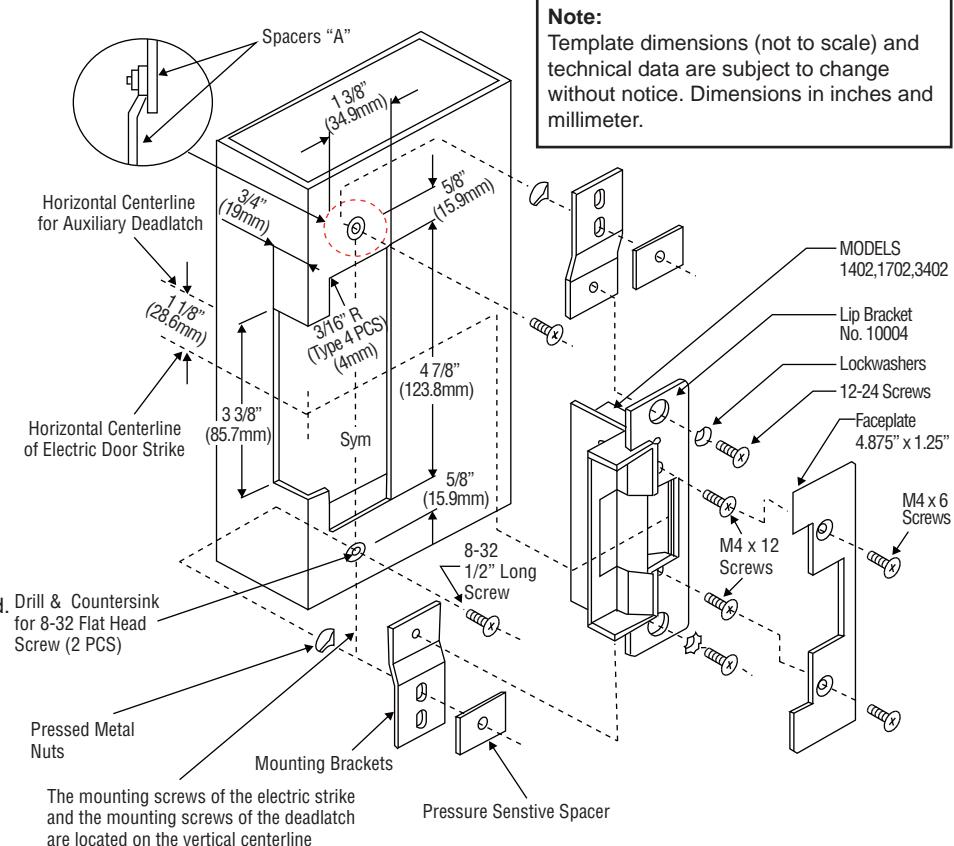
ROFU Electric Strikes 1402, 1702, 3402 Aluminum Jamb
Installation Instructions:
- 1. Prepare door jamb per drawing
- Install mounting brackets to jamb using 8-32 ½" screws and pressed metal nuts. Do not tighten.
- 3. Spacers are provided to assure flush final assembly of faceplates into jamb. Add one or more spacers between jamb mounting bracket when faceplate extends beyond the jamb. When the faceplate sets inside the jamb spacers must be added between the mounting bracket and the lip bracket. See detail 'A'. Make sure clearance hole in spacer aligns with hole in mounting bracket.
- 4. Connect wires coming from the low voltage side of the transformer to terminal block of door strikes.
- Install electric door strike to jamb attaching with 12-32 screws and lockwashers or 12-24 screws furnished. Drill & Countersink
- 6. Attach faceplate using M 4X4 or M 4X6 screws furnished.
- 7. Secure 5-32 screws holding mounting bracket to jamb.
Note:
For mortise lockset with auxiliary deadlatch:
To secure that the latchbolt falls properly into the keeper, the centerline of the auxiliary deadlatch must be 1-1/8" above (or below when application) the centerline of the strike. Before installation make sure that the FA/FIX part is moved to the outside of the lip bracket.
ROFU Security International Corp. 10029 S. Tacoma Way, E-11 Lakewood, WA 98499 1-800-255-7638 / www.ROFU.com / OrderEntry@ROFU.com

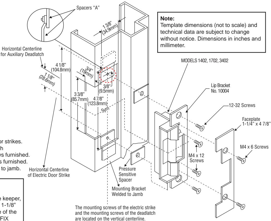
ROFU Electric Strikes 1402, 1702, 3402 Hollow Metal Jamb
Installation Instructions:
- 1. Prepare door jamb per drawing
- Install mounting brackets to jamb using 8-32 ½" screws and pressed metal nuts. Do not tighten.
- 3. Spacers are provided to assure flush final assembly of faceplates into jamb. Add one or more spacers between jamb mounting bracket when faceplate extends beyond the jamb. When the faceplate sets inside the jamb spacers must be added between the mounting bracket and the lip bracket. See detail 'A'. Make sure clearance hole in spacer aligns with hole in mounting bracket.
- 4. Connect wires coming from the low voltage side of the transformer to terminal block of door strikes.
- Install electric door strike to jamb attaching with 12-32 screws and lockwashers or 12-24 screws furnished.
- 6. Attach faceplate using M 4X4 or M 4X6 screws furnished.
- 7. Secure 5-32 screws holding mounting bracket to jamb.
Note:
For mortise lockset with auxiliary deadlatch:
To secure that the latchbolt falls properly into the keeper, the centerline of the auxiliary deadlatch must be 1-1/8" above (or below when application) the centerline of the strike. Before installation make sure that the FA/FIX part is moved to the outside of the lip bracket.
ROFU Security International Corp. 10029 S. Tacoma Way, E-11 Lakewood, WA 98499 1-800-255-7638 / www.ROFU.com / OrderEntry@ROFU.com

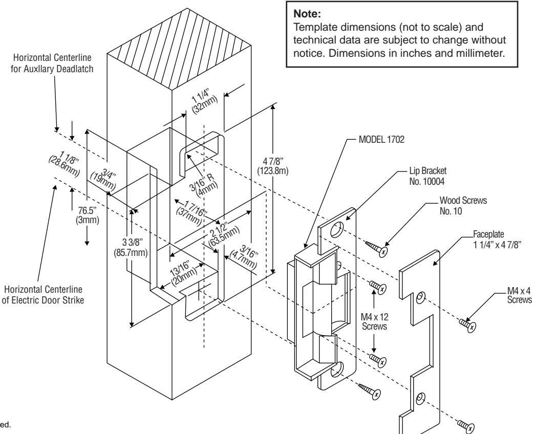
ROFU Electric Strike 1702 Wood Jamb
Installation Instructions
- 1. Prepare door jamb per drawing.
- Connect wires coming from the low voltage side of the transformer to terminal block of door strikes.
- 3. Install electric door strike to jamb attaching with #10 wood screws.
- 4. Attach faceplate using M 4X4 screws.
Note:
For mortise lockset with auxiliary deadlatch: To secure that the latchbolt falls properly into the keeper, the centerline of the auxiliary deadlatch must be 1-1/8" above (or below when application) the centerline of the strike. Before installation make sure that the FA/FIX part is moved to the outside of the lip bracket.
ROFU Security International Corp. 10029 S. Tacoma Way, E-11 Lakewood, WA 98499 1-800-255-7638 www.ROFU.com
OrderEntry@ROFU.com
Copyright © ROFU Security International Corp. All rights reserved. ROFU-1702 Published on: 2016.08.17