ROFU Door Handle Maglocks 8106HD Series Installation Instructions
Open the original PDF document
View PDF

Installation Instructions for the ROFU Pull Handle Models: 8106HD Series Magnetic Locks
ROFU Security International Corp.
6818 S 220th ST Kent, WA 98032 (253) 922-1828 www.ROFU.com OrderEntry@ROFU.com
Specifications
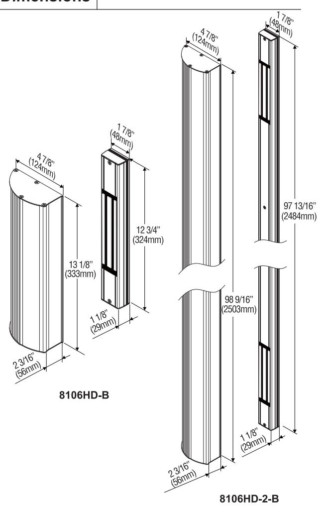
| Model | 8106HD-B | 8106HD-2-B |
|---|---|---|
| Operating Voltage | 12/24VDC |
12/24VDC
(each side) |
| Current Draw |
500mA/12VDC,
250mA/24VDC |
500mA/12VDC,
250mA/24VDC (each side) |
| OperatingTemperature | -10~55°C(14~131°F) | |
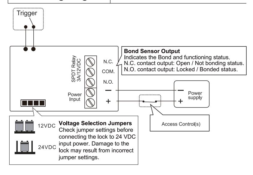
| Bond Sensor Output | 3A/12VDC |
3A/12VDC
(each side) |
| Holding Force | 600 lbs (272Kg) |
600 lbs (272Kg)
(each side) |
| Finish | US28 | |
Dimensions
Connecting Diagram
Installation Instructions
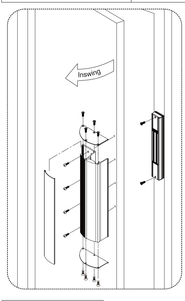
- Close the door and make sure the door and door frame are on the same level. Add additional plate spacers if needed.
- 2. Place the template in the proper position on the door and frame.
- 3. Drill holes for cable access and blind nuts according to the template.
- 4. Install blind nuts to secure the magnetic lock assembly.
- Secure the armature plate assembly. Connect the power wires and test the holding force. Add rubber washers if there is still a gap between the armature plate and magnet.
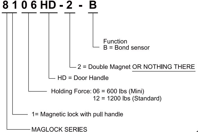
Model Changes to ROFU Electromagnetic Locking Devices
Installation Diagram & Screw Pack Components
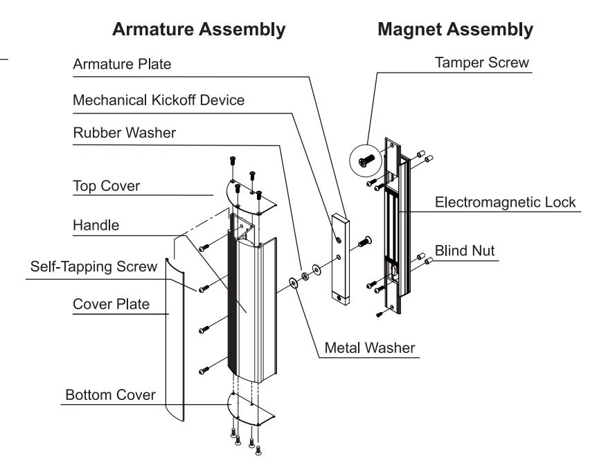
| Components | 8106HD-B | 8106HD-2-B |
|---|---|---|
| Blind Nut Assembly |
x 1
(1/4"x 1 3/8") |
x 1
(1/4"x 1 3/8") |
| Blind Nut |
x 7
(1/4") |
x 16
(1/4") |
|
Hexagon Key
(Allen Wrench) |
(5/32") x 1
(3/16") x1 |
x 1
(3/16") |
| Torx Wrench |
x 1
(5/32") |
x 1
(5/32") |
| Thru-bolt (Button Head Hex Screw) |
x 8
(1/4" x 5/8") |
x 17
(1/4" x 5/8") |
| Philip Flat Head Screw | _ |
x 8
(5/32 x 1/2") |
Installing Blind Nuts

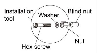
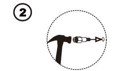
Drill a 3/8" (9.4mm) hole and hammer the blind nut assembly into the hole.
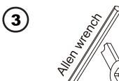
Use a wrench or vice-grip to tightly hold the nut. Then use the included Allen wrench to slowly tighten the screw until it does not turn any further.
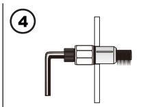
This compresses the blind nut so that it remains permanently fixed in the hole.
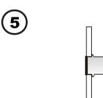
Remove the installation tool from the blind nut. Repeat step 2 through 4 for the other blind nuts.
Trouble Shooting
| Problem | Possible Cause | Solution |
|---|---|---|
| Magnet does not lock | No power | - Ensure all wires are connected properly. - Check that the power supply is connected and works properly. - Ensure the REX is wired in Common and out the N/C position. |
| I ow holding force | Poor contact between magnet and armature plate | - Is the armature plate warped? - Ensure the armature plate is loose enough to be able to "pivot" and bond with the magnet. - Ensure the surface of the magnet and armature plate are clean. - Use a soft cloth and a spray lubricant to clean it. - Are you using rubber washer on end of through bolt? |
| Low voltage or incorrect voltage setting | Check the mag lock and ensure it is set for correct voltage. Check the voltage at the magnet input, if low-determine if you're using the correct gauge of double stranded wire. This will prevent excessive line (voltage) drop. | |
| Sensor output is not functioning | A second diode was installed across the electromagnetic lock | - Remove any diode installed across the magnet for "spike" suppression. (The magnet has a metal oxide varistor to prevent back EMF) |