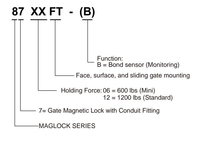
ROFU 8712FT Series Gate Magnetic Locks with Conduit Fitting Installation Instructions
Open the original PDF document
View PDF

Installation Instructions ROFU Gate Magnetic Locks with Conduit Fitting
8706FT and 8712FT Series (Face, Surface, and Sliding Gate Mount) *See page 5 for model specifications
ROFU Security International Corp. 10029 S. Tacoma Way, E-11 Lakewood, WA 98499 USA 1-800-255-7638 (1-800-ALL-ROFU) www.ROFU.com OrderEntry@ROFU.com

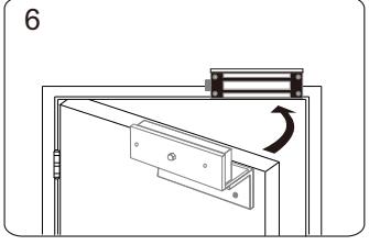
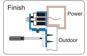
For Outswing Gates
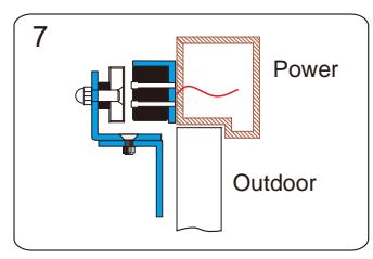
Note: Installation varies but intended for exterior usage, mounting holes thru the front of the magnetic lock.
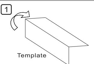
Find the paper installation template included with the magnet (you will need this).
Fold it on the dotted line.
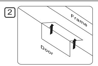
Place the folded template in the proper position on the gate and mark the holes you will cut for your magnet and armature plate. (Using tape will help)
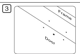
Drill the holes according to the marks you made.
(Check Twice! Drill Once!)..

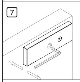
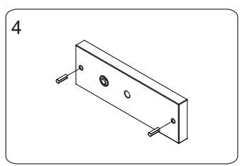
Install the armature plate as shown in the drawing to the left.
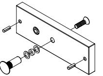
The actual dimensions of the holes are illustrated below.
Hollow Metal Gate Wooden Gate
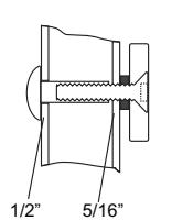
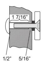
Drill a 5/16" (8mm) hole through the gate for the armature side. For the sexnut side (secure side), enlarge the hole to 1/2" (12.7mm) for the width of the sexnut. On wooden gate the depth of the sexnut is 1 7/16" (36mm).
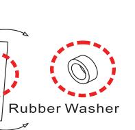
The rubber washer helps the armature plate to pivot. As it should NOT be tightened all the way to gate.
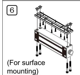
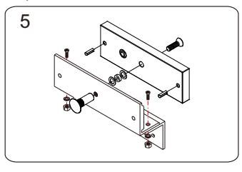
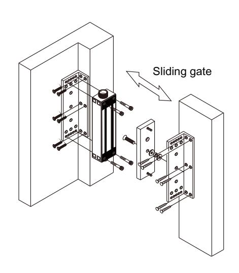
Attach the mounting plate to the jamb with the inlcuded Philips screws. Then use the thru-bolts to tighten the magnet to the mounting plate.
(Sample drawing as 8712FT Series magnet & mounting plate assemblies)
To adjust the gap between the armature plate and the magnet, add or remove the washers, or tighten the armature plate.
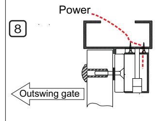
Connect the power and test the holding force. Add washers if there is still a gap between the magnet and armature plate.
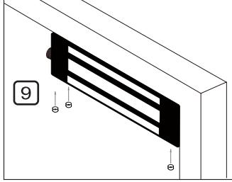
Insert the caps into the screw holes in the magnet.
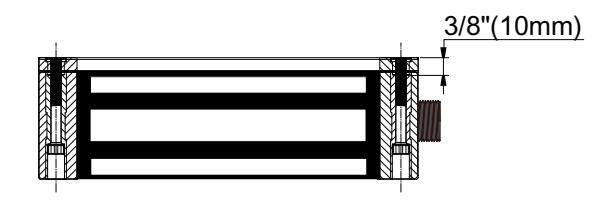
New Mounting Plate
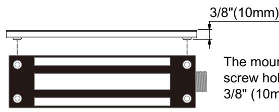
The mounting plate thickness at the screw hole at each end is increased to 3/8" (10mm).

Installation Instructions ROFU Gate Magnetic Locks with Conduit Fitting
8706FT and 8712FT Series (Face, Surface, and Sliding Gate Mount) *See page 5 for model specifications
ROFU Security International Corp. 10029 S. Tacoma Way, E-11 Lakewood, WA 98499 USA 1-800-255-7638 (1-800-ALL-ROFU) www.ROFU.com OrderEntry@ROFU.com

ROFU Z-bracket (#21031) Available for Inswing Gates (Face Mounting)
Note: Installation varies but intended for exterior usage, mounting holes thru the front of the magnetic lock.
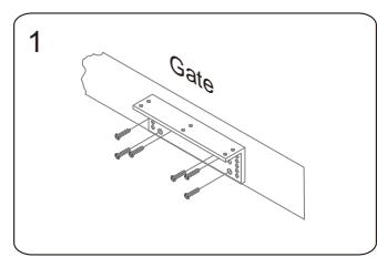
Find the correct mounting position on the gate for the L-bracket. Ensure that the gate still closes with it in position.
Use the thru-bolts to install the magnet onto the L-bracket.
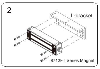
Assemble the Z-bracket, but not too tight as it needs to remain adjustable for now.
Insert the roll pins into the armature plate.
Attach the armature plate and washers to the Z-bracket assembly.
Close the gate and connect the power.
After the magnet engages the armature plate, you can now adjust the Z-bracket, and attach to the gate.
Ensure all screws of Z-bracket are tightening to gate. We encourage the use of thread locker (Loc Tite).
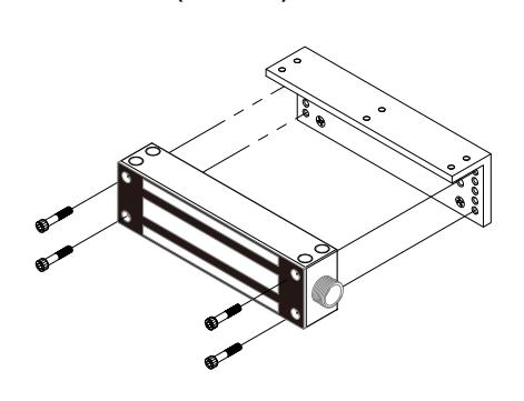
Magnet and Mounting Bracket (Face Mounting)
L-brackets for Sliding Gate Installation
8706FT Series (600lbs.)
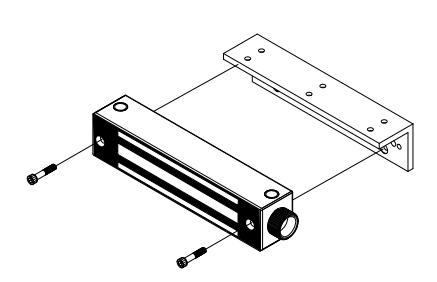
8712FT Series (1200lbs.)
8706FT Series (600lbs.)
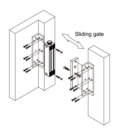
L-brackets for 8706FT Series are different from 8712FT Series. Please specify your request of brackets when you order.
8712FT Series (1200lbs.)
L-brackets (#21035) for 8712FT Series: Comes as a pair, to be used for armature plate and magnet (if needed) for gate installation.

Installation Instructions ROFU Gate Magnetic Locks with Conduit Fitting
8706FT and 8712FT Series (Face, Surface, and Sliding Gate Mount) *See page 5 for model specifications
ROFU Security International Corp. 10029 S. Tacoma Way, E-11 Lakewood, WA 98499 USA 1-800-255-7638 (1-800-ALL-ROFU) www.ROFU.com OrderEntry@ROFU.com

Installation Diagram & Screw Pack Components

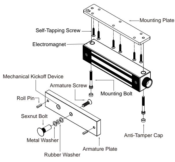
| 8712FT Series | |
|---|---|
| (1200lbs. Surface Mounting) | |
| Mounting Plate | |
| Self-Tapping Screw | |
| Electromagnet | |
| Mechanical Kickoff Device | |
| Roll Pin Mounting | Bolt |
| Sexnut Bolt Metal Washer | |
| Armature Plate | |
| Rubber Washer | Anti-Tamper Cap |
| Components | 8706FT Series | 8712FT Series |
| Blind Nut |
x 2
(1/4") |
x 3
(1/4") |
| Anti-Tamper Caps |
x 6
(13/32") |
x 12
(13/32") |
| Roll Pin |
x 2
(3/16" x 5/8") |
x 2
(3/16" x 5/8" ) x 2 (3/16" x 7/8") |
| Thru-Bolts (Hex Screws) |
x 2
(1/4" x 1 3/8") x 2 (1/4" x 1 9/16") |
x 4
(1/4" x 2") x 4 (1/4" x 1 3/16") |
| Rubber Washer |
x 2
(11/32" x 19/32" x 5/32") |
x 1
(11/32" x 19/32" x 5/32") |
| Philips Flat Head Screw |
x 6
(3/16" x 1 1/4") |
x 8
(3/16" x 1 1/4") |
| Allen Flat Head Screw |
X
(5/16" x |
1
: 1 3/8") |
| Metal Washer |
2
x 7/8") |
|
|
Hexagon Key
(Allen Wrench) |
x
(3/1 |
|
| Sexnut Bolt |
x
(1/2" x 1 |
|
| Blind Nut Assembly |
x
(1/4" x |
|
| Screw Nut | _ |
x 4
(1/2") |
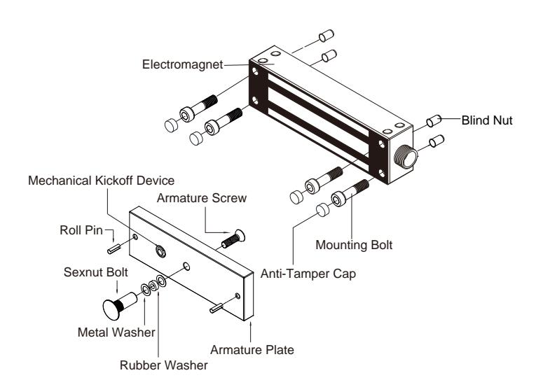
Note: No mounting plate is required for face mounting. Simply use blind nuts to install the magnet.
8706FT Series (600 lbs. Face Mounting)
Mechanical Kickoff Device Armature Screw Roll Pin Sexnut Bolt Anti-Tamper Cap Metal Washer Armature Plate
8712FT Series (1200 lbs. Face Mounting)
Installing Blind Nuts
Rubber Washer
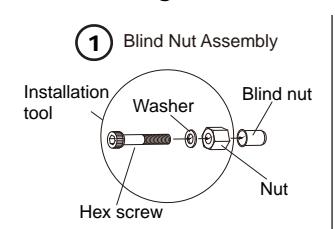
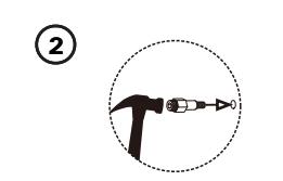
Drill a 3/8" (9.4mm) hole and hammer the blind nut assembly into the hole.
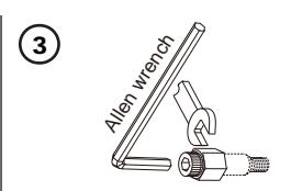
Use a wrench or vice-grip to tightly hold the nut. Then use the included Allen wrench to slowly tighten the screw until it does not turn any further.
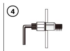
This compresses the blind nut so that it remains permanently fixed in the hole.

Remove the installation tool from the blind nut. Repeat step 2 through 4 for the other blind nuts.
Wiring Instructions
|
Wire Leads
(Polarity Insensitive) |
Power Input |
Bond Sensor
(Monitoring) |
Wiring Diagram | Models |
| 4 Wire Leads | 12/24 | None | 12VDC Operation Red White Black Green Access Control(s) 24VDC Operation Red White Power Supply Green Access Control(s) |
8706FT and
8712FT |
| 7 Wire Leads | VDC | ~ | 12VDC Operation Red White Black Green Access Control(s) Brown N.C. Blue COM. Yllow N.O. |
8706FT-B and
8712FT-B |

Installation Instructions ROFU Gate Magnetic Locks with Conduit Fitting
8706FT and 8712FT Series (Face, Surface, and Sliding Gate Mount) *See page 5 for model specifications
ROFU Security International Corp. 10029 S. Tacoma Way, E-11 Lakewood, WA 98499 USA 1-800-255-7638 (1-800-ALL-ROFU) www.ROFU.com OrderEntry@ROFU.com

Specifications
| Model |
8706FT
8706FT-B |
8712FT
8712FT-B |
|
|---|---|---|---|
| Holding Force |
600 lbs
1200lbs |
||
| Operating Voltage | 12/24VDC Selectable | ||
| Current Draw | 500mA/12VDC, 250mA/24VDC | ||
| Operating Temperature | 14°F~131°F (-10°C~55°C) | ||
| Magnet |
8"(L) x 1 11/16"(H) x 1 9/16"(W)
(203 x 43.5 x 40mm) |
8 11/16"(L) x 2 7/16"(H) x 1 9/16"(W)
(220 x 62 x 40.5mm) |
|
| Dimensions |
Armature
Plate |
7 1/4"(L) x 1 3/4"(H) x 9/16"(W)
(185 x 45 x 14mm) |
7 1/4"(L) x 2 3/8"(H) x 5/8"(W)
(185 x 61 x 16mm) |
| Conduit | 1" (25mm) outside, 3/4" (19mm) threads inside | ||
| Installation | Face, surface, and sliding gate mounting | ||
|
Finish
US32D Brushed Stainless Steel |
|||
Models Changes to ROFU Electromagnetic Locking Devices
Troubleshooting
| Problem | Possible Cause | Solution |
|---|---|---|
| Magnet does not lock | No power |
- Ensure all wires are connected properly.
- Check that the power supply is connected and works properly. - Ensure the REX is wired in Common and out the N/C position. |
| Low holding force |
Poor contact between magnet and
armature plate |
- Is the armature plate warped?
- Ensure the armature plate is loose enough to be able to "pivot" and bond with the magnet - Ensure the surface of the magnet and armature plate are clea-use a soft cloth and a spray lubricant to clean it. - Are you using rubber washer on end of through bolt? |
|
*Please remember to test
with the armature plate, not a screwdriver. |
Low voltage or incorrect voltage
setting |
- Check the mag lock and ensure it is set for correct voltage.
Check the voltage at the magnet input, if low-determine if you're using the correct gauge of double stranded wire. This will prevent excessive line (voltage) drop. |
|
Sensor output is
not functioning |
A second diode was installed
across the electromagnetic lock |
- Remove any diode installed across the magnet for "spike"
suppression. (The magnet has a metal oxide varistor to prevent back EMF) |