ROFU 8512-DE Delayed Egress Magnetic Lock Installation Instructions
Open the original PDF document
View PDF

ROFU Security International Corp. 10029 S. Tacoma Way, E-11 Lakewood, WA 98499 USA 1-800-255-7638 (1-800-ALL-ROFU) www.ROFU.com OrderEntry@rofu.com
Overview
The ROFU 8512-DE Delayed Egress Magnetic Lock Assembly is designed to comply with the NFPA 101 Life Safety Code. This delayed egress locking system's principal application is for secure locking and delayed release of perimeter and emergency exit doors. The ROFU 8512-DE electromagnetic lock is a self-contained, standalone unit that uses existing door exit and latching hardware, and all electronics are built into the magnet's wiring compartment for ease of installation.
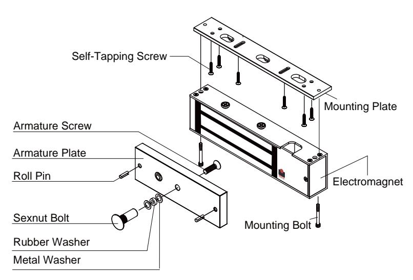
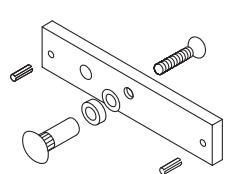
Screw Package Components:
| Roll Pin | Hexagon Key (Allen Wrench) | Rubber Washer | |||
| 3/16" x 5/8" | x 2 | 3/16" | x 1 | 11/32" x 19/32" x 5/32" | x 1 |
| Allen Flat Head Screw | Philips Flat Head Screw | Thru-Bolt (Hex Screw) | |||
| 5/16"x 1 3/8" | x 1 | 3/16" x 1 1/4" | x 6 | 1/4" x 1 9/16" | x 2 |
| Metal Washer | Sexnut Bolt | ||||
| 5/16" x 7/8" | x 3 | 1/2" x 1 9/16" | x 1 | ||
How it Works
The delayed egress system is activated by pushing on the exit push bar. The exit attempt (pushing on the exit bar) must exceed a pre-set nuisance delay of 0, 1, 2 or 3 seconds to start the delayed egress cycle. Note: the 0 second nuisance includes a 200 millisecond de-bounce delay to eliminate false triggering.
When the nuisance time is exceeded after applying a continuous pressure of 15 pounds or greater to the exit bar, an irreversible 15 or 30 second egress cycle begins. During this egress cycle, a piezo alarm beeps once for each second of the count-down. When the magnetic lock de-energizes to release the door for free egress after the delayed egress cycle, the piezo alarm sounds continuously and the door remains unlocked until reset.
Bench Testing
This procedure allows the installer to perform a quick bench check of the ROFU 8512-DE lock and to become familiar with the lock's basic operation prior to installation.
Test Set-up
Remove the cover plate and locate the 4-position DIP-switch on the bottom circuit board. Set all 4 switches to OFF. The lock is now set for zero seconds nuisance delay time and is set for 15 seconds delayed egress cycle. Proceed to wire the magnetic lock as follows:
1. In the lock's wiring compartment, locate the input terminal block on the circuit board and temporarily place a jumper across "FIRE" and "COM". Note: the two "COM" terminals are both common and either can be used for wiring convenience.

ROFU Security International Corp. 10029 S. Tacoma Way, E-11 Lakewood, WA 98499 USA 1-800-255-7638 (1-800-ALL-ROFU) www.ROFU.com OrderEntry@rofu.com
- 2. Ensure that the 12 VDC power supply is off and connect the positive (+) lead to terminal "+12" and negative to either "COM" terminal.
- 3. Connect a normally open single pole momentary switch to the "BAR" and "COM" terminals in the lock's wiring compartment. This simulated the exit bar's micro switch.
Note: Make sure the power supply is still off; place the armature (strike) plate on the magnet face and ensure that the plate is aligned properly.
Start-up Test
Turn on (or plug in) the power. The lock should beep once on power-up. The green LED should blink once per second. If any alarm sounds, the lock may be defective or the wiring is incorrect.
Reset Test
Two reset methods can be used:
- 1. Connect a normally closed switch in series with the power supply and the lock's "+12V" input terminal. Momentarily opening the switch will provide a reset.
- 2. Place a normally open switch across "RST" and "COM" terminals. Momentarily closing the switch will provide a reset.
Egress Test
- 1. Momentarily depress the exit bar switch (at least 200 msec and then release) to simulate an egress attempt. The sounder will start beeping once per second and the blinking LED will change to solid green to indicate an egress cycle has been initiated.
- 2. After 15 beeps the magnet will release the armature plate. The LED will change to solid red and the sounder will give a continuous alarm to indicate that the egress cycle is complete and that the lock will remain in the free egress alarm state until it is reset.
- 3. Momentarily activate the reset switch. The sounder will beep, the magnet will energize and the green LED will return to blinking once per second, indicating normal armed operation.
Fire Emergency Test
- 1. To simulate a fire emergency, remove the jumper you installed in Test Set-up between the "FIRE" and "COM" terminals. The lock will release immediately and will sound an on-off 2 per second pattern.
- 2. Remove DC power and temporarily reconnect the "FIRE" and "COM" jumper.
Bond Test
- 1. Place a business card at each end of the magnet between armature plate and magnet.
- 2. Apply DC power. After a 3 second delay, the bond alarm will sound a repeating pattern of 4 quick beeps, synchronous with the flashing LED.
When all the testing is complete, remove all wiring connections to the lock's terminals. Ensure that the jumper across "FIRE" and "COM" is removed.

ROFU Security International Corp. 10029 S. Tacoma Way, E-11 Lakewood, WA 98499 USA 1-800-255-7638 (1-800-ALL-ROFU) www.ROFU.com OrderEntry@rofu.com
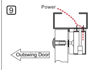
Magnetic Lock Installation for Outswing Doors
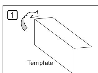
Find the paper installation template included with the magnet (you will need this).
Fold it on the dotted line.
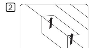
Place the folded template in the proper position on the door/jamb and mark the holes you will cut for your magnet and armature plate. (Using tape will help)
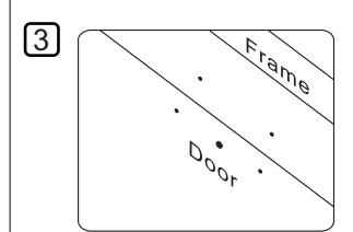
Drill the holes according to the marks you made.
(Check Twice! Drill Once!)..
4
Armature Plate Install the armature plate as shown in the drawing to the left.
The actual dimensions of the holes are illustrated below.
Hollow Metal Door Solid Door
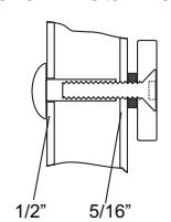
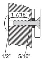
Drill a 5/16" (8mm) hole through the door for the armature side. For the sexnut side (secure side), enlarge the hole to
1/2" (12.7mm) for the width of the sexnut.
On wood doors the depth of the sexnut is 1 7/16" (36mm).

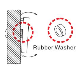
The rubber washer helps the armature plate to pivot. As it should NOT be tightened all the way to door.
6
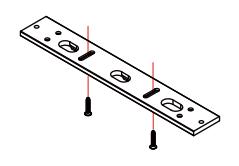
Attach the mounting plate to the jamb and tighten the mounting screws.
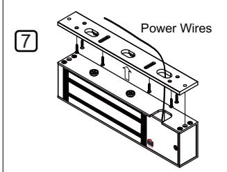
Pass the wiring through the mounting plate and into the wiring hole at the top of the magnet and into the PCB area.
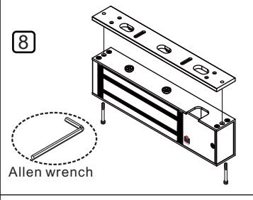
Attach the magnet to the mounting plate. Use the Allen wrench and thru-bolts to tighten the magnet to the mounting plate.
Connect the power and test the holding force. Add washers if there is still a gap between the magnet and armature plate.
Attaching Magnet to Mounting Plate
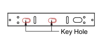
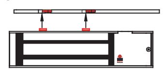
1. Align the two slotted holes and attach the magnet to the mounting plate.
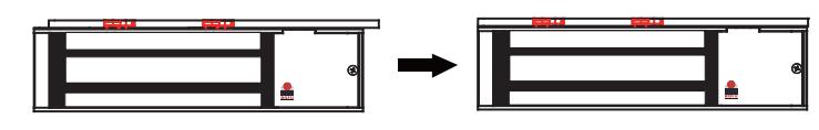
2. Slide the magnet onto the mounting plate.
Keyhole Mounting "slides Left to Right"

ROFU Security International Corp. 10029 S. Tacoma Way, E-11 Lakewood, WA 98499 USA 1-800-255-7638 (1-800-ALL-ROFU) www.ROFU.com OrderEntry@rofu.com
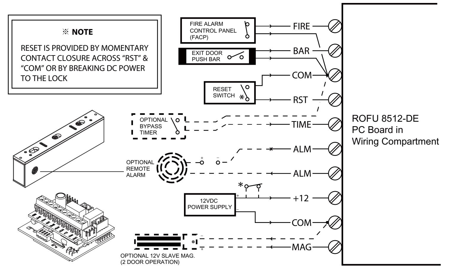
Wiring the 8512-DE Delayed Egress Magnetic Lock
Single Door Installation
- 1. All wiring must be fed through the ½" access hole previously drilled into the header.
- 2. The magnet is a low voltage device (NEC class 2) and can be powered by a 12 Volt DC power supply rated at 1.0 amps or greater. Use 18 AWG gauge wire. The power wire run should not exceed 75 feet. Observe polarity and connect the DC power supply to the "+12" and "COM" terminals.
- 3. Directly connect two leads from the normally closed dry contacts in the supervised Fire Alarm Control Panel (FACP) or other fire emergency system to the "FIRE" and "COM" terminals. Wire runs should not excced 1,500 feet. Use a minimum of 18 AWG gauge wire.
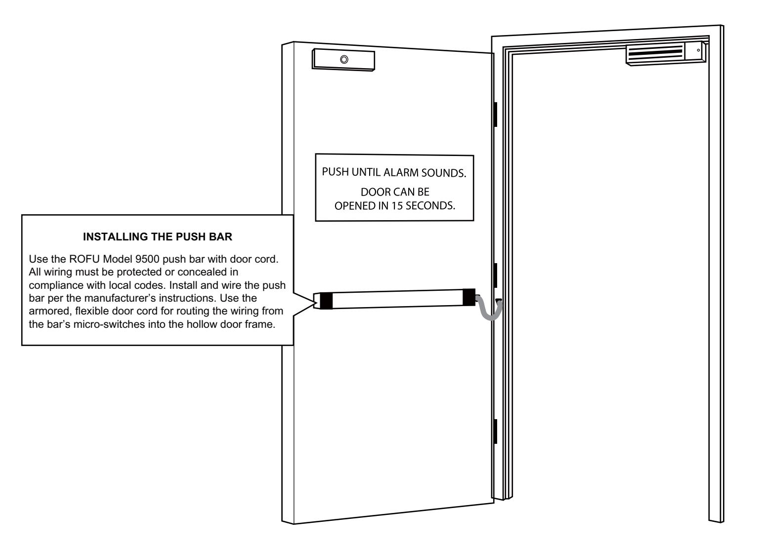
- 4. Directly connect the WHITE wire from the push bar to the "BAR" terminal and the BLACK wire from the push bar to the "COM" terminal.
- 5. Reset of the system can be done in two ways:
- A. connect a normally closed Form A contact switching device in series with the plus 12 volt DC power connection to terminal "+12"
- B. connect a normally open Form A contact switching device to terminals "RST" and"COM". Actuation of the momentary switch will result in a reset.
Connecting Optional Control and Remote Monitoring Devices
- 1. Form A dry relay contacts are provided for remote monitoring of the locking status. Whenever an alarm signal occurs due to a bonding violation, egress cycle or fire emergency, the output relay contacts across "ALM" and "ALM" will close. Contacts are rated 2 amps at 30 VDC.
- 2. A remote timer or momentary switch with normally open contacts can be installed to provide a manually controlled bypass for free egress. A contact closure across "TIME" and "COM" will release the lock for the duration of the maintained closure. During bypass, the LED will switch to red and will return to green when bypass is complete. The lock will also beep when the bypass is completed.
- 3. For 2-door (double door) operation, install a ROFU model 8512-LC lock on the adjacent door and connect it to terminals "MAG" and "COM". This slave lock will follow the operation of the master lock.

ROFU Security International Corp. 10029 S. Tacoma Way, E-11 Lakewood, WA 98499 USA 1-800-255-7638 (1-800-ALL-ROFU) www.ROFU.com OrderEntry@rofu.com
| Operational Features | |||
|---|---|---|---|
| 12 VDC input |
Current draw is approximately 0.5 amps and requires a 12 Volt DC power supply rated at 1 amp or
greater. CAUTION: This locking system is designed for 12 VDC +/- 10% |
||
| Selectable nuisance delay |
0, 1, 2 or 3 seconds. Exit bar must be pushed for the full duration of the preset nuisance time delay
to activate egress cycle. |
||
| Selectable egress delay time | 15 or 30 seconds | ||
| Reset method | Manually actuated electronic switch | ||
| Fire alarm connection |
Accepts normally closed contacts from a supervised Fire Alarm Control Panel (FACP).
The lock releases and sounds an on-off alarm pattern (2 per second) when fire contacts open. |
||
| LED status indicator |
Green LED blinks once per second during normal armed "door-secure" status.
LED turns to solid green during the egress count down and turns red when the magnet releases for free egress. Four repeating quick LED flashes indicate low bonding power. |
||
| Bond detection |
Four quick beeps indicate low bond conditions, including:
Low DC voltage Loss of bonding between the armature and the lock surface due to misalignment or mechanical restriction |
||
| Egress alarm sounder |
One beep per second during the egress cycle (15 or 30 beeps)
Continuous tone when the lock releases for egress |
||
| Alarm output contacts |
One 2 amp form. In an alarm condition the "ALM" output relay contacts close to activate remote alarm
signaling devices or alarm monitoring panels. |
||
| Watchdog circuit monitor |
This safety circuit constantly checks the lock's circuit board operation. A detected circuit malfunction
automatically releases the lock and sounds a continuous alarm. |
||
| Optional bypass |
The lock will be de-energized for the duration of a maintained bypass switch closure. Upon release of
the bypass switch, the sounder will beep and the lock will return to the normal armed and locked condition. |
||
| Optional "slave" magnet |
A 12 VDC output is provided to power a slave magnet for a two-door operation. CAUTION: Using a
slave magnet requires a larger power supply capable of supplying 1.5 amps at 12 VDC. |
||
Nuisance and Delayed Egress Cycle
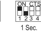
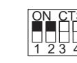
The ROFU 8512-DE lock can be set for nuisance delays of 0, 1, 2, or 3 seconds and for delayed egress cycles of 15 or 30 seconds via an internal DIP switch. Permission from the authority having jurisdiction is required for the 30- second egress cycle.
Nuisance Delay Settings Egress Delay Settings

0 Sec.
2 Sec.
1 2 3 4 ON CTS
3 Sec. 1 2 3 4 ON CTS
Dip Switch 1 & 2 Dip Switch 3
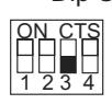
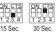
* Dip switch 4 has no function.
Electrical Ratings
| Power input | 12 Volt DC +- 10% |
|---|---|
|
Current draw
(Standalone operation) |
0.5 amps @ 12 VDC |
|
Current draw
(With optional slave lock) |
1 amp @ 12 VDC |
| Alarm output contacts |
2.0 amps @ 12 VDC
(maximum) |

ROFU Security International Corp. 10029 S. Tacoma Way, E-11 Lakewood, WA 98499 USA 1-800-255-7638 (1-800-ALL-ROFU) www.ROFU.com OrderEntry@rofu.com
Typical Delayed Egress Installation
Trouble Shooting
If the alarm sounds, note the sound pattern and troubleshoot as follows:
- a. One beep per second indicates that the push bar is activating the egress count down cycle. Check the bar's wiring and make sure the switch is wired for normally open operation.
- b. Steady on-off pattern (2 per second) indicates that the fire leads are not connected to the normally closed contacts in the FACP. Remove power and check wiring.
- c. Four quick beeps indicate a bond sensing violation. Causes can be low voltage to the lock or an improperly aligned armature plate or foreign matter between magnet and armature plate.