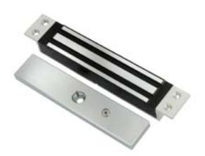
ROFU 8406M Sliding Door Magnet Installation Instructions
Open the original PDF document
View PDFROFU 8406M Sliding Door Magnet Installation Instructions This unit is 12/24VDC

Specifications
| Model | Holding Force | Current Draw | Optional Bracket |
|---|---|---|---|
| 8406M | 600 lbs(272 Kg) | 500mA/12VDC | #20925 |
| 0.00 | ( 3) | 250mA/24VDC | ,,,,,,,,,,,,,,,,,,,,,,,,,,,,,,,,,,,,,,, |
(This replaces the previous ROFU 8000)
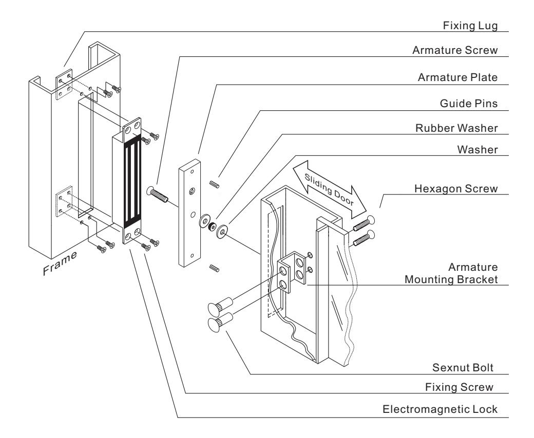
Installation Diagram
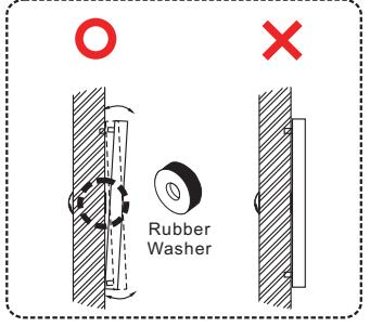
Thre rubber washer makes the armature plate float in order to reach proper combination with the magnetic lock.
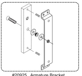
#20925 Armature Bracket (optional for ROFU 8406M)
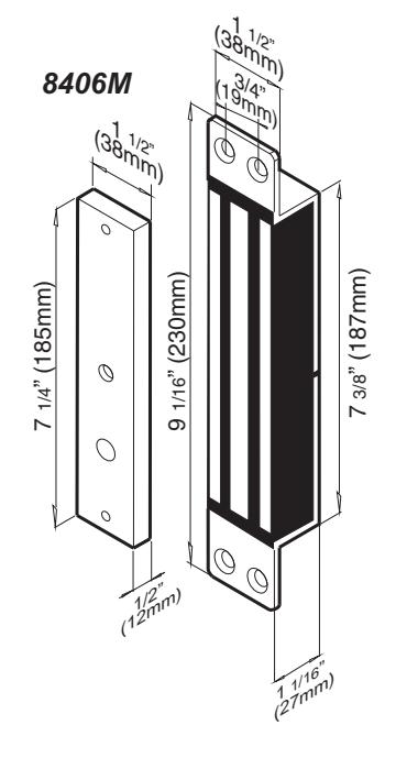
Dimensions

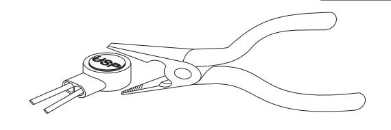
Use crimper or pliers and press the header of connector down to even position
Important Note
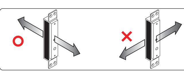
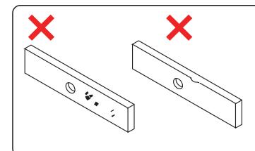
The 8406M requires a face-to-face alignment as shown in the far left figure. This magnet is NOT designed as a Shear Lock.
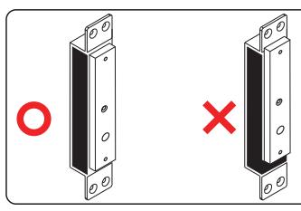
Ensure the surface area of the electromagnetic lock and the armature plate mate correctly or you will not get a good bond.
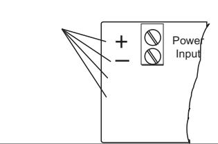
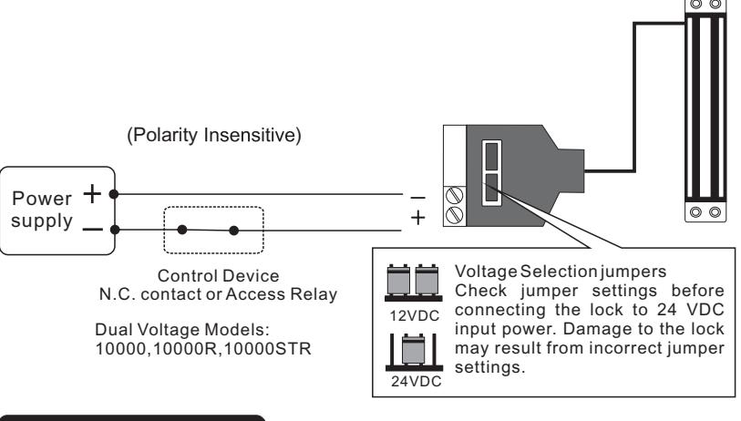
Ensure you notice the + and - although the unit is polarity insensitive.
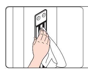
Ensure the face of the armature place and magnet are clean. Use a soft cloth to clean the surface. Never use anything abrasive to clean the magnet or armature plate.
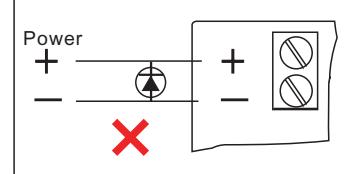
Remove any diode installed across the magnetic lock for spike suppression. The magnet is built-in with a metal oxide varistor to prevent back EMF.
Wipe the surface of magnet lock with anti-rust oil regularly.
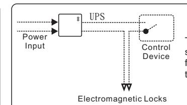
The electromagnetic locks are fail safe. Therefore it needs the power from UPS to remain locked during the power failure.
Trouble Shooting
| Problem | Possible Cause | Solution | |
|---|---|---|---|
| No power | Make sure the wires are connected properly | ||
| Door does not lock | Check that the power supply is connected and works properly | ||
| Make sure the lock switch is wired correctly | |||
| Poor contact between electromagnet and armature plate | Make sure the armature plate is not deformed | ||
| Make sure the rubber washer was used between the bracket and armature plate | |||
| Low holding force | Make sure the contact surfaces of the electromagnet and armature plate are clean and free from dust and foreign material. | ||
| Low voltage or incorrect voltage setting | Check the electromagnetic lock is set for the correct voltage. | ||
| Check the voltage at the electromagnetic lock input. If low, determine if the correct wire gauge is being used to prevent excessive voltage drop. | |||
| Sensor output is not functioning | A secondary diode was installed across the electromagnetic lock | Remove any diode installed across the magnet for "spike" suppression. (The magnet is fitted with a metal oxide varistor to prevent back EMF) | |
| Misalignment between the armature plate and electromagnetic lock | Make sure the armature plate and electromagnetic lock are aligned correctly | ||