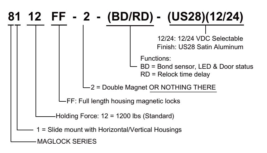
ROFU 8112FF Series Full Length MagLocks Installation Instructions
Open the original PDF document
View PDF

8112FF Series Magnetic Locks Installation Instructions for ROFU Full Length Housing Models
ROFU Security International Corp. 6818 S 220th ST Kent, WA 98032 (253) 922-1828 www.ROFU.com OrderEntry@ROFU.com
ROFU 8112FF Series FULL LENGTH LOCK HOUSING MODELS are equipped with a baseboard, and a security cover. Based on sizes of the doors, or the opening range, you may trim at your own discretion. These will enhance access control security and maintain the aesthetic appearance of the door as well.
Installations
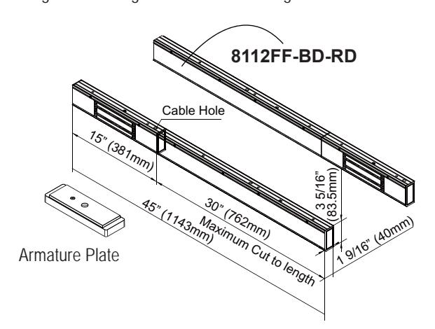
8112FF-BD-RD Installation
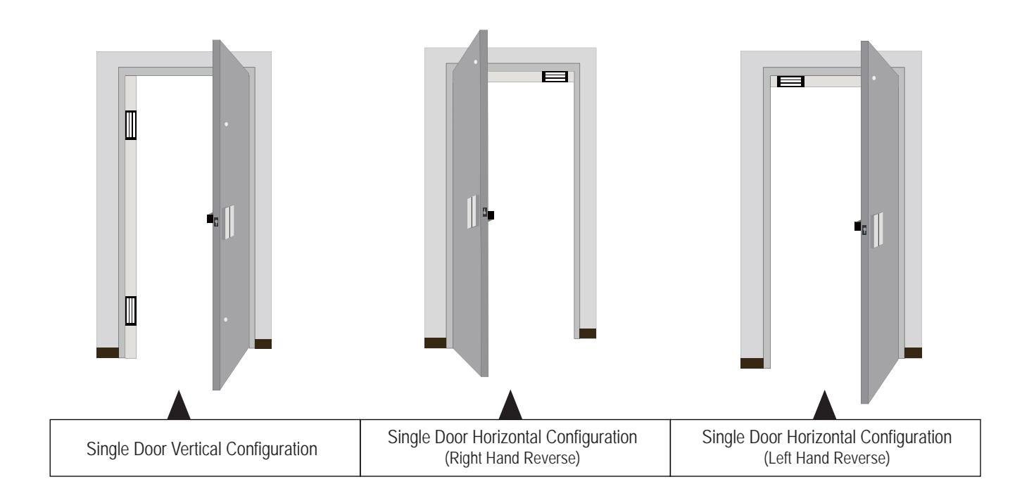
- 1. Make sure door opening direction and magnet location.
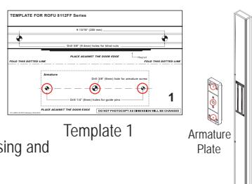
- 2. Fold the template on the dotted line to form a 90 degree angle. Place the folded template in the proper position on the door / jamb.
- 3. Drill 3/8" (9.4mm) cable access hole per the template (See instructions 4).
- 4. Drill the holes (See instructions 4 & 5) and install the armature plate per the template.
- 5. Place the magnetic lock directly against the armature plate and mark housing and mounting hole locations.
- 6. Remove the magnetic lock, drill marked holes and run the wires.
- 7. Install the magnetic lock with the provided screws.
- 8. Connect the PCB to the power and test the unit.
- 9. Complete installation.
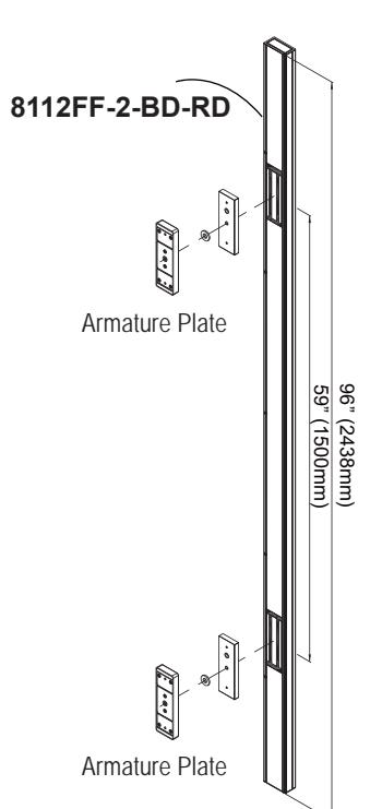
8112FF-2-BD-RD Installation
- 1. Use the tape to measure and mark the upper and lower magnet locations.
- 2. Fold the template 1 and 2 on the dotted line to form a 90 degree angle. Place the folded template in the proper position on the door /jamb.
- 3. Drill the holes and install the armature plates per the template (See Instructions 4 & 5).
- 4. Place the magnetic locks directly against the armature plates and mark the housing, cable access hole, and mounting hole locations.
- 5. Remove the magnetic lock, drill marked holes and run the wires.
- 6. Install the magnetic lock with the provided screws.
- 7. Connect the PCB to the power and test the unit.
- 8. Complete installation.
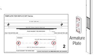
Template 2
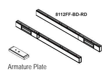
8112FF-2-BD-RD
1
Template 1
FOLD THIS DOTTED LINE FOLD THIS DOTTED LINE
TEMPLATE FOR ROFU 8112FF Series

Installation Instructions for ROFU Full Length Housing Models 8112FF Series Magnetic Locks
ROFU Security International Corp. 6818 S 220th ST Kent, WA 98032 (253) 922-1828 www.ROFU.com OrderEntry@ROFU.com
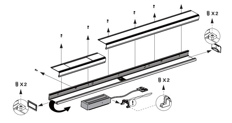
Instructions
- Unpack the 8112FF housing. Before disassembling, position the unit into its intended position to verify that it is the correct length/height for the door opening. For the dual Magnetic Lock model (8112FF-2-BD-RD), the magnet locations are equally spaced to each side of center of the housing as shown.
- 2. If the 8112FF-BD-RD housing exceeds the intended position, you may trim at your own discretion. Below please review all diagrams showing the recommended length.
3. For the 8112FF-2-BD-RD model, use the included blind nuts to stabilize the positions of the holes on the baseboard.
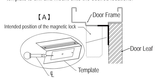
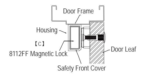
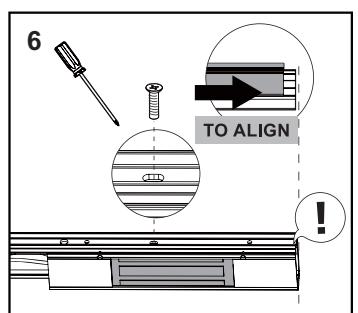
4. Diagram 【A】: Mark the median point between the magnetic lock and the door frame. Align alongside the armature plate and template to drill and mount onto the desired locations.
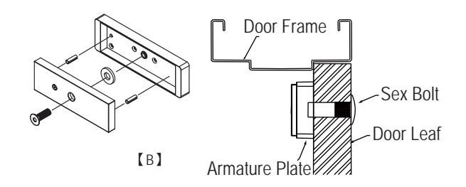
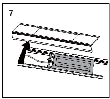
5. Diagram 【B】: Once the armature plates are correctly secured, install the cover and the baseboard tightly to the door frame. Mark the corresponding point of the permanent attachment hole, as well as the wiring hole to ensure the final fixation and the running of wires. See below diagram 【C】.
Screw Pack Components (Quantities shown are for the single magnet):
| (Qualitities shown are for the single magnet). | ||||||
|---|---|---|---|---|---|---|
|
Hexagon Key
3/16" |
x 1 |
Blind Nut Assembly
1/4" x 1 3/8" |
x 1 |
Blind Nut
1/4" |
x 4 | |
|
Roll Pin
3/16" x 5/8" |
x 2 |
Sexnut Bolt
1/2" x 1 9/16" |
x 1 |
Allen Flat Head
5/16" x 1 3/8" |
x 1 | |
| (E) Manual Maria | ||||||
|
Rubber Washer
9/16" x 1 3/16" x 5/32" |
x 1 |
Phillips Flat Head
3/16" x 1 1/4" |
х 6 |
Socket Head Cap
1/4" x 5/8" |
x 5 | |

Installation Instructions for ROFU Full Length Housing Models 8112FF Series Magnetic Locks
ROFU Security International Corp. 6818 S 220th ST Kent, WA 98032 (253) 922-1828
www.ROFU.com OrderEntry@ROFU.com
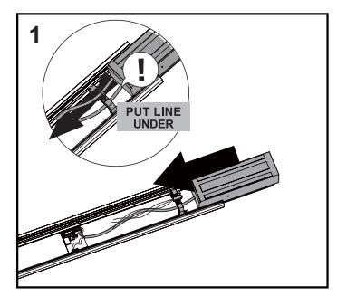
Installing Blind Nuts
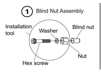
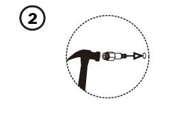
Drill a 3/8" (9.4mm) hole and hammer the blind nut assembly into the hole.
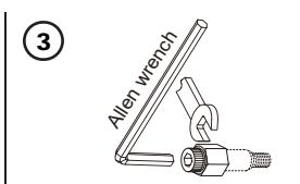
Use a wrench or vice-grip to tightly hold the nut. Then use the included Allen wrench to slowly tighten the screw until it does not turn any further.
This compresses the blind nut so that it remains permanently fixed in the hole.
Remove the installation tool from the blind nut. Repeat step 2 through 4 for the other blind nuts.
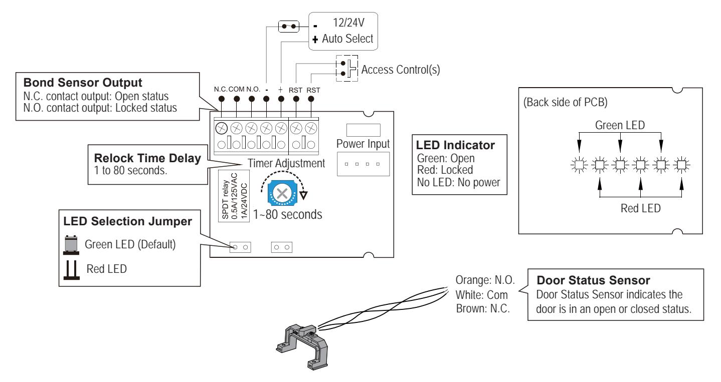
Wiring Diagram
Specifications:
| Model | 8112FF-BD-RD | 8112FF-2-BD-RD | |
|---|---|---|---|
| Voltage | 12/24VDC | 12/24VDC (each side) | |
| Current Draw |
500mA/12VDC,
250mA/24VDC |
500mA/12VDC,
250mA/24VDC (each side) |
|
|
Operating
Temperature |
-10~55 °C (14~131°F) | ||
| Holding Force | 1200 lbs | 1200 lbs (each side) | |
| Full Length | 45"(1143mm) | 96"(2438mm) | |
| Finish | US28 Satin Aluminum | ||
Model Changes to ROFU Electromagnetic Locking Devices

Installation Instructions for ROFU Full Length Housing Models 8112FF Series Magnetic Locks
ROFU Security International Corp. 6818 S 220th ST Kent, WA 98032 (253) 922-1828 www.ROFU.com OrderEntry@ROFU.com
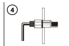
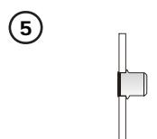
Reversing Magnet for Right or Left Handed Doors
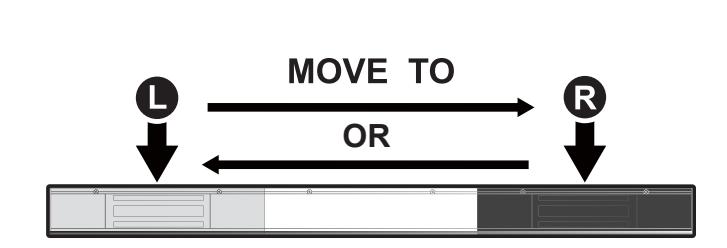
The PCB can be detached from the LED holder by pressing the buckles on both sides.
Place the reed switch between the magnet and the PC board. Slide the magnet into the housing.
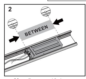
Move the magnet between the screw holes.
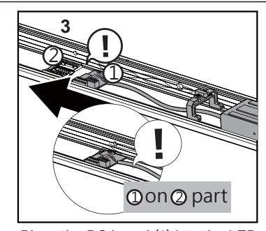
Place the PC board (1) into the LED holder (2).
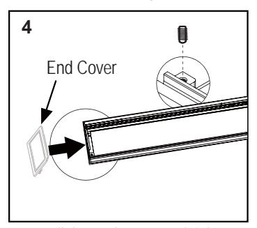
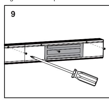
Install the end cover and tighten with M4 set screws.
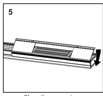
Close the magnet cover.
Slide the magnet and cover to the right end and tighten with Philips flat head screws.
Remove the magnet cover.
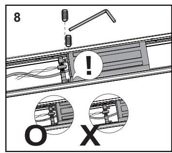
Place the reed switch under the magnet. O= The reed switch is tightly secured to the bottom of the magnet.
X= The reed switch is loosely attached.
Close the covers and tighten with Philips flat head screws. Same step from R to L side.