ROFU 8035 Shearlock Installation Instructions
Open the original PDF document
View PDFROFU 8035 SHEARLOCK INSTALLATION MANUAL

The 8035 series is available in two models, the 8035 is unmonitored or the 8035-002 has hall-effect monitoring. The units may be installed in wood, , metal or glass doors with or without available housings. This manual gives a guide to all of the above applications and other useful installation information.
ROFU Security International Corp. 6818 S 220th ST Kent, WA 98032 (253) 922-1828 www.ROFU.com OrderEntry@ROFU.com
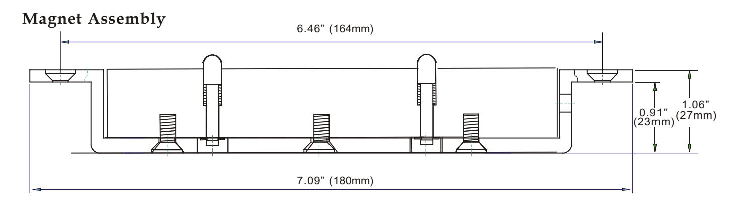
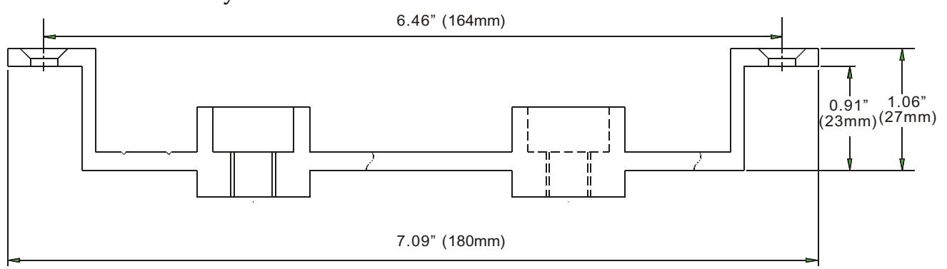
- 1. Full Dimensional Drawing
- 2. Technical Specification
- 3. Flush Installation
- 4. Semi-Flush Installation
- 5. Surface Installation
- 6. Full Glass Door Installation
ROFU 8035 Magnetic Lock Assembly
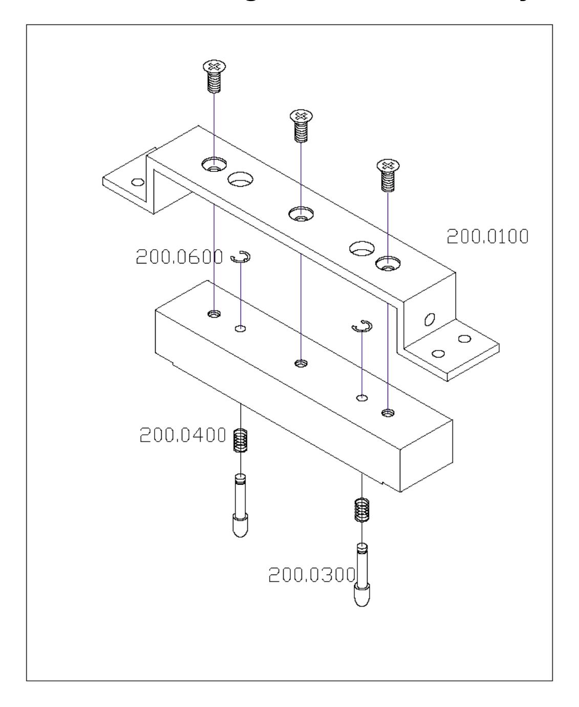
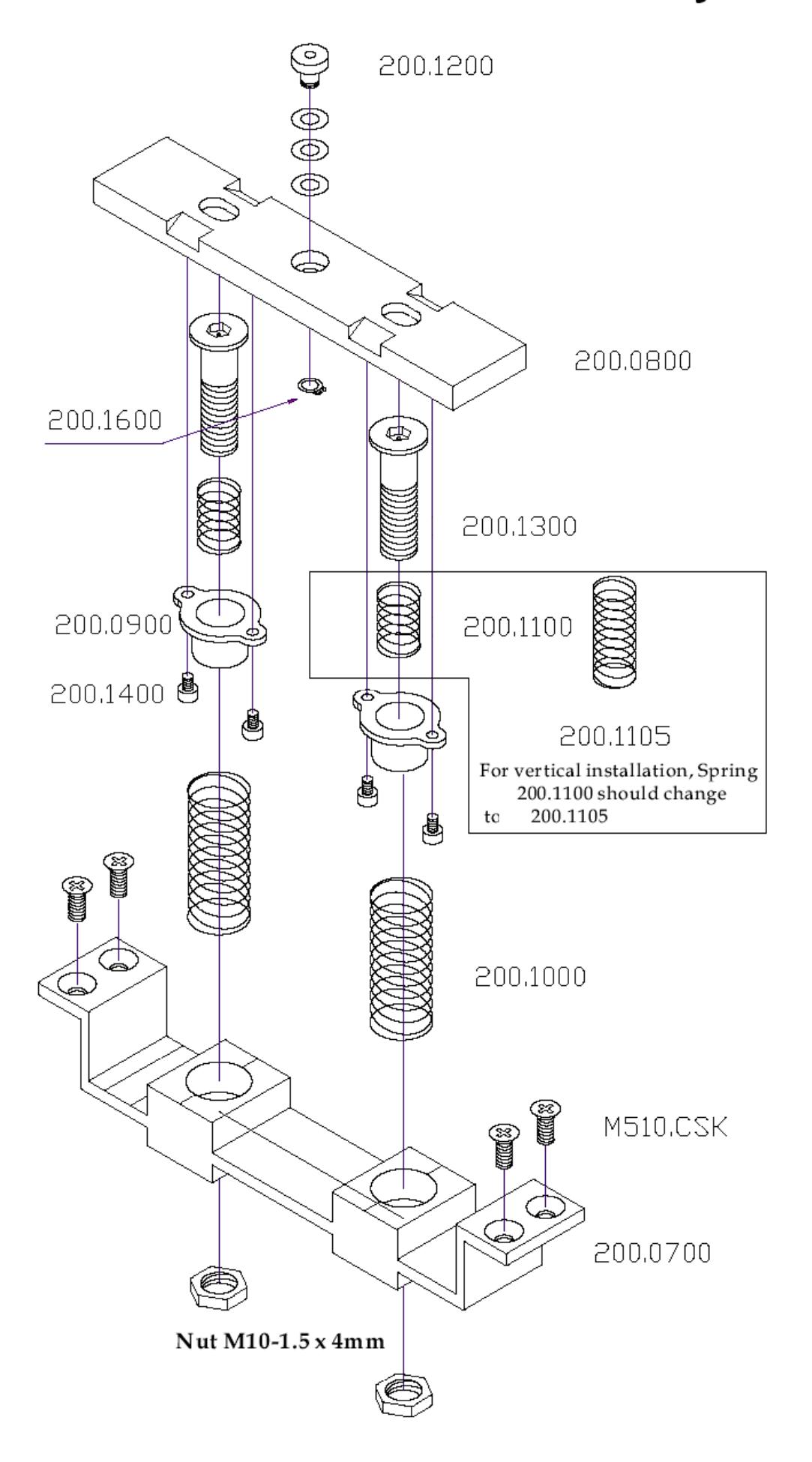
Full Dimension
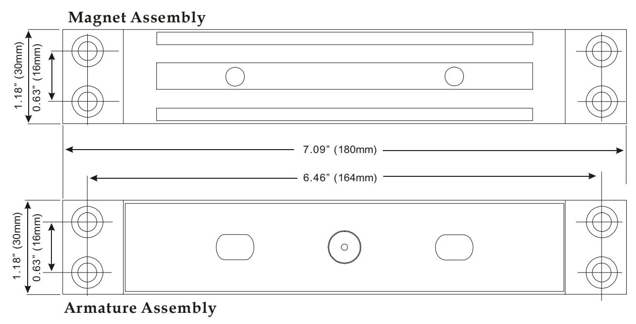
Side View
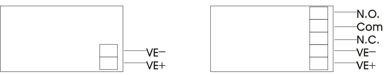
A rmature Assembly
TECHNICAL SPECIFICATION
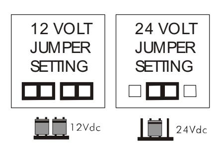
VOLTAGE 12VDC / 24VDC Selectable via jumpers
+ 10% over voltage is acceptable
Under voltage will reduce holding force
CURRENT CONSUMPTION 350mA @ 12VDC
190mA @ 24VDC
The unit does not require an initial voltage
Increase to operate.
DIMENSIONS 7 1/16" x 1 3/16" x 1 1/16" (180mm x 30mm x 27mm) Magnet
7 1/16" x 1 3/16" x 1 5/8" (180mm x 30mm x 42mm) Armature
7 3/16" x 1 7/16" x 1 7/8" (182mm x 36mm x 48mm) SMB200-HOUSING
OPERATING TEMPERATURE -30C to +50F
HOLDING FORCE: Up to 1500 lbs (680 kgs) in shear.
DYNAMIC STRENGTH FORCE: Up to 70 ft-lbs.
NOTE: THE LOCK SHOULD BE POWERED BY A LISTED UL603 / UL1023 POWER SUPPLY UNIT FOR USE WITH BURGLARY ALARM SYSTEMS.
|
Model
8035 |
Wire Gauge
0.01" (0.23 mm ) |
Number of Turns
420 Double Turns |
Maximum
Electric Resistant at 20℃ Ω ( ) |
|---|---|---|---|
| 25.3 |
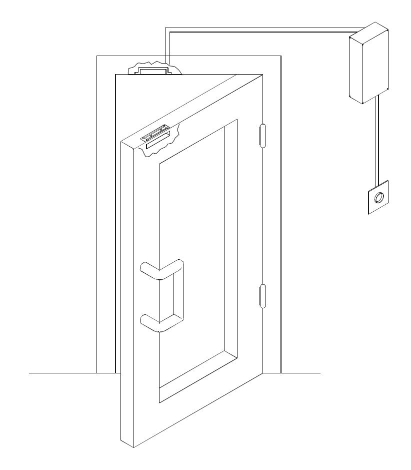
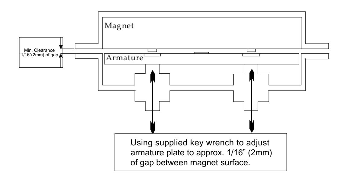
FLUSH INSTALLATION
The unit is designed to be flush mounted. The magnet should be fitted into the header (jamb) and the armature plate into the top of the door.
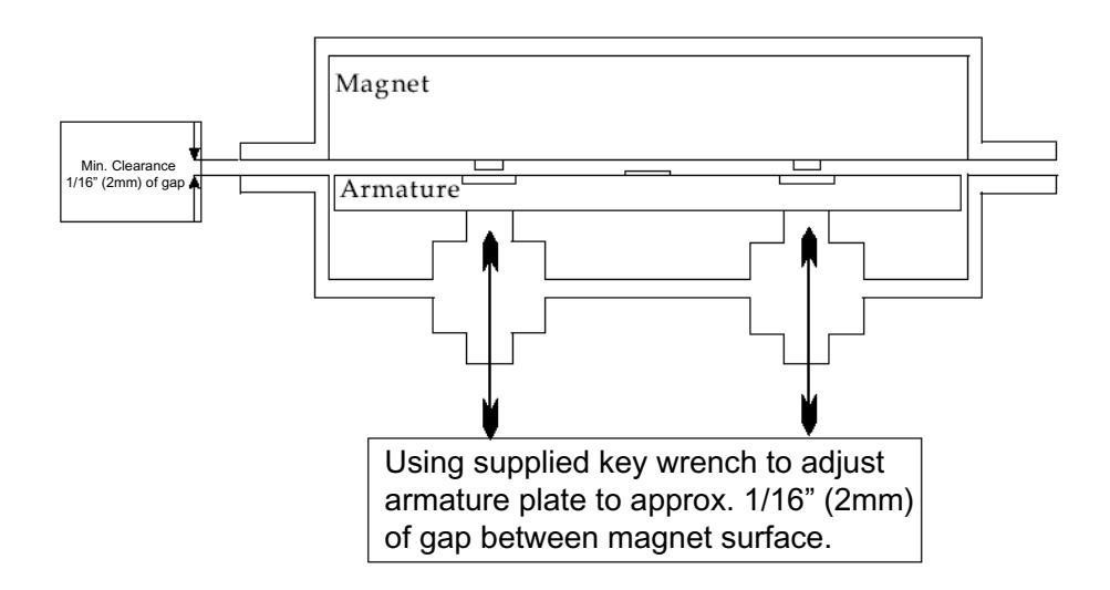
It is vital that a minimum gap of 1/16"(2mm) exists between the magnet and the armature, to allow correct operation.
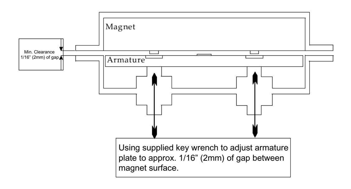
SEMI-FLUSH INSTALLATION
The unit may also be fitted semi-flush with the use of the 21036 housing. The magnet should be fitted to the door transom and the housing holding the armature on to the door.
It is vital that a minimum gap of 1/16" (2mm) exists between the magnet and the armature, to allow correct operation.
1/16" (2mm)
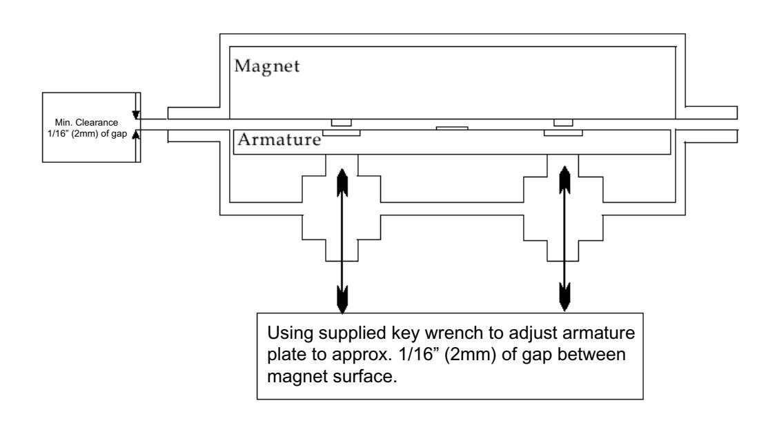
SURFACE INSTALLATION
The unit may also be fitted surface mounted using 2pcs of the 21036 or 21054 (Tamperproof) housing. The housing holding the magnet should be fitted above the door and the housing holding the armature on to the door.
It is vital that a minimum gap of 1/16" (2mm) exists between the magnet and the armature, to allow correct operation.
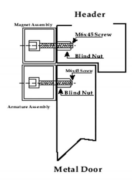
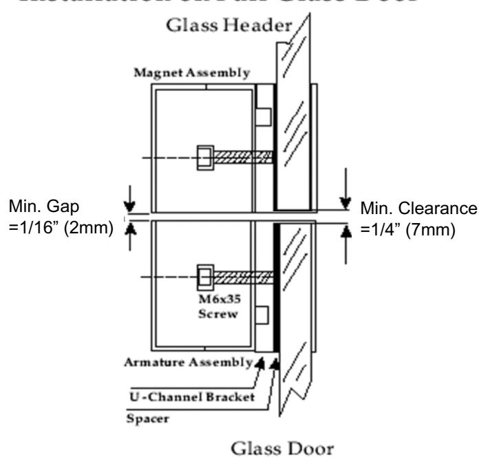
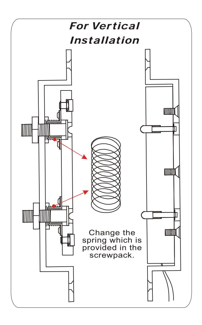
FULL GLASS DOOR INSTALLATION (NOT VERIFIED BY UL)
The unit may also be fitted to a full glass door and glass frame application, using 2pcs of the 21036 housing and 2pcs of the 21037 U-brackets. The housing holding the magnet should be clapped above the door and the housing holding the armature clapped on to the door. It is vital that a minimum gap of 1/16" (2mm) exists between the magnet and the armature, to allow correct operation.
NOTICE:
ROFU Security International Corp.
6818 S 220th ST Kent, WA 98032 (253) 922-1828 www.ROFU.com OrderEntry@ROFU.com