ROFU 8031-002 Shear Lock Installation Instructions
Open the original PDF document
View PDFROFU
ROFU 8031-002 Shear Lock Installation Instructions
ROFU Security International Corp. 6818 S 220th ST Kent, WA 98032 (253) 922-1828 www.ROFU.com OrderEntry@ROFU.com
Important Notes
Install the magnet assembly into the door frame before installation of the armature assembly into the door. The magnet assembly requires space to run wires, as well as space for the recessed portion of the unit. However, make sure that the position selected for the magnet assembly leaves enough room on the door to install the armature assembly.
Unbalanced air conditioning (stack pressure) can hinder door alignment and must be corrected to help ensure positive locking. It is important to note that the Shear Locks need a regulated 12VDC or 24VDC at the magnet. Use only the highest quality door closer. Positive centering door closers are required for all double acting door applications to help attain consistent dead center alignment. Also the door latching problems must be corrected prior to installation.
Specifications
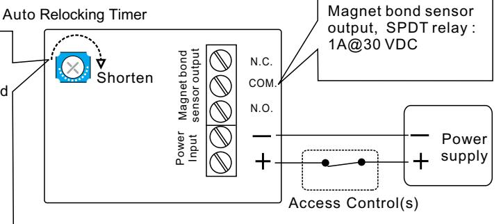
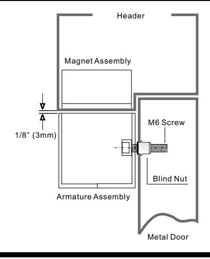
Holding Force Up to 2200 lbs in shear Power Input 12 to 24 VDC (self-regulating) Pull in:1.85A, Holding:0.45 AMP@12VDC Pull in:1.1A, Holding:0.25 AMP@24VDC Note: The unit does not require initial voltage increase to operate. Finish Magnet and Armature: Zinc plated Housing: Black powder coated Monitoring Output Magnet bond sensor output, SPDT rating 1 AMP@30 VDC Door Gap 1/8"(3mm) maximum Operating Temp. -22°F to +122°F (-30°C to +50°C) Auto Relocking Timer 1~6 seconds adjustable (Default: 3 seconds)
Connecting Diagram
The shear locks may be wired to one of two different electrical configurations. An auto locking time delay is recommended for all installations to delay relocking 1~6 seconds after initial door closure. This will help ensure the door is fully closed and at rest to obtain optimum alignment before the Shear Lock is energized.
Caution:
Make sure that the "+" and "-" wires are connected correctly. Failure to observe polarity will result in a short circuit and is not covered by warranty.
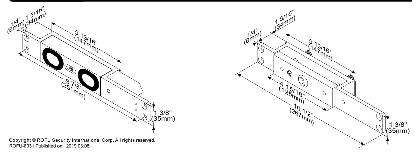
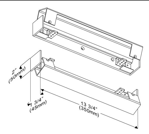
Dimensions
Flush Installation
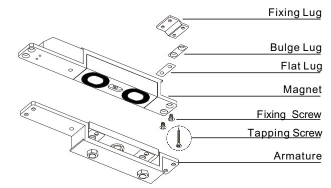
Bulge Lug is used when the magnet cannot be attached to the shallow door frame with fixing lugs and Philips flat head screws. When the situation happens, use the bulge lug to increase the frame thickness.

Flat Lug is used when the door frame is too thick, and to prevent the magnet or armature plate from caving in. Add flat lugs so that the magnet or armature plate is aligned to the door frame on the same level plane.
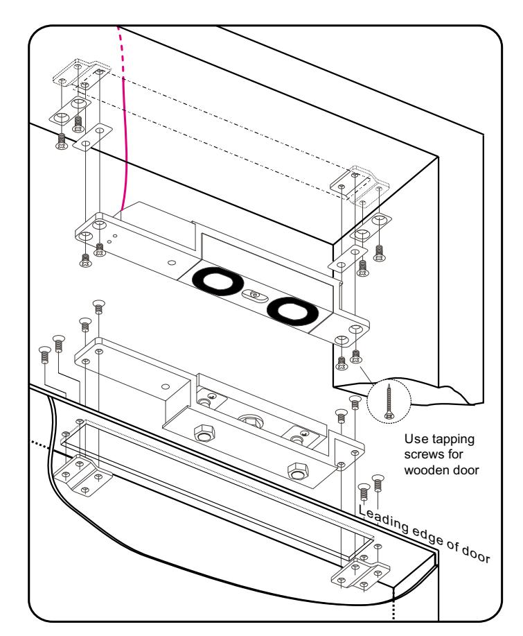
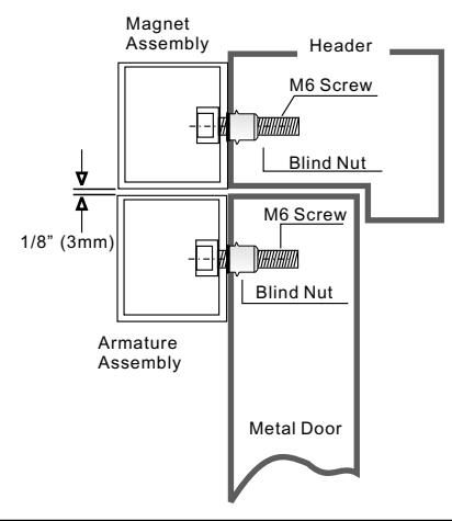
- 1. Make sure the gap between the door top rail and frame header is 1/8" (3mm). Make adjustments to the door as required.
- 2. Adjust single acting door and door closer to ensure the door settles immediately and is fully closed . (Adjust double acting door and POSITIVE CENTERING DOOR CLOSER to ensure the door settles immediately and is fully closed and at rest in the dead center of the frame.)
- 3. Determine the horizontal centerline of the door top rail thickness. The armature centerline will be the same. Mark the door per the template.
- 4. Before determining the header centerline, a single acting door must be fully closed. Double acting doors must be fully closed and at rest in the dead center of the frame. Mark the frame header per the template. Prepare the door and frame per the template.
- 5. When installing 8031-002, set the timer adjustment as required and test the locking time delay prior to mounting in the frame. The locking time delay is field adjustable for 1~6 seconds and is factory set at approximately 3 seconds.
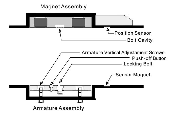
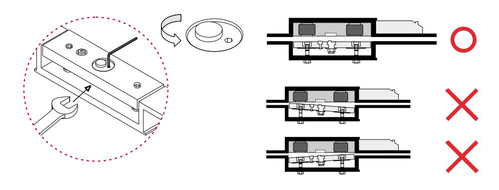
- 6. Install the magnet and armature with the auto relock switch assembly towards the leading edge of the door. For proper operation, the armature must be adjusted upward as close as possible and parallel to the magnet without interfering with opening and closing of the door. Proper operation cannot be expected with more than 1/8"(3 mm) gap between the armature and the magnet. Use the key wrench provided to adjust the armature vertical adjustment screws.
- 7. With the door closed, turn the lock power on. Check the lateral alignment. The armature locking bolt should be centered to the locking bolt cavity. Adjust the locking time delay to avoid early activation and help ensure positive locking on door closure. Adjust inward to delay shear lock activation. Don't adjust higher than the armature rest position.
- 8. Repeat steps 6 and 7 as necessary following shear lock replacement. Cycle the door and shear lock several times after the completion of installation.
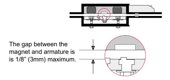
hcn re wyek Using supplied key wrench to adjust armature plate to approx. 1/8" (3mm) of gap between magnet and armature.
Identify the thickness of the door leaf or frame header and inspect to determine if 21059 bracket is required.
Semi- Flush Installation
The ROFU 8031-002 may also be fitted semi-flush with the use of the 21059 Bracket. The magnet should be fitted to the door transom and the housing houlding the armature on to the door. It is vital that a minimum gap of 1/8"(3mm) exists between the magnet and the armature, to allolw correct operation.
Surface Installation
The ROFU 8031-002 may also be fitted surface mounted using 2pcs of the 21059 Bracket. The housing holding the magnet should be fitted above the door and the housing holding the armature on to the door. It is vital that a minimum gap of 1/8" (3mm) exists between the magnet and the armature, to allow correct operation.
☐ Blind Nut Installation
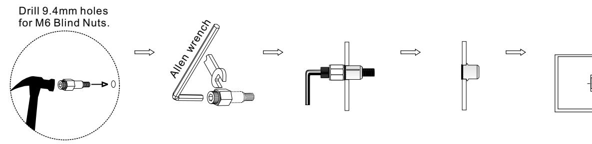
Insert two blind nuts into separate holes, one for each fixing screw.
Use the Allen wrench to slowly tighten the blind nut
This compress the blind nut so that it remains permanently fixed in the frame.
Remove the tool.
Use M6 screws to install the 21059 bracket.
M6 Screw
Blind Nut
Trouble Shooting
| Problems | Possible Cause | Solution | ||||
|---|---|---|---|---|---|---|
|
The gap between the armature and the magnet is
too large. |
Adjust the armature plate and arrange the gap between
the armature and the magnet within 1/8" (3mm). |
|||||
| Door does not lock | No power. |
Check power sypply if the unit is powered with the correct input
voltage and draws the specified current. |
||||
|
The door leaf does not return back at the correct
position. |
Positive centering door closers are required for all double acting
door applicators to help attain consistent dead center alignment. |
|||||
|
The gap between the armature and magnet is too
large. |
Adjust the armature plate and arrange the gap between
the armature and the magnet within 1/8"(3mm). |
|||||
|
The armature plate keeps
projecting the bolt into the |
Voltage too low. |
Check power sypply if the unit is powered with the correct input
voltage and draws the specified current. |
||||
| cavity. | The magnet is not parallel to the armature plate. |
Adjust the armature plate and make sure the magnet is parallel
to the armature plate. |
||||
|
The locking bolt does not correctly seat inside the
cavity of the magnet. |
Adjust the locking bolt of the armatue plate and make sure it
correctly seats inside the cavity of the magnet. |
|||||
| The armature plate is not in the | The position of the locking bolt is not correct. |
Adjust the locking bolt of the armature plate and make sure
it correctly seats inside the cavity of the magnet. |
||||
|
right position and the locking
bolt cannot seat correctly into the cavity of the magnet. |
The magnet is not parallel to the armature plate. |
Adjust the armature and make sure the magnet is parallel to the
armature plate. |
||||
|
The time setting for auto relocking time delay is too
short. |
Adjust auto relocking timer. | |||||
Use spanner and allen wrench to release the locking bolt on the armature plate. Rotate the position of the locking bolt in order to correctly seat inside the cavity of the magnet.
Make sure the magnet is parallel to the armature plate.
The current draw is large (1.8A @12VDC; 1A@24VDC), so make sure the wire is capable to handle long runs. It is also necessary to make sure the output current is sufficient for the required power.
Distance in feet from power source to farthest locking device
|
Minimum
Wire Gauge for 12 VDC |
|||||||
|
Minimum
Wire Gauge for 24 VDC |
|||||||
ROFU-8031 Published on: 2019.03.08