ROFU 3850 Series Electric Dropbolt and Electromechanical Lock Installation Instructions
Open the original PDF document
View PDF

3850 Electric Dropbolt Manual
Statement
The 3850 Electric Dropbolt is Aluminum housing designed for elegant appearance and enhanced durability. The 3850 Electric Dropbolts are available in 32mm and 38mm wide faceplates (same as common faceplate dimension) with DPS (Door Position Status) output.
Application
Frameless glass door, hollow metral door frame

Double Action Doors
3850 electric dorpbolt is especially designed for both out-swing and in-swing doors.
Vandal Resistant Circuitry Design
The reed sensor automatically disconnect once the bolt is completely locked to avoid unauthorized access attempts.
Long Life Solenoids
Specially designed solenoid for enhanced strengh and long operating life time through up to 500,000 cycle tests.
Energy Saving Design
After the electric dropbolt is completely locked, the current draw drops from 0.9A to 0.3A to prolong its lifetime.
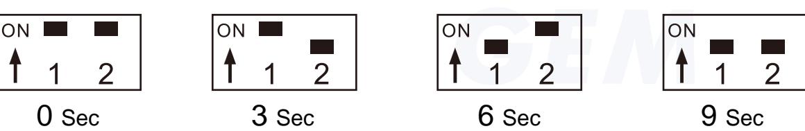
Relay Strike Time (Time Delay Setting)
Adjustable time delay of 0, 3, 6, 9 seconds (Default value is 0 second). Once the magnet is sensed by the dropbolt, the lock bolt will stick out after the time delay. The time delay is set to lock up the electric dropbolt after the closed door is completely still.
Specification
| Parameter | Description |
| Operating Voltage |
10%)
(Tolerance |
| Current Draw |
Pull in: 0.9A@12VDC
Holding: 0.3A@12VDC |
| Operating Temperature | -10~45°C |
| Relay Electric Current | 0.25A@30VDC |
| Relay Strike Time | 0, 3, 6, 9 seconds |
| Surface Temperature | Ambient Temperatur +20°C |
| Solenoid Test | Over 500,000 times |
| Faceplate Material | Alluminum Alloy |
| Weight | About 1~2 kgs |
Ordering Information
Ordering Code: 3850
Each standard package includes the following:
| Parts | |
|---|---|
| Electric Dropbolt | |
| Strike Plate | |
| Fixing Lug | 4 |
| Adjusting Washer | |
| Bracket | |
| Square Screw(4mm) | 4 |
| Pozi Pan Machine Screw (4x12mm) | |
| Pozi Pan Machine Screw (5x12mm) | 8 |
| Pozi Pan Self Tapping Screw (Pointed, 5x32mm) | |
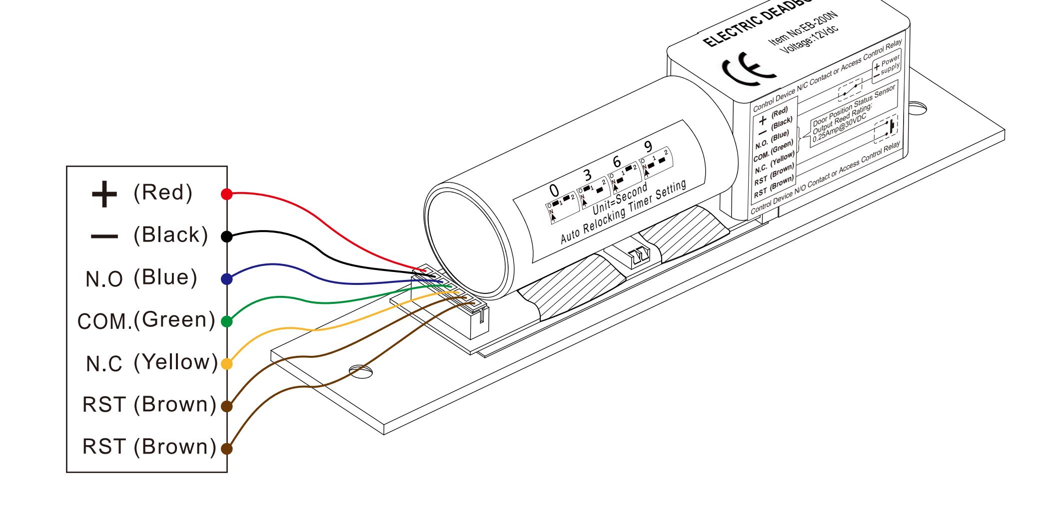
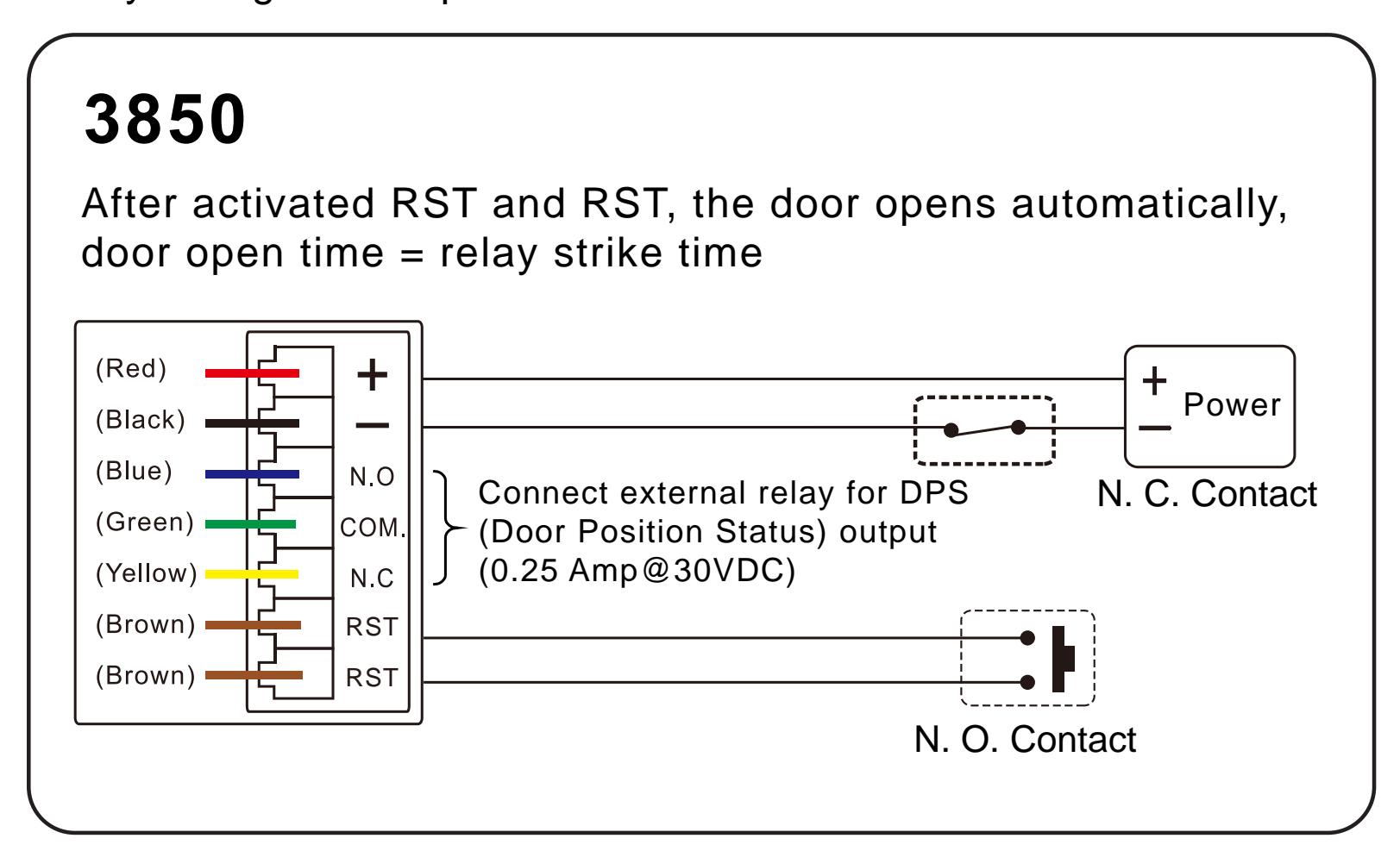
Wiring Diagram
Relay Strike Time
| Time | 1 | 2 |
|---|---|---|
| 0 sec. | ON | ON |
| 3 sec. | ON | OFF |
| 6 sec. | OFF | ON |
| 9 sec. | OFF | OFF |
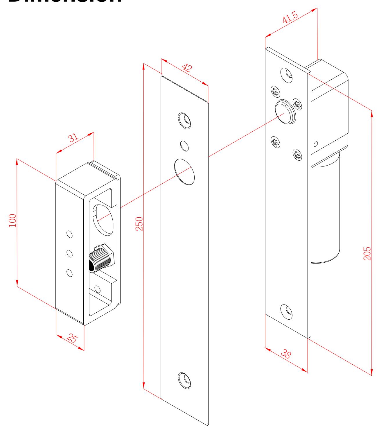
Dimension
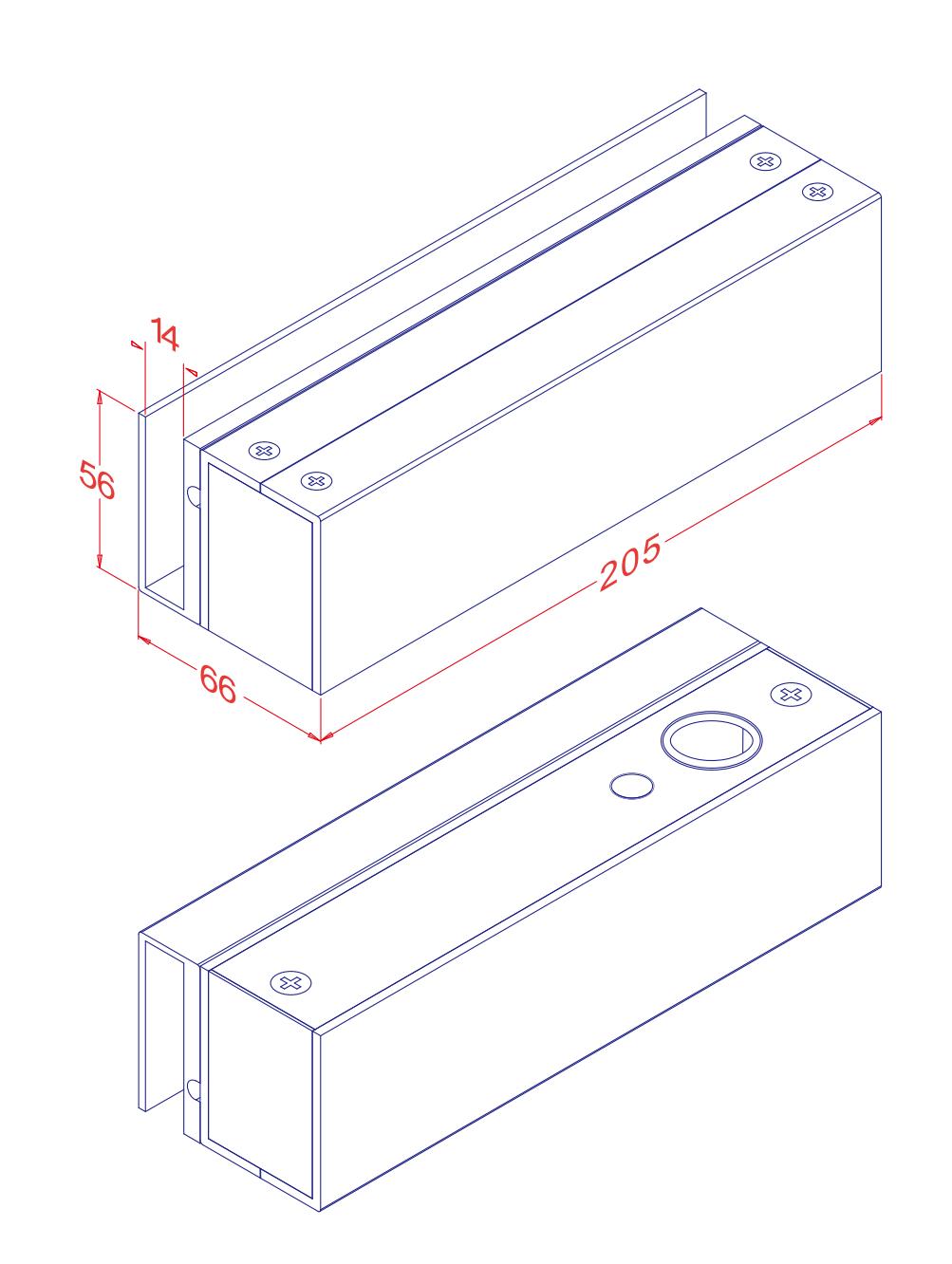
Optional Bracket
3850 can be mounted on frameless glass doors and glass walls.
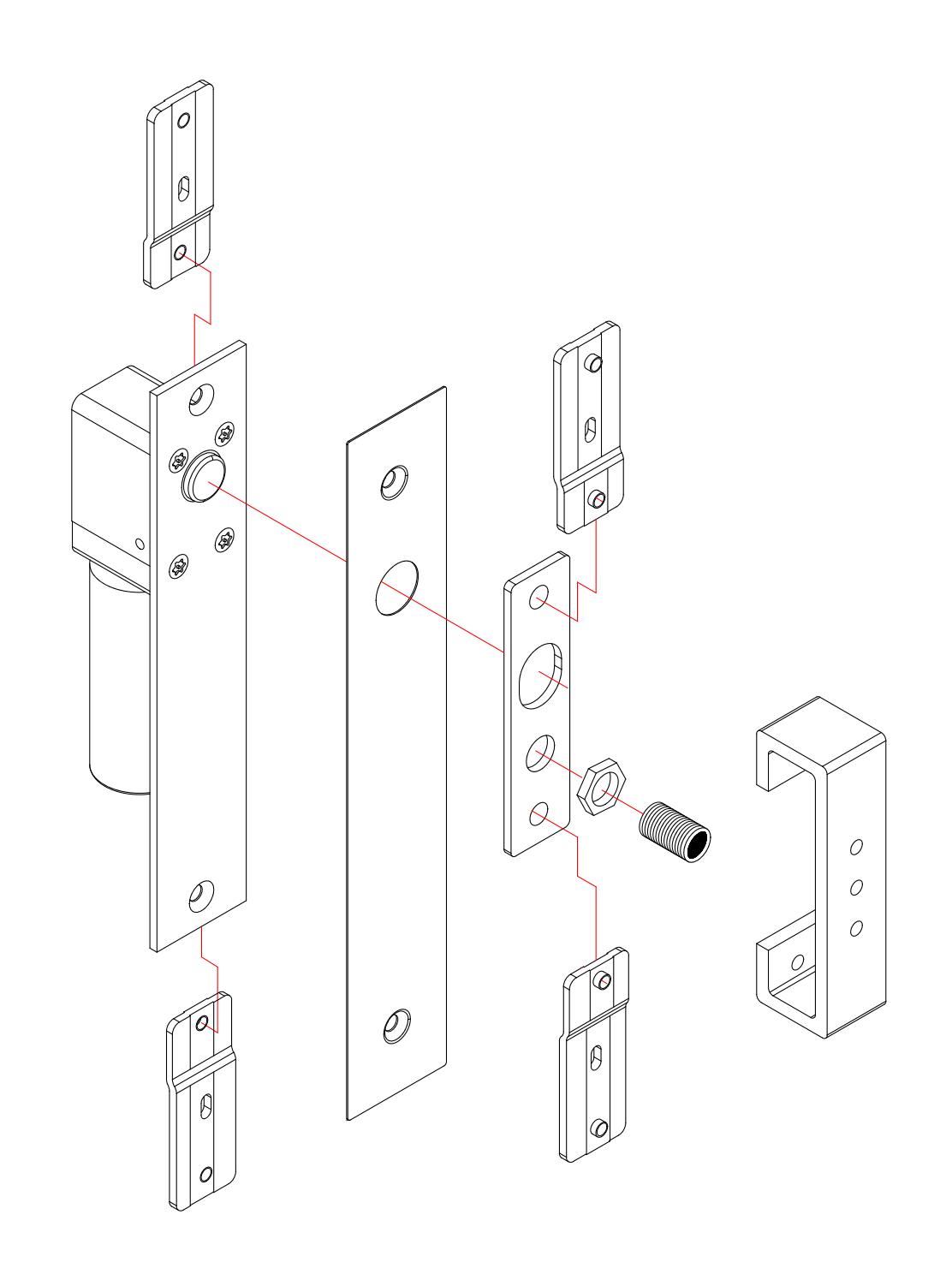
Installation Diagram
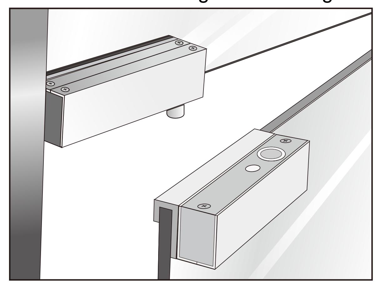
Suface Mount (Narrow Frame)
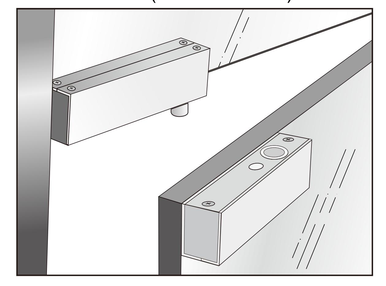
Mount on frameless glass doors / glass walls
Installation Instruction
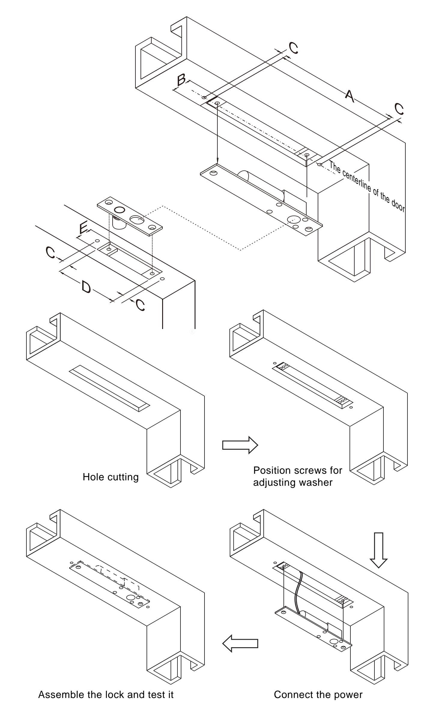
Mortise Mount Hollow Metal Door Frame
Please refer to the particular pattern template for each specific cutting size and the location to drill the screw holes.
| 3850 |
|---|
General Installation Instructions:
Ensure the width and depth of the door frame, door leaf (hollow metal door) are enough to install the lock body. Also check if it is possible to place the wires inside the door frame.Ensure the double action door swings back to correct position after use to make sure the electric dropbolt locks up quickly. Therefore the door hinge/ automatic door operator of the double action door is very important.
Check if the regulated power supply or controller can provide the current draw(pull in:0.9Amp@12VDC holding: 0.3Amp@12VDC) and that the voltage can be maintained during operation under all circumstances.
Installation Steps:
- 1.Test if the automatic door operator of the single swing door could completely close the door by a single swing. Check if the centerline of a double-swing door frame and door leaf is coincided.
- 2.Mark the center point position of the door frame and the door leaf.
- 3.Mount the supplied installation template for the electric dropbolt and strike plate to align them to the door and door frame's center point.
- 4.Ensure installation according to the template supplied. Mark the hole cutting and drilling position. Adjust the relay strike time (time delay setting). (Default setting is 1 second). Supply power, make sure all wirings are correct and tightened to secure the electric dropbolt and strike plate on the door and the door frame.
- 5. Close the door and check if the lock function works normally. If any of the below situations happens, please find out the causes and begin trouble shooting.
- A. Electric dropbolt is not working: Check if the wiring is correctly connected and if the magnet is out of sensor range.
- B. Re-check the previous steps: The latch bolt may be stuck inside the keeper hole or the power is not enough.
- 6. Note: NEVER lubricate the lock and the latch bolt with lubricating oil (grease). Please install the lock after the interior decoration is finished.
- 7. Please see page 4 for other trouble shooting details.
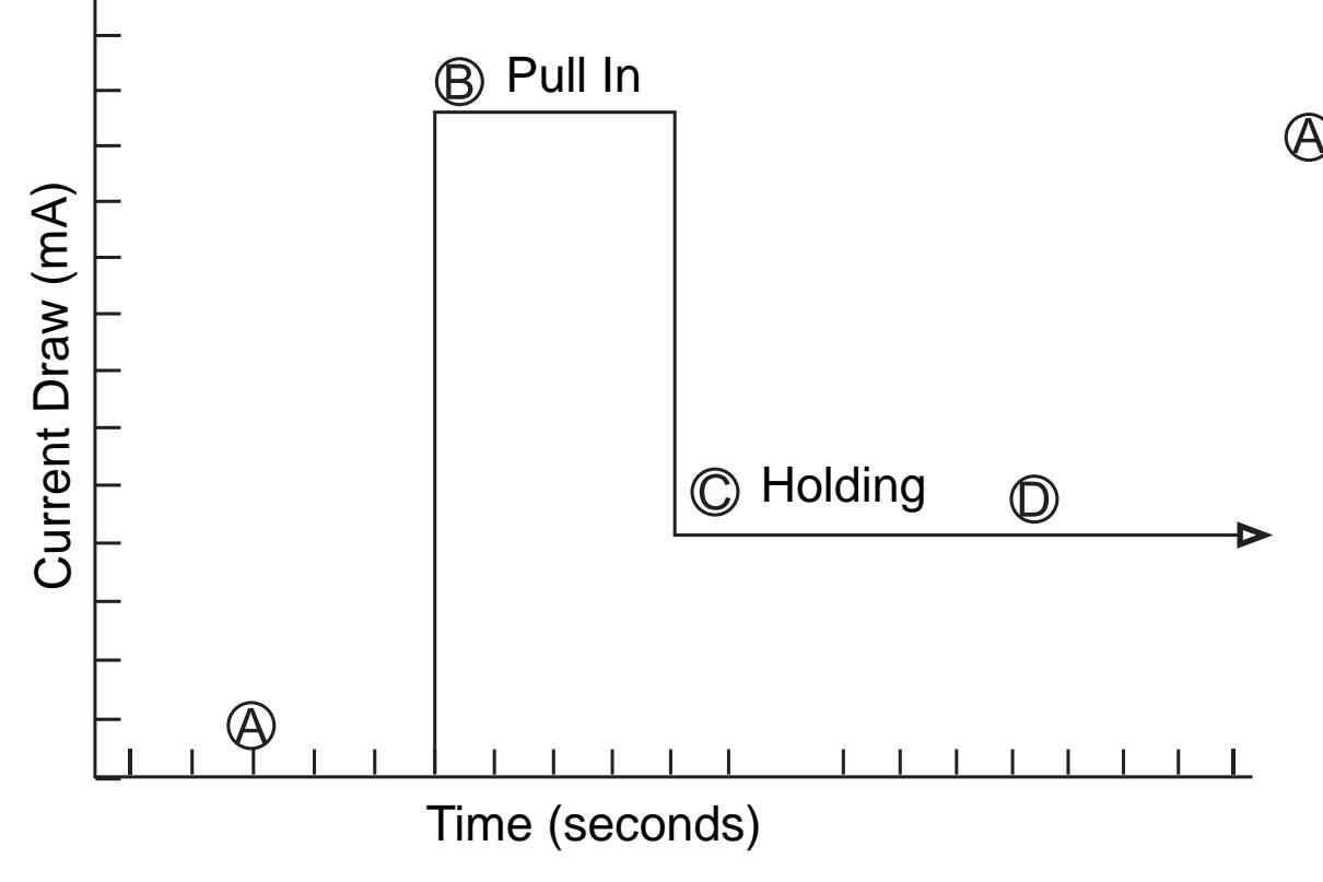
Energy Saving Design
-
Door close time: When the sensor magnet in the strike plate detects the reed in the lock body, the dropbolt projects at once. -
-
Under the energy saving design, after the dropbolt completely locked, the current draw will drop from high pull in current to low, continuing 'holding force'.
- The reed in the lock body will automatically switch off at the same time when the dropbolt is locked.
-
Under the energy saving design, after the dropbolt completely locked, the current draw will drop from high pull in current to low, continuing 'holding force'.
Wiring Diagram
Caution:
Make sure that the "+" and "-" wires are connected correctly. Failure to observe polarity will result in a short circuit and is not covered by product warrant.
Note: The relay rating is 3 Amp@30VDC. Please do not connect to external high voltage.

Trouble Shooting
| Problem | Possible Cause | Solution | ||
|---|---|---|---|---|
| Dropbolt does not activate when |
The gap between the strike plate and
the electric dropbolt lock is far. |
Adjust the distance between the reed in the lock body
and the sensor magnet in the strike plate within 5 mm. |
||
| the door closes. | No voltage or low in voltage. |
Make sure the output voltage and the current are
large enough to pull in 0.9A current draw. |
||
|
The dropbolt keeps the projecting
motion. |
The dropbolt is not locked properly. |
1. Adjust the door closer or the door hinge for the door
leaf to close in the correct position. |
||
|
2. If solution 1. cannot work, it is recommended to
change the double action door to single action door. |
||||
| The dropbolt cannot retract. |
1. Release or sway the door to release the latch bolt
to open the door. |
|||
| Strike plate misaligned. |
2. If solution 1. cannot work, it is recommended to
change the double action door to single action door. |
|||