ROFU 3820 Series Motorized Cabinet Lock Instructions
Open the original PDF document
View PDF

ROFU 3820 Motorized Cabinet Lock Instructions
ROFU Security International Corp. 6818 S 220th ST Kent, WA 98032 (253) 922-1828 www.ROFU.com OrderEntry@ROFU.com
The ROFU 3820 Motorized Cabinet Lock is designed for fail secure operation. It includes a bond sensor and door status output to monitor if the cabinet is locked/unlocked and closed/open. We also added a spring feature on the post mount so that the door will actually "spring" away when the lock releases to gently push the door open. It can be installed into closets, lockers, filing cabinets and drawers. The 3820 provides a full voltage range of 12 to 28 VAC/VDC with minimal current draw.
Features
- Surface-mounted compact electric lock
- Motor operated
- Field adjustable relock time delay (2 or 5 seconds)
- Stainless steel locking pin assembly
- Low energy consumption
- Lock or door status monitor
- Versatile mounting positions
Applications
- Gym lockers
- Filing cabinets
- Cash drawers
- Drug cabinets
- Showcases
- Vending machines
Specifications
| 12 to 28 VAC/DC |
| +/-15% |
| Standby: 69mA/12VDC, 69mA/24VDC |
| Active: 165mA/12VDC, 165mA/24VDC |
| Active: 103111A/12VDC, 103111A/24VDC |
| 14°F - 113°F |
| 111 1101 |
| 0-95% |
| 0 3370 |
| Fail Secure |
| Tall Occure |
| Dolyamida Black |
| Polyamide Black |
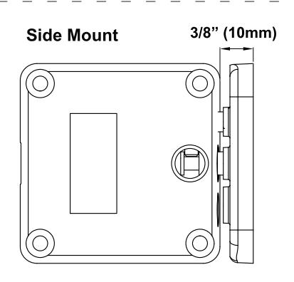
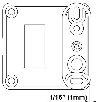
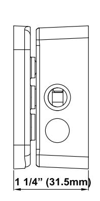
Dimensions

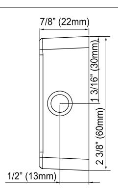
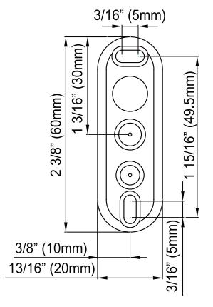
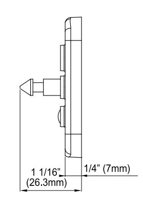
1/8" (3mm)
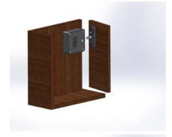
Swing Door Application (Pivoting Door Mount)
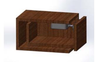
Drawer Application (Interior of Drawer)
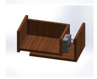
Drawer Application (Back of Drawer)


ROFU 3820 Motorized Cabinet Lock Instructions
ROFU Security International Corp. 6818 S 220th ST Kent, WA 98032 (253) 922-1828
www.ROFU.com OrderEntry@ROFU.com
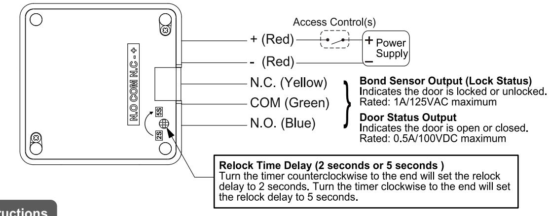
Wiring Diagram
Mounting Instructions
- 1. Mount the locking unit to the fixed porition of the cabinet or drawer with the four 5/32" x 1 1/4" (4 x32mm) flat head screws.
- 2. Install the rosette with the two 1/8" x 1/2" (3.5 x 12mm) pan head screws. Make sure the locking unit and rosette must be aligned as shown in Figure 1. When closing the cabinet or drawer door, the locking pin of the rosette must be able to engage the locking unit.
- 3. The adjustment of the rosette can be handled by the elongated holes in the rosette.
- 4. Make sure the magnet and door status sensor are aligned so that door status monitoring is enabled. (See Figure 2)
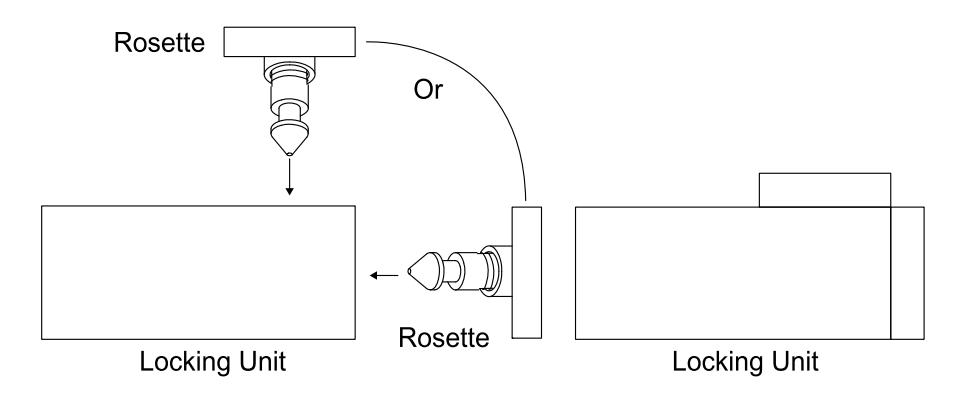
Figure 1 Mounting Position
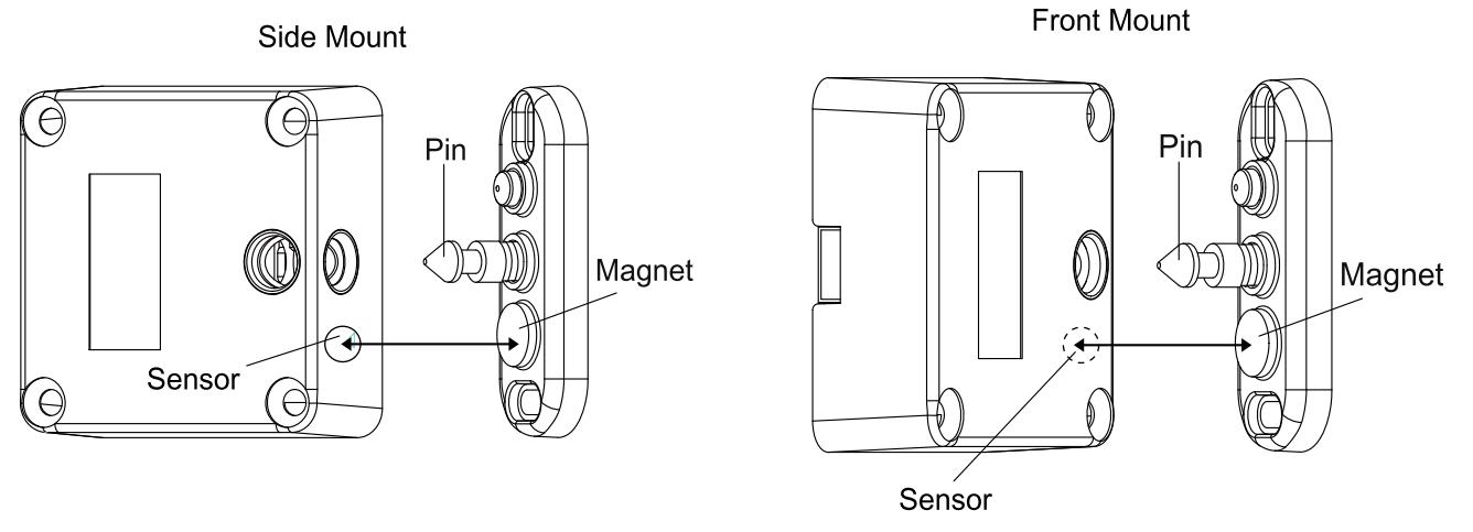
Figure 2 Alignment of Magnet and Door Status Sensor