ROFU 2470 Electric Rim Strike Installation Instructions
Open the original PDF document
View PDF

Installation Instructions ROFU 2470 Electric Rim Strike
ROFU Security International Corp. 6818 S 220th ST Kent, WA 98032 (253) 922-1828 www.ROFU.com OrderEntry@ROFU.com
The ROFU 2470 Electric Rim Strike is surface mounted and designed with the strength and durability for rim exit devices with a 3/4" throw Pullman latchbolt and a 3/4" thick metal housing. No cutting on the frame is required for installation. The strike is field selectable for fail-safe and fail-secure operation and for 12 or 24VDC. It is for indoor use only.
Pre-Installation
- Measure and mark the door latch line and the centerline of the door. See "Surface Mount Installation".
- 2. Prepare the door frame for installation.
- 3. Set either fail-safe or fail-secure operation. See page 2.
- 4. Connect to power. See "Wiring Diagram" on page 2.
Specifications
| Operating Voltage | 12/24VDC |
|---|---|
| Current Draw | 540mA/12VDC, 270mA/24VDC |
| Operating Temperature | 14°F to 120°F (-10°C~+49°C) |
| Humidity | 0~85 % non-condensing |
| Static Strength | 1500 lbs |
| Dynamic Strength | 70 ft-lbs |
| Endurance Rating |
250,000 cycles
1,000,000 cycles (Factory tested) |
| Lock Mode | Field selectable fail-safe and fail-secure |
Parts List
| Strike x 1 | Butt splice connectors x 2 |
|---|---|
| Blind nut kit x 1 | Stainless steel mounting tabsx 3 |
| Blind nuts x 2 | 24VDC cable connectorx 1 |
| Allen wrench (Hex key) x 1 | 12VDC cable connectorx 1 |
| Hex socket head cap screws x 2 | Manualx 1 |
| Philips flat head screws x 2 |
Dimensions
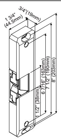
2470
Surface Mount Installation
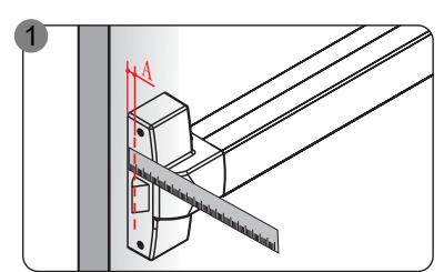
Measure latch position.
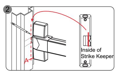
Mark latch position line on the frame. Align the marked line with the inside of strike keeper as shown.
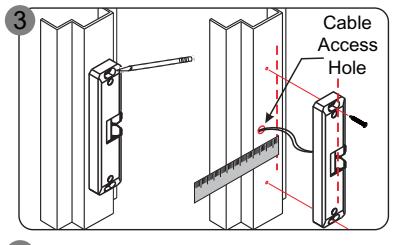
Use the strike as a template to mark the cable access hole and two mounting holes. Drill holes, connect wires, and then mount the strike with Philips flat head screws.
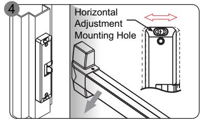
Check latchbolt interaction to see if horizontal adjustment is necessary. Adjust if needed.
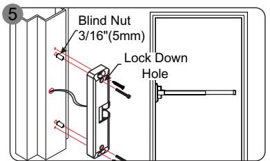
Lock down the horizontal adjustment to secure the strike. See "Horizontal Adjustment and Lockdown" on page 2.

Installation Instructions ROFU 2470 Electric Rim Strike
ROFU Security International Corp.
6818 S 220th ST Kent, WA 98032 (253) 922-1828 www.ROFU.com OrderEntry@ROFU.com
Horizontal Adjustment and Lockdown
1. Loosen the two 3/16" x 1 1/4" (5 x 32mm) mounting screws. 2. Move the strike horizontally to the appropriate position. 3. Tighten the two 3/16" x 1 1/4" (5 x 32mm) mounting screws. 4. Mark the two locking holes and remove the strike. 5. Drill holes. Install the strike and secure with blind nuts and hex screws through the locking holes. 3/8" (10mm) Mounting Screw Mounting Screw Lock Down Hole Lock Down Hole
Installing the Crimp Connectors
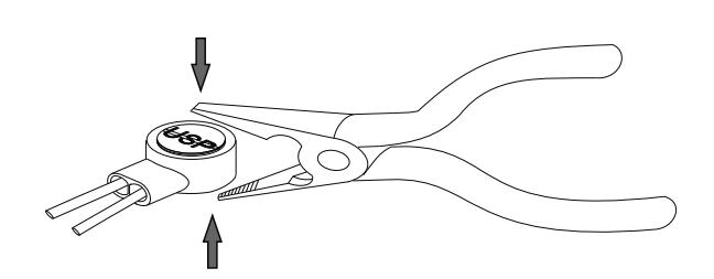
Crimp connectors are provided to make wiring connections easier and more reliable. To install the connectors:
- 1. Insert the wires into the connector.
- 2. Use a crimping tool or pliers to evenly press down on the head of the connector.
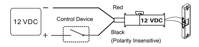
Wiring Diagrams
For 12VDC operation:
- 1. Use the included wiring connector marked 12VDC.
- 2. Plug the male wiring connector into the female wiring harness connector of the door strike
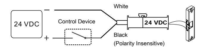
For 24VDC operation:
- 1. Use the included wiring connector marked 24VDC.
- 2. Plug the male wiring connector into the female wiring harness connector of the door strike.
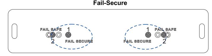
Changing Fail-Safe /Fail-Secure
Remove locking screw #1, loosen, slide and tighten sliding screw #2. Reinsert and tighten locking screw #1 to the desired fail-safe or fail-secure setting.
2 1 1 2 Fail-Safe Locking screw Sliding screw