ROFU 2420 Electric Strike Installation Instructions
Open the original PDF document
View PDF

Electric Strike Installation Instructions 2420 Series
ROFU Security International Corp. 6818 S 220th ST Kent, WA 98032 (253) 922-1828 www.ROFU.com OrderEntry@ROFU.com
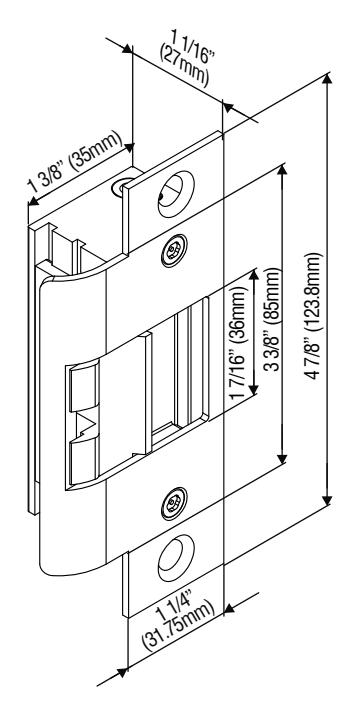
2420 series of electric strikes are designed for use with cylindrical locksets and accommodate latchbolts up to 9/16" throw. The strikes can be configured to fail-safe or fail-secure on site.
| Model |
Latch
Monitor |
Endurance
(Cycles) |
Body
Construction |
Frame |
Latch
Throw |
|---|---|---|---|---|---|
| 2420 | _ | 250,000 | Zinc Alloy | Hollow | 9/16" |
| 2420LM | • | 250,000 | Metal | (15mm) |
| Operating Voltage | 12/24VDC | ||
|---|---|---|---|
| Current Draw | 300mA/12VDC, 150mA/24VDC | ||
| Operating Temperature |
For indoor use: + 14°F to + 120°F
(-10°C to + 49°C) For outdoor use: -31°F to +151°F (-35°C to + 66°C) |
||
| Humidity | 0% to 85% Non-condensing | ||
| Latch Throw | 9/16" (15mm) maximum | ||
| Keeper Width | 1 7/16" (36mm) | ||
| Static Strength | 1500 lbs (680Kg) | ||
| Dynamic Strength | 70 ft-lbs | ||
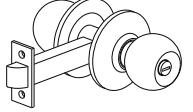

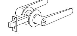
Cylindrical Lever Lockset
Wiring Diagrams
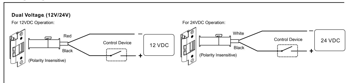
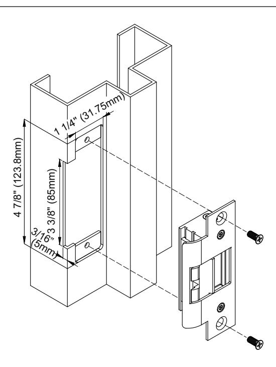
Installation on Wood and Hollow Metal Frame:
Installing the Crimp Connectors
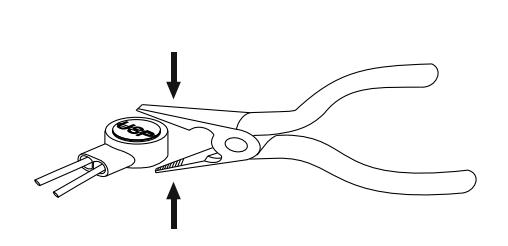
Place the wire inside the connector and use pliers to press down on the head of the connector evenly.
Fail-Safe / Fail-Secure Reversible
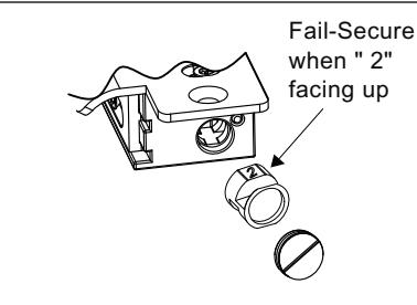
Remove the plug and take out the round screw.
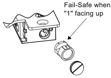
2. Reverse the round screw.

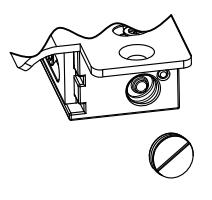
3. Put back the round screw and plug.
Installation Steps
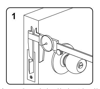
Measure the vertical and horizontal position of the latch bolt on the door leaf
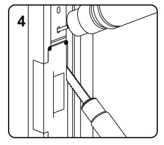
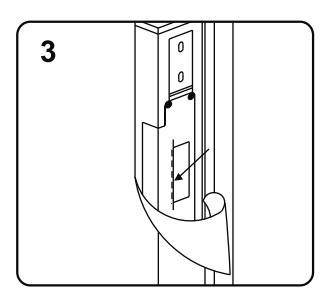
Drill and cut the frame according to the template
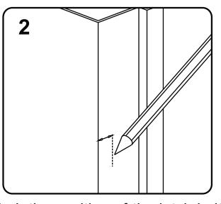
Mark the position of the latch bolt on the door jamb as shown in figure
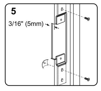
Install the mounting tabs
Align the installation template to the marked line
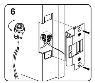
Connect to the power and test the electric strike before finally mounting the unit

Note
Please ensure that there is no back pressure on the keeper from the latch. As with most strikes this may cause the strike to bind and malfunction. It could also cause undo pressure on the solenoid and eventual failure of the strike.