ROFU 1506 Kit Electric Strike Installation Instructions
Open the original PDF document
View PDF

Electric Strike Installation Instructions
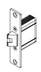
ROFU 1506 US32D & 1506 Kit
ROFU Security International Corp.
6818 S 220th ST Kent, WA 98032 (253) 922-1828 www.ROFU.com OrderEntry@ROFU.com
Specifications
■ Voltages:
1506-01G 3 to 6 VDC or 8 to 16 VAC Intermittent Duty (Intermittent use: Not to exceed 10 seconds)
1506-05G 12 VDC 1506-08G 24 VDC
Current Draw: 280mA/12VDC. 140mA/24VDC
Operating Temperature: 14° to 120°F (-10° to 49°C)
■ Humidity: 0%~85% Non-Condensing
Latch Throw: 1/2" (13mm) Keeper Width: 1-1/8" (28mm) Cycle Test: 250,000+ cycles Static Strength: 1,000 lbs (454 kg)
Strike Body: Zinc Alloy
■ Faceplate Finish:
1506 US32D Brushed Stainless Steel (No-Cut) 1506 Kit-US32D (No-Cut) & US28 (Low-Cut)
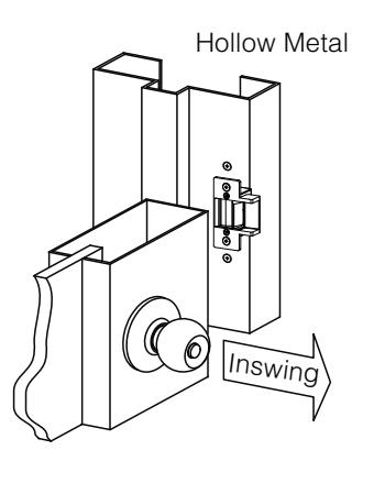
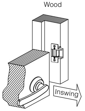
Lock Mode: Fail-secure Swing Door Direction: Inswing
(26.5<sub>mm</sub>) 2 1/8 (54mm) 2 3/4" 1 1/8 (69.8mm) (28mm (43mm) (2mm)
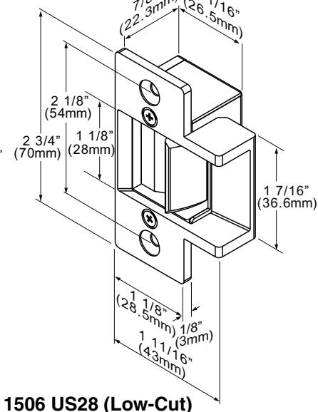
1506 US32D (No-Cut)
Available in 1506 Kit
Frame Applications

Compatible Locks
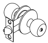
Cylindrical Lock
Door Latch
Installing the Crimp Connectors
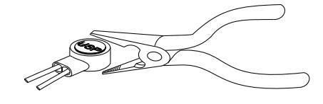
Place the wire inside the connector and use pliers to press down on the head of the connector evenly.
Installation Instructions for Wood Door Application
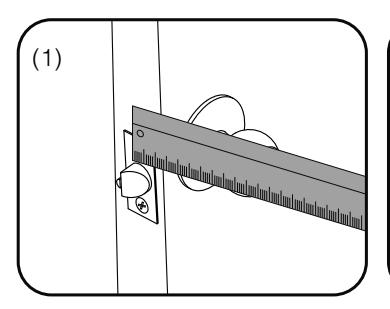
Measure latch position
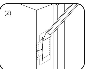
Mark latch position line
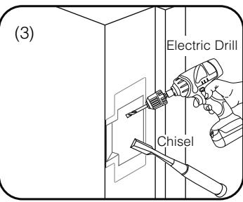
Drill and cut the frame
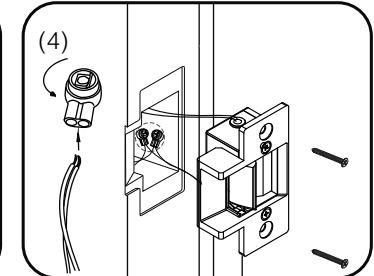
Connect the wires using the crimp connectors, then test the strike, ensure you give it correct voltage
Note: Please ensure that there is no back pressure on the keeper from the latch. As with most strike this may cause the strike to bind and malfunction. It could also cause undo pressure on the solenoid and eventual failure of the strike.