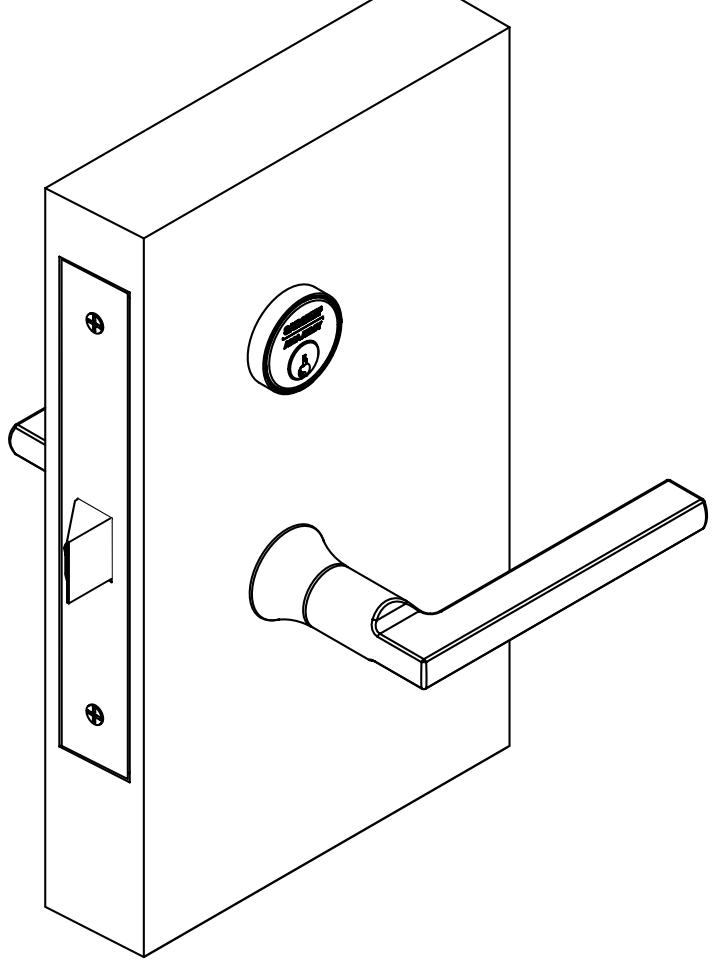
R8200 Mortise Lock with Simpli Roseless Trim Installation Instructions
Open the original PDF document
View PDFInstallation Instructions

R8200 Series
Simpli™ Roseless Trim
Mortise Lock
Warnings & Notes
All trim components shown will vary by function number Trim one-side functions - refer to instruction sheet A8031
Screw Pack with screws for lockbody, fronts and strike screws (part #77-4236)
Trim both side pack includes inside mounting plate assembly, spindle, through-bolt screws and set screw
Trim one side pack includes inside mounting plate assembly, spindle, through-bolt screws, set screw and trim one side plate

This product can expose you to lead which is known to the state of California to cause cancer and birth defects or other reproductive harm. For more information go to www.P65warnings.ca.gov.
Mortise Lock
Installation Instructions

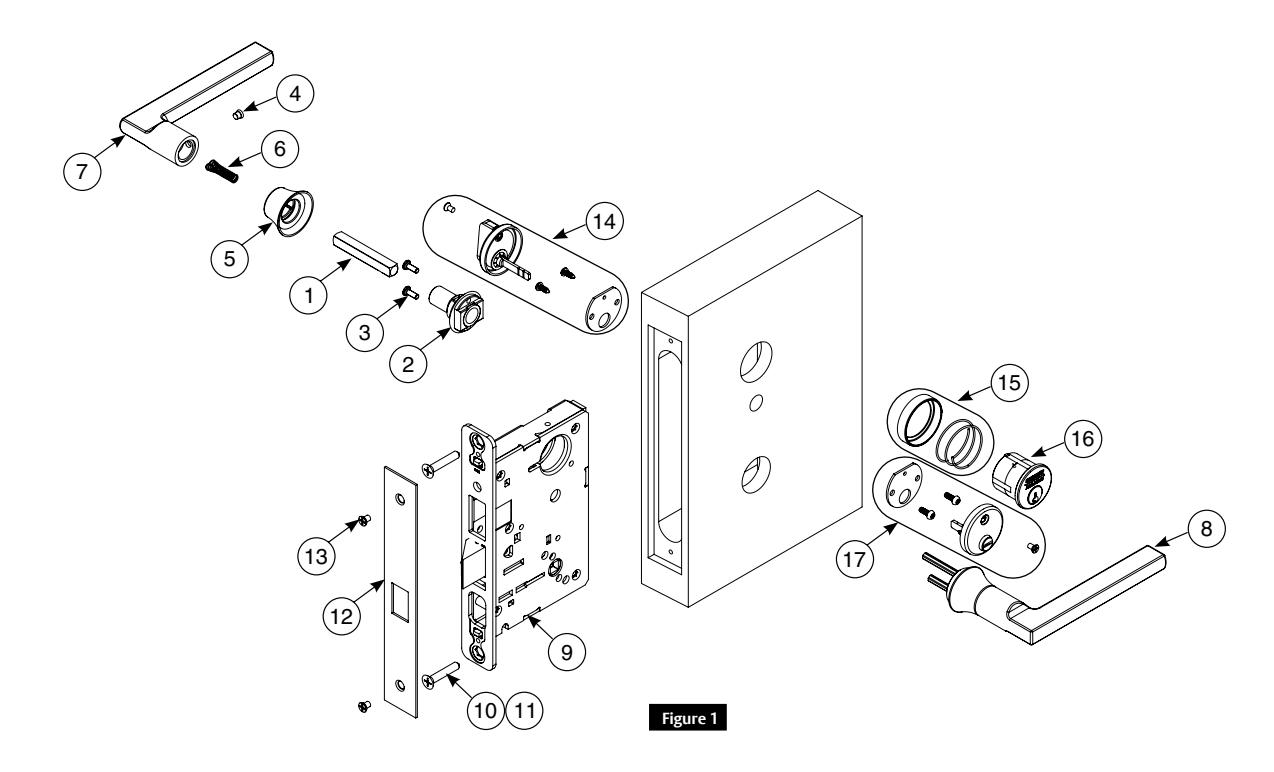
Parts List
| Part No | Description | Req. | |
|---|---|---|---|
| 1 | 82-0371 | Spindle | 2 |
| 2 | 82-4675 | Mounting plate assembly | 1 |
| 3 | 01-9376 | #8-32 x 5/8 machine screw with #6 head | 2 |
| 4 | 82-1038 | Handle screw | 1 |
| 5 | - | Lever base | 2 |
| 6 | 82-0347 | Spindle spring | 2 |
| 7 | - | Inside lever | 1 |
| 8 | - | Outside lever | 1 |
| 9 | - | Lockbody (various functions) | 1 |
| 10 | 01-1019 | Machine screw #12-24 x 1/2" | 2 |
| 11 | 01-2299 | Wood screw #12 x 1-1/4" | 2 |
| 12 | - | Outside front plate, varies by function | 1 |
| 13 | 01-1028 | Front screw #8-32 x 1/4" | 2 |
| 14 | - | Turn lever pack - 130kb | 1 |
| 15 | - |
Cylinder collar/rosette (size varies) 1KB (or
larger) |
1 |
| 16 | - | Cylinder (various key systems) | 1 |
| 17 | - | 184 x design emergency release assembly | 1 |
Tools Required
- Phillips screwdriver
- T20 Torx
- Lever base tool (provided)
Mortise Lock
Installation Instructions

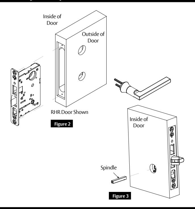
2 Install Lockbody, Outside Lever Assembly and Spindle
IMPORTANT:
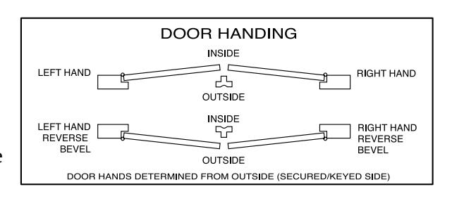
Check template A4647 to prep door for function holes, size and location. Verify strike location according to template. Clean out door pocket and door edge of any debris. Make sure handing of lock (latch and locking piece) match handing of door.
NOTE: Keep door open during installation.
- 1. Slide lockbody into door. (Figure 2)
- 2. Slide outside lever assembly through door and lockbody and hold. (Figure 2)
- 3. Insert spindle into lockbody hub. (Figure 3)
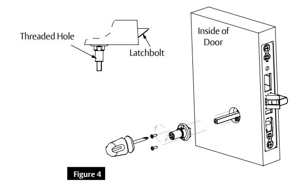
3 Install Inside Adapter and Cylinder
- 1. Slide inside adapter over spindle. Verify threaded hole in adapter faces hinge. (Figure 4)
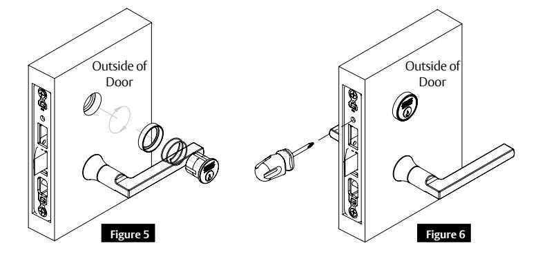
- 2. Sliding cylinder through spring and collar, thread into lockbody until flush with collar. Verify logo is straight and at top. (Figure 5)
- 3. Secure cylinder in lockbody using access hole just above deadbolt opening. (Figure 6)
A8030D 02/20 1-800-727-5477 • www.sargentlock.com
Mortise Lock
Installation Instructions

4 Secure Lockbody. Attach Collar. Install Inside Lever.
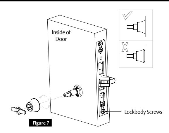
- 1. Secure lockbody in door with two (2) wood screws #12 x 1-1/4" or two (2) #12-24 x 1/2" machine screws. (Figure 7)
- 2. Attach collar to adapter by rotating clockwise using tool supplied. Assemble flush with door. (Figure 7)
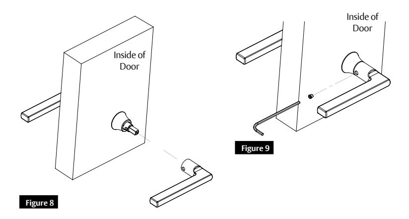
- 3. Slide lever over spindle and adapter. (Figure 8)
- 4. Secure with set screw. (Figure 9)
5 Install Strike Plate and Strike. Test Operation.
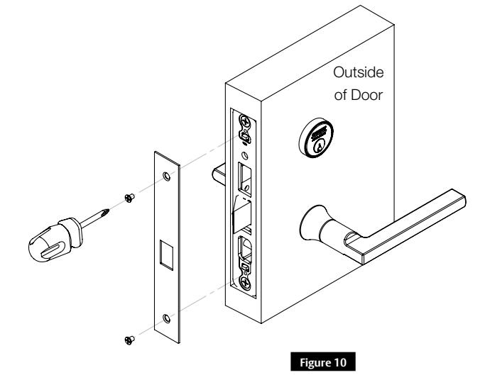
- 1. Attach outside front with two (2) #8-32 x 1/4" flat head screws. (Figure 10)
- 2. Position and secure strike in frame with screws provided.
- 3. Test lock function, both levers and cylinder prior to closing door.
A8030D 02/20 1-800-727-5477 • www.sargentlock.com
Mortise Lock
Installation Instructions

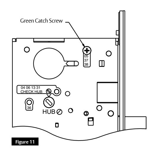
6 8200 Multi-function Options (04, 05, 06, 13, 31, 36, 37, 38)
How to Change Function of Lock:
Green catch screw must be located as designated on lock case to create desired function. (Figure 11)
Three (3) locations:
- 05, 37 and 38 function (15 function in unlocked position)
- 04, 06, 13 and 31 functions
- 36 function
NOTE: When moving green catch screw to 04, 06, 13 and 31 functions, hub position must be at 45° as shown on lock case.

#41 Cylinder is standard for both single and double cylinder functions for 1-3/4" thick door.
NOTE: Trim one-side functions always require an inside trim assembly which can be used on inside or outside of door.
| Items Needed To Create Function | |||||||||
|---|---|---|---|---|---|---|---|---|---|
| Function |
Outside
Lever |
Inside
Lever |
Trim
One Side Kit |
Outside
Cylinder |
Inside
Cylinder |
Thumb
Turn |
|||
| 04 | X | X | X | ||||||
| 05 | X | X | X | X | |||||
| 06 | X | X | X | ||||||
| 13 | X | X | |||||||
| 15 | X | X | |||||||
| 31 | X | X | X | ||||||
| 36 | X | X | X | ||||||
| 37 | X | X | X | ||||||
| 38 | X | X | X | X | |||||
Mortise Lock
Installation Instructions

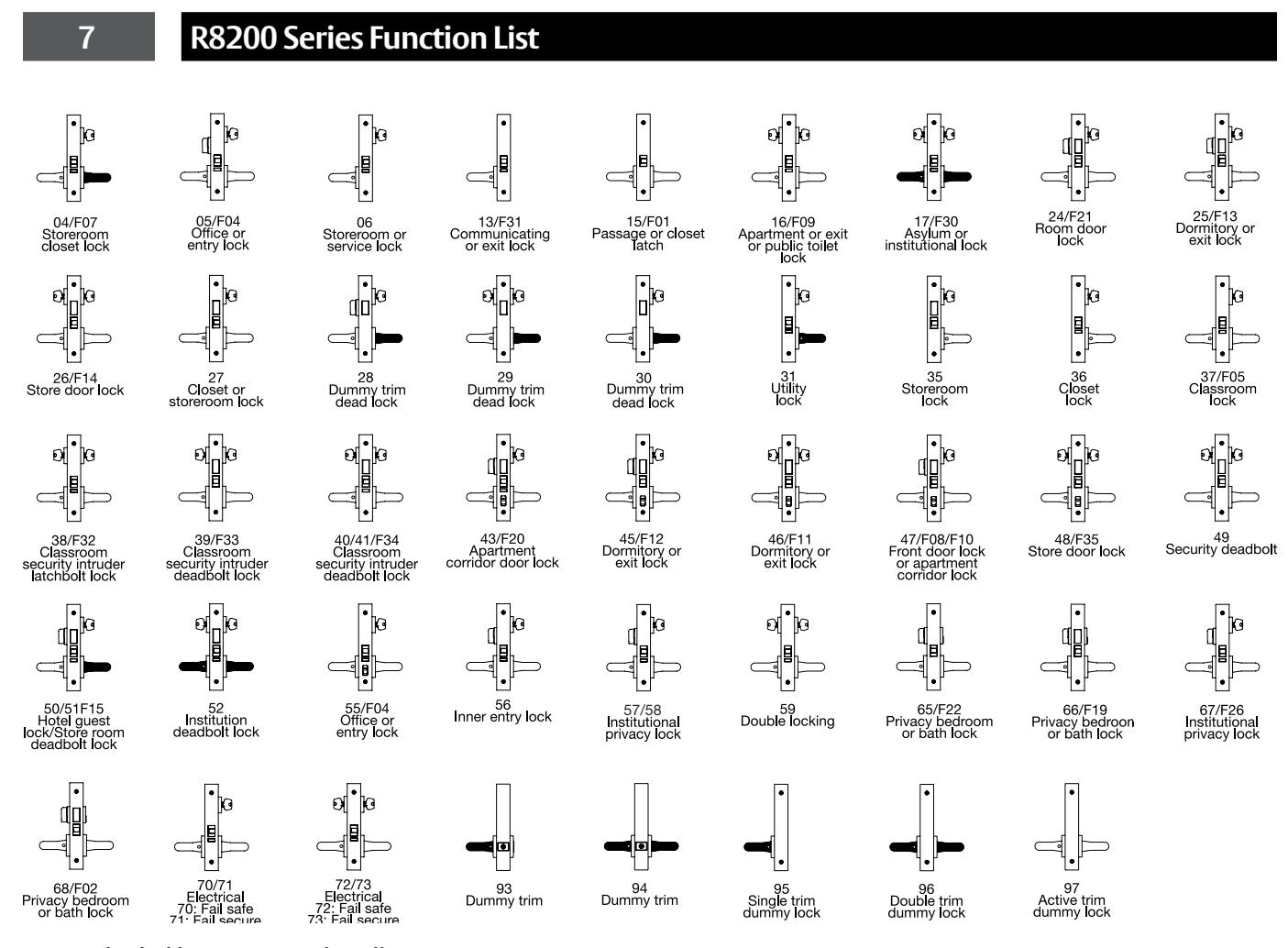
NOTE: Shaded levers are rigid at all times
Mortise Lock
Installation Instructions

8 How to Change Hand of Lockbody
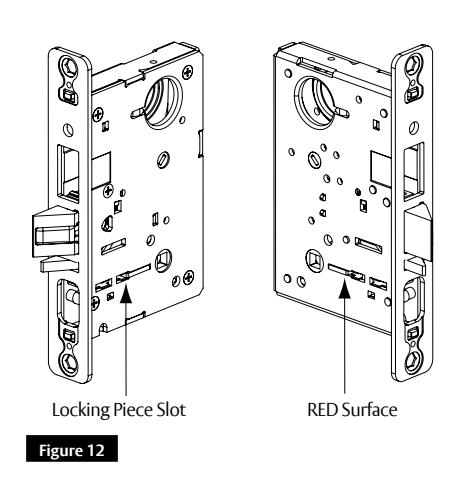
NOTE: Red surface of locking piece must face secure (keyed/locked) side of door.
To rotate locking piece:
- 1. Position lockbody with red surface of locking piece visible. (Figure 12)
- 2. Insert blade type screwdriver into locking piece slot to rotate locking piece.
- 3. Push locking piece toward back of lockbody and rotate 180° until RED surface shows on opposite side.

04, 06, 13 and 31 functions require:
- 1. Remove green catch screw.
- 2. Rotate hub 45° to vertical position.
- 3. Rotate locking piece for required hand. NOTE: Red surface faces locked side of door.
- 4. Rotate hub to original 45° position as shown on lock case.
- 5. Reinstall green catch screw.
NOTE: Beveled surface of latch must face strike. Deadlatch is self adjusting.
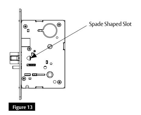
To change hand of latch:
- 1. Insert flat blade screwdriver into spade shaped slot. (Figure 13)
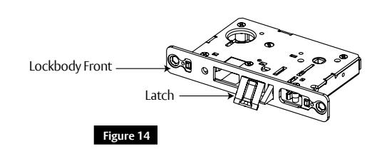
- 2. Rotate screwdriver 90º to push latch out until back of latch clears lock front.
- 3. Rotate latch 180º. Latch will re-enter lockbody. (Figure 14)
NOTE: Latch cannot be unscrewed.

SARGENT Manufacturing Company 100 Sargent Drive New Haven, CT 06511 USA 800-727-5477 www.sargentlock.com
Founded in the early 1800s, SARGENT® is a market leader in locksets, cylinders, door closers, exit devices, electro-mechanical products and access control systems for new construction, renovation, and replacement applications. The company's customer base includes commercial construction, institutional, and industrial markets.