Pulse Installation Instructions
Open the original PDF document
View PDF

Installation instructions

Company
Founded in 1983 with the aim of providing a complete range of professional products, Tecnosicurezza is now a consolidated reality in the field of locks and security systems for safes.
The experience gained in over 35 years of activity in the security sector has allowed the designing and manufacturing of high technology and reliability systems, which continue to receive the approval of an increasingly demanding clientele.
TECNOSICUREZZA is present directly on the Italian, Spanish and US markets and, through a extensive distribution network, in many European and extra-European countries.
TECNOSICUREZZA is aimed at national and international customers of primary importance, such as banks, safe manufacturers, cash in transit companies, mass market retailers and post offices.
Today TECNOSICUREZZA is a leading company focused on the customers' needs and constantly in step with technology.

| Table of contents | |
|---|---|
| COMPANY | 2 |
| TABLE OF CONTENTS | 3 |
| MODELS AND CHARACTERISTICS | 4 |
| ACCESSORIES | 4 |
| CERTIFICATIONS | 5 |
| IMPORTANT NOTES! | 9 |
| KEYPAD DIMENSIONS | 10 |
| ROTOBOLT LOCK DIMENSIONS | 11 |
| UNIVERSAL ROTOBOLT LOCK DIMENSIONS | 11 |
| STRAIGHTBOLT LOCK DIMENSIONS | 11 |
| SPRINGBOLT LOCK DIMENSIONS | 12 |
| MOTORLOCK LOCK DIMENSIONS | 12 |
| DIMENSIONI SERRATURA MOTORSPRINGBOLT | 12 |
| KEYPAD ROTATING KIT INSTALLATION INSTRUCTIONS (ACCESSORY, P.N. T3300) | 13 |
| FIXED KEYPAD INSTALLATION INSTRUCTIONS | 14 |
| ROTOBOLT LOCK INSTALLATION INSTRUCTIONS | 15 |
| STRAIGHTBOLT AND SPRINGBOLT LOCKS INSTALLATION INSTRUCTION | 16 |
| MOTORLOCK AND MOTOR SPRINGBOLT LOCKS INSTALLATION INSTRUCTIONS | 18 |
| FUNCTIONAL TEST | 19 |
| CE DECLARATIONS | 20 |
| NOTES | 21 |
| CONTACTS | 24 |

|
Models and
characteristics |
||
|---|---|---|
| Model | Variant | |
|
T6430/B/BR
– |
Pulse keypad in ABS. Black colour. Black rubber membrane foil keypad. | |
|
/B
Black colour. |
||
|
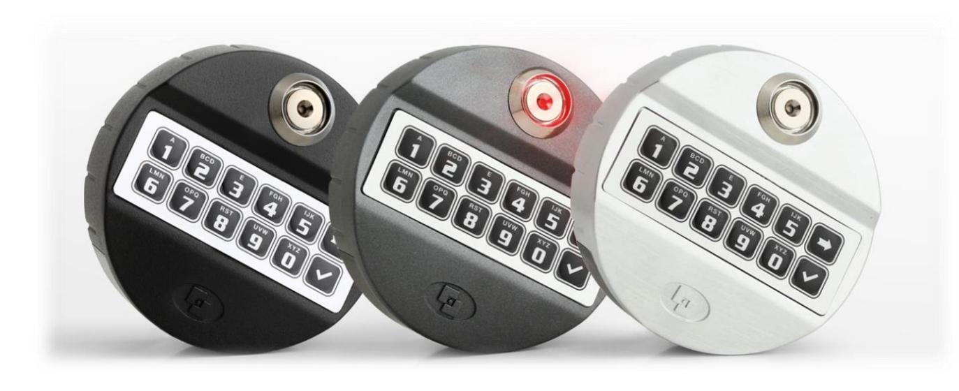
T6530
– Pulse in metal. Satin chrome colour |
/GR
with rubber membrane foil keypad in grey colour. |
|
|
/BR
with rubber membrane foil keypad in black colour. |
||
|
/DL
with Dallas key reader. |
||
Accessories
| Code | Description |
|---|---|
| T3330 | Rotating back plate kit. |
| NL1000 | Mounting adapter. |
| N077/A | Battery box with alarm interface. |
| L4001 | Large battery box for 6 size C 1.5V batteries. |
| T6005/W | Power supply interface (12Vdc). |
| T6005 |
Power supply interface (12Vdc)
with alarm interface. |
| L2666 | Knob with 6 mm square spindle. |
| N1982 |
User
Dallas key. |
Audit and programming accessories
| Code | Description | |
|---|---|---|
| N42180/T |
USB
interface. |
|
| N42170/D |
Dallas key reader with
molex connector. |
|
| N1996 |
Audit and setup
Dallas key. |
|

Certifications
SD 0 Vas SE N. M Vas: 37
50
in

Anerkennung
von Bauteilen und Systemen
of Components and Systems
Inhaber der Anerkennung Holder of the Approval TECNOSICUREZZA s.r.l. Via Cesare Battisti 276 IT-37057 Verona
Anerkennungs-Nr Approval No. Anzahl der Seiter No. of pages gültig vom /TT MM JJJJ. valid from /dd.mm yyy gültig bis ITT MM ILLUL valid until Idd mm yyyyl M 108308 09.08.2018 6 08.08.2022
Elektronisches Hochsicherheitsschloss - Klasse 2 High security electronic lock - class 2
EM20.20 und EM20.50 (Rotobolt)
in Wertbehältnissen
in secure storage units
Anerkennungsgrundlagen Basis of the Approval VdS 2344:2014-07 VdS 2396:2014-07 EN 1300:2013-11
Köln, den 02.08.2018
Dr. Reinermann
Geschäftsführer Managing Director
i. V. Prudent
Leiter der Zertifizierungsstelle Head of Certification Body

Die Anerkennung
umfasst nur das angegebene Bauteil/System in der zur Prüfung eingereichten Ausführung
- mit den Bestandteilen nach Anlage 1,
- dokumentiert in den technischen
- Unterlagen nach Anlage 2, zur Verwendung in den angege-benen Einrichtungen der Brand-schutz- und Sicherungstechnik
Bei der Anwendung des Gegenstan des der Anerkennung sind die Hinweise nach Anlage 3 zu beachten
Das Zertifikat darf nur unverändert und mit sämtlichen Anlagen verviel-fältigt werden. Alle Änderungen der Voraussetzungen für die Anerken-nung sind der VdS-Zertifizierungsstelle - mitsamt den erforderlichen Unterlagen - unverzüglich zu über-mitteln.
This Approval
is valid only for the specified compo nent/system as submitted for testing
- together with the parts listed in
- together with the parts listed if enclosure 1 documented in the technical documents according to enclosure 2 for the use in the specified fire
- protection and security installa-
when using the subject of the approval the notes of enclosure 3 shall be observed. This certificate may only be reproduced in its present form without any modifications including all enclosures. All changes of the underlying conditions of this approval shall be reported at once to the VdS certification body including the control of the very subject to the VdS certification body including the required documentation
VdS Schadenverhütung GmbH Zertifizierungsstelle Amsterdamer Str. 174 D-50735 Köln
Ein Unternehmen des Gesamt-Ein Unternehmen des Gesamt-verbandes der Deutschen Ver-sicherungswirtschaft e.V. (GDV), durch die DAkkS akkreditiert als Zertifizierungsstelle für Produkte in den Bereichen Brandschutz und Sicherungstechnik
A company of the German Insuran Association (GDV) accredited by DAkkS as certification body for fire protection and security products
II Pulse 10 eng 5 of 24
Anerkennung
von Bauteilen und Systemen
of Components and Systems
Inhaber der Anerkennung TECNOSICUREZZA s.r.l. Via Cesare Battisti 276 IT-37057 Verona
Anerkennungs-Nr Approval No Anzahl der Seiten M 109323
gültig vom /// MM //// valid from /// mm 09.08.2018
gültig bis (TT MM JJJJ) valid until (dd mm ywd 08.08.2022
Gegenstand der Anerkennung Subject of the Approval
Elektronisches Hochsicherheitsschloss - Klasse 2 High security electronic lock - class 2
5
EM35.20 und EM35.50 (Straight Bolt)
Verwendung
in Wertbehältnissen
in secure storage units
Anerkennungsgrundlagen Basis of the Approval VdS 2344:2014-07 VdS 2396:2014-07 EN 1300:2013-11
Köln, den 02.08.2018
( DAkkS Deutsche Akkreditierungsstelle D-ZE-11149-01-01
Dr. Reinermann Geschäftsführer Managing Director
i. V. Prudent Leiter der Zertifizierungsstelle Head of Certification Body

Die Anerkennung
umfasst nur das angegebene Bauteil/System in der zur Prüfung eingereichten Ausführung
- mit den Bestandteilen nach
- mit den Bestamuerten nach Anlage 1, dokumentiert in den lechnischen Unterlagen nach Anlage 2, zur Verwendung in den angege-benen Einrichtungen der Brand-schutz- und Sicherungstechnik
Bei der Anwendung des Gegenstan-des der Anerkennung sind die Hin-weise nach Anlage 3 zu beachten.
Das Zertifikat darf nur unverändert und mit sämtlichen Anlagen vervielfältigl werden. Alle Änderungen der Voraussetzungen für die Anerken-nung sind der VdS-Zertifizierungsstelle - mitsamt den erforderlichen Unterlagen - unverzüglich zu über-mitteln.
This Approval
is valid only for the specified component/system as submitted for testing
- together with the parts listed in
- enclosure 1 documented in the technical documents according to
- enclosure 2 - for the use in the specified fire protection and security installa-tions.
When using the subject of the approval the notes of enclosure 3 shall be observed.
This certificate may only be reproduced in its present form without any modifications including all enclosures. All changes of the underlying conditions of this approval shall be reported at once to the VdS certification body including the required documentation.
VdS Schadenverhütung GmbH
Zertifizierungsstelle Amsterdamer Str. 174 D-50735 Köln
Ein Unternehmen des Gesamtverbandes der Deutschen Versicherungswirtschaft e.V. (GDV), durch die DAkkS akkreditiert als Zertifizierungsstelle für Produkte in den Bereichen Brandschutz und Sicherungstechnik
A company of the German Insurance Association (GDV) accredited by DAkkS as certification body for fire protection and security products

10
Anerkennung
von Bauteilen und Systemen
of Components and Systems
Inhaber der Anerkennung TECNOSICUREZZA s.r.l.
Via Cesare Battisti 276 IT-37057 Verona
Anerkennungs-Nr Approval No. Anzahl der Seiter gültig bis /TT.MM.JJJJ/ gültig vom /TT.MM.JUU/ M 112303 4 24.01.2016 23.01.2020
Gegenstand der Anerkennung Subject of the Approval
Elektronisches Hochsicherheitsschloss - Klasse 2 High security electronic lock - class 2
EM6050
Verwendung
in Wertbehältnissen
in secure storage units
Anerkennungsgrundlagen Basis of the Approval VdS 2344:2014-07 VdS 2396:2014-07 EN 1300:2013-11
Köln, den 06.01.2016


Geschäftsführer Managing Director

ppa. Urban Leiter der Zertifizierungsstelle Head of Certification Body

Die Anerkennung
umfasst nur das angegebene Bauteil/System in der zur Prüfung eingereichten Ausführung
- mit den Bestandteilen nach
- mit den Bestandtenen nach Anlage 1, dokumentiert in den technischen Unterlagen nach Anlage 2, zur Verwendung in den angege-benen Einrichtungen der Brand-schutz- und Sicherungstechnik.
Bei der Anwendung des Gegenstan-des der Anerkennung sind die Hin-weise nach Anlage 3 zu beachten.
Das Zertifikat darf nur unverändert und mit sämtlichen Anlagen verviel-fältigt werden. Alle Änderungen der Voraussetzungen für die Anerken-nung sind der VdS-Zertifizierungs-stelle – mitsamt den erforderlichen Unterlagen - unverzüglich zu übermitteln.
This Approval
is valid only for the specified compo-nent/system as submitted for testing
- together with the parts listed in enclosure 1 documented in the technical
- documents according to
- enclosure 2 for the use in the specified fire protection and security installa-
When using the subject of the approval the notes of enclosure 3
shall be observed. This certificate may only be reproduced in its present form without any modifications including all enclosures. All changes of the underlying conditions of this approval shall be reported at once to the VdS certification body including the required documentation.
VdS Schadenverhütung GmbH
Zertifizierungsstelle Amsterdamer Str. 174 D-50735 Köln
Ein Unternehmen des Gesamtverbandes der Deutschen Ververannes der Deutschen ver-sicherungswirtschaft e.V. (GDV), durch die DAkkS akkreditiert als Zertifizierungsstelle für Produkte in den Bereichen Brandschutz und Sicherungstechnik
A company of the German Insurance Association (GDV) accredited by DAkkS as certification body for fire protection and security products
II Pulse 10 eng 7 of 24

CERTIFICATE OF COMPLIANCE
Certificate Number 20130131-BP10647 Report Reference BP10647-20130131
Issue Date 2013-JANUARY-31
Issued to: TECNOSICUREZZA SRL
VIA CESARE BATTISTI 276
37057 SANGIOVANNI LUPATOTO VR ITALY
This is to certify that HIGH-SECURITY ELECTRONIC LOCKS, TYPE 1
representative samples of Model T6530, may be followed by "G" or "B", may be
followed by "R", may be followed by "DL", and followed by
EM20-XX or EM35-XX.
Subassembly – Model Pulse, keypad entry unit.
Have been investigated by UL in accordance with the
Standard(s) indicated on this Certificate.
Standard(s) for Safety: UL Subject 2058, High Security Electronic Locks
Additional Information: See the UL Online Certifications Directory at
www.ul.com/database for additional information
Only those products bearing the UL Listing Mark should be considered as being covered by UL's Listing and Follow-Up Service.
The UL Listing Mark generally includes the following elements: the symbol UL in a circle:
with the word "LISTED"; a control number (may be alphanumeric) assigned by UL; and the product category name (product identifier) as indicated in the appropriate UL Directory.
Look for the UL Listing Mark on the product.
William R. Carney, Director, North American Certification Programs
UL LLC
Any information and documentation involving UL Mark services are provided on behalf of UL LLC (UL) or any authorized licensee of UL. For questions, please contact a local UL Customer Service Repres

Important notes!
- Before installing this product, please read carefully the installation and operating instructions.
- Locks can be installed in all traditional safes.
- Lock has to be mounted on secure storage metal (preferred steel) units only.
- Locks must be protected against external attacks, for this reason it is recommended to install them on the door away from any through holes.
- Any electronic part must be properly protected and not easily accessible even when the door is open.
- Locks have been developed to work correctly in a temperature range from -5 ° C to + 50 ° C and in an environment with non-condensing humidity between 25% and 90%.
- The mounting dimensions are standard (magic module).
- For the installation of the keypad and lock, use only the screws provided by Tecnosicurezza. Any other screw must be approved in advance.
- Locks are supplied with metric (M6) mounting screws. Upon request, Imperial 1/4-20 UNC format mounting screws are available.
- The type of material and the length of the screws must, in any case, be selected so as to guarantee long life and reliability.
- Tighten the screws so that the lock is firmly fixed to the mounting surface (recommended torque between 2.5 and 5.5 Nm).
- The mounting surface must be perfectly flat.
- In order to prevent loosening of the screws it is recommended the use of LOCTITE® threadlocker and/or specific washers positioned under the head of the fixing screw.
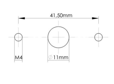
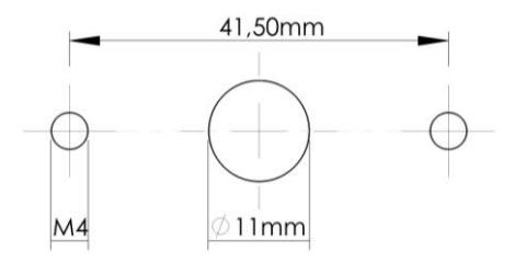
- The diameter of the passage hole for the connection cable or the spindle must not exceed 11 mm.
- The hole must be completely cleaned of drill dust and no edge should be sharp.
- Lock must not be lubricated.
II_Pulse_10_eng 9 of 24

- In the locked position, the distance between the bolt and the boltwork part that is moving the lock bolt must comply with the following specifications for each type of lock.
- Any component to be fixed to the lock bolt must be previously approved by Tecnosicurezza before installation. In any case, the maximum load must not exceed 2.5 N.
- Secure the cables away from moving parts by using cable ties and cable ties bases.
- If placed in normal domestic or office environments, the locks do not require particular maintenance; in any case, after 10,000 opening/locking cycles, it is recommended to run a test that verifies the correct and complete operation of the product.
- Use only DURACELL™ 9 Volt Alkaline batteries, or battery holders with DURACELL™ 1.5 Volt Alkaline batteries. Alternatively, it is also possible to use a stabilized 12V - 1A power supply (p.n. N1212) with relative power supply interface (p.n. T6005/W or p.n. T6005).
- A series of acoustic signals during opening indicate a low battery level. In this case, the battery must be replaced.
Keypad dimensions

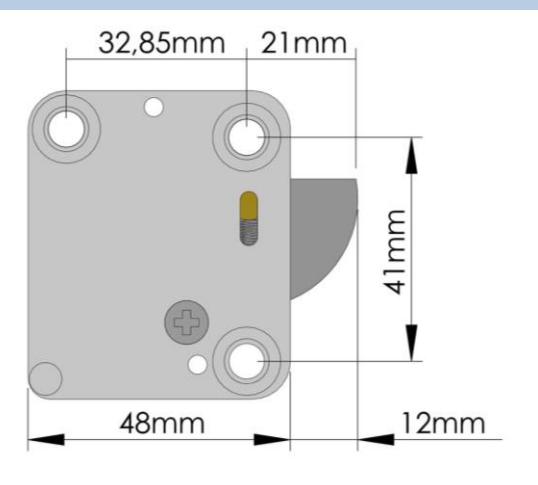
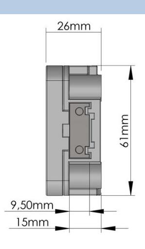
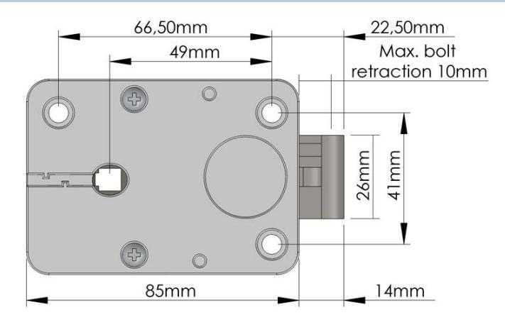
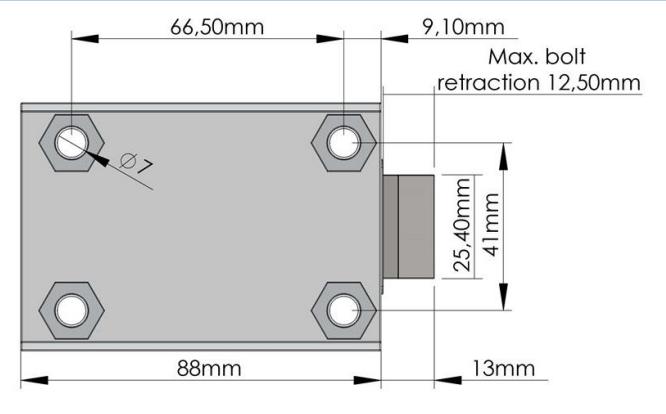
RotoBolt lock dimensions
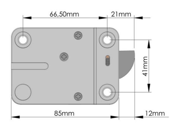
Universal RotoBolt lock dimensions
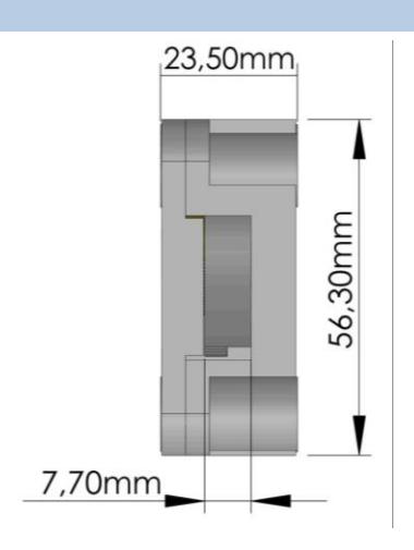
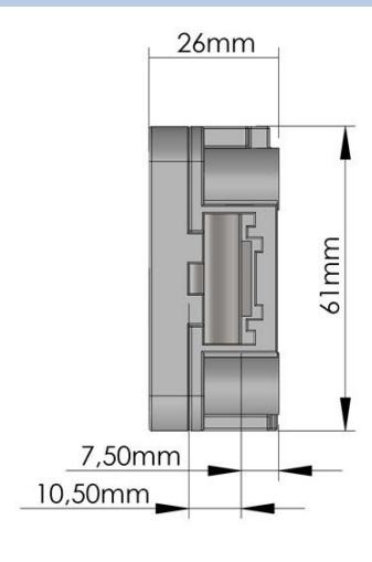
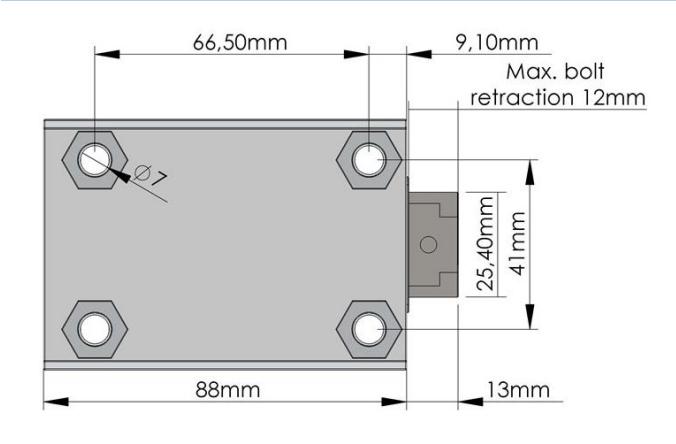
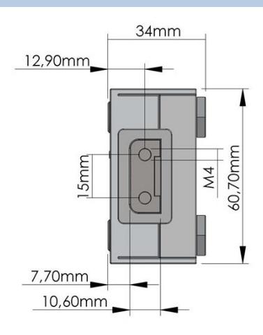
StraightBolt lock dimensions
II_Pulse_10_eng 11 of 24

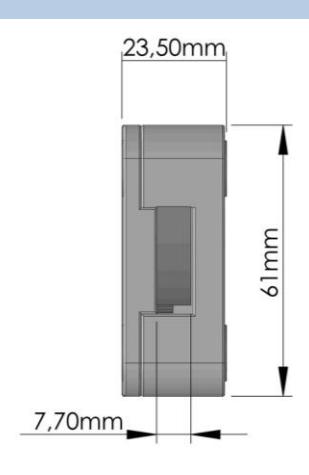
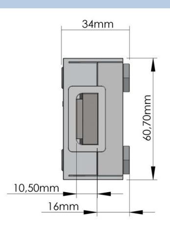
SpringBolt lock dimensions
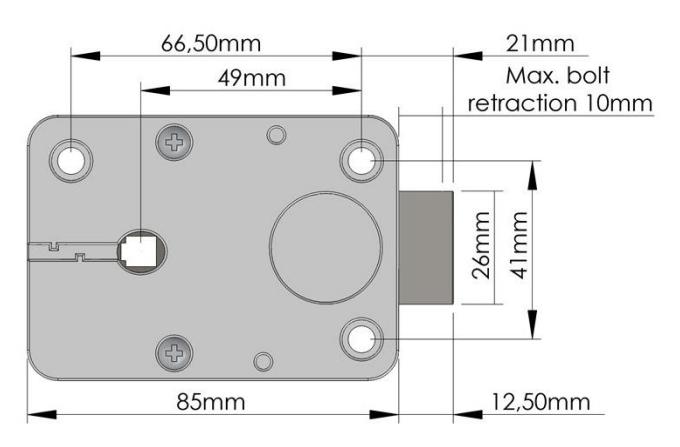
MotorLock lock dimensions
Dimensioni serratura MotorSpringBolt

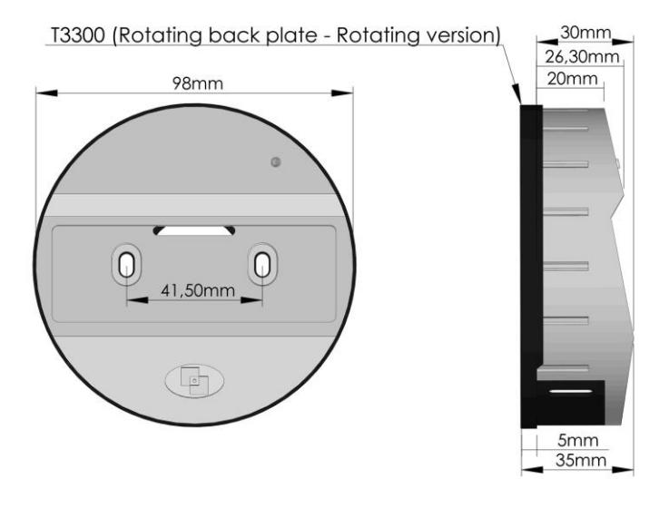
Keypad rotating kit installation instructions (accessory, p.n. T3300)
The rotation kit consists of 2 bushings, 2 M4 countersunk screws, 1 plastic pin, 1 spring and 1 rotating backplate.
(Imperial screws 8-32 UNC are available on request.)
Cut the grooved shaft to the appropriate length: measure door thickness (from mounting surface of the entry unit to the mounting surface of the lock) and add 26 mm (1"). Prepare the mounting and cable holes.
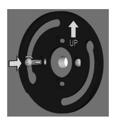
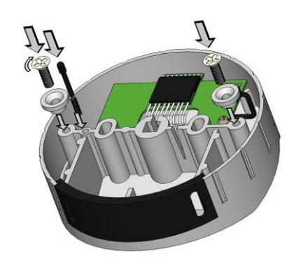
Fix the screws (M4) and the rotating backplate, positioning the latter on the side marked "UP". Fix the bushings to the keypad housing using the supplied screws.
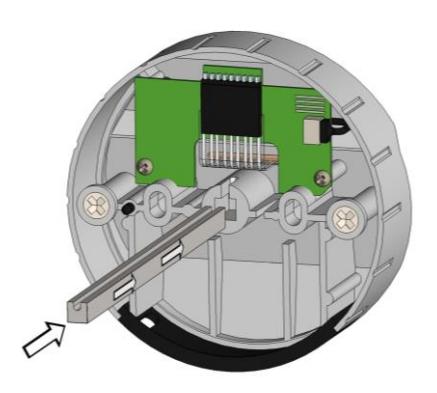
Insert the pin completely in the spring and then place it into the specific hole in the case. Insert the grooved shaft, with the cutting edge first, all the way into the keypad housing.
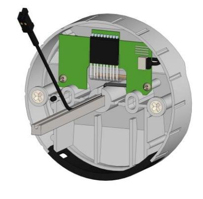
Place the connection cable inside the groove in the spindle.
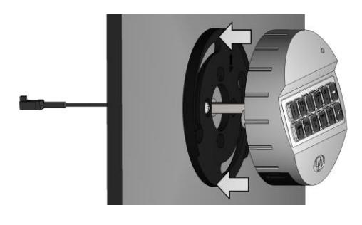
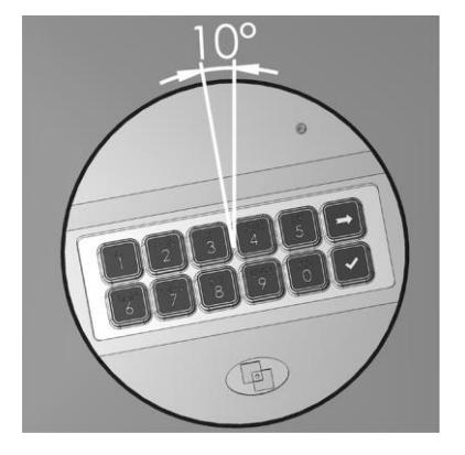
Insert the cable and the spindle inside the spindle hole made in the door, keeping the keypad in angled position (10:00 o' clock) hook the keypad to the rotating backplate.
Then turn unit clockwise into straight position at 12:00 o' clock until you hear a click, reaching the final position.
II_Pulse_10_eng 13 of 24
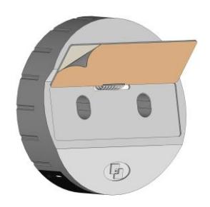
Remove the release liner placed under the membrane and apply the latter on the keypad case.
Connect a battery to the battery connector inside the keypad battery compartment or, if provided, connect the battery pack to the lock connector "BAT" (connector 2 in the case of a MotorLock or Motor SpringBolt lock).
Fixed keypad installation instructions
Insert the keypad cable inside the hole on the safe door and connect it to the lock connector "ENT" (connector 1 in the case of a MotorLock or Motor SpringBolt lock).
Lift the keypad membrane and, making sure that the connection cable and the battery cable are not damaged by the keypad case, fix the screws to the relative threaded holes on the safe door.
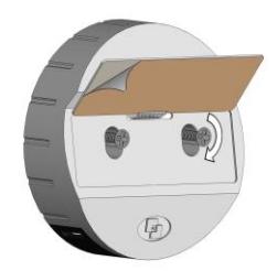
Remove the release liner placed under the membrane and apply the latter on the keypad case. Connect a battery to the battery connector inside the keypad battery compartment or, if provided, connect the battery pack to the lock connector "BAT" (connector 2 in the case of a MotorLock or Motor SpringBolt lock).

RotoBolt lock installation instructions
The RotoBolt lock is a swingbolt lock whose block is carried out by a motor; it can be installed in all 4 directions, even upside down.
By entering a valid code, the lock electronic removes the blocking for 3 seconds and the boltwork can be moved into open position by pushing the bolt inside the lock case.
The bolt automatically secures when the safe handle, or the safe door mechanism, is brought to the locked position.
If the RotoBolt lock is used in conjunction with other locks, the safe door mechanism must ensure the closure of the RotoBolt before the other locks.
The lock can be mounted in all four mounting directions (RH, LH, VU, VD).
Furthermore, by flipping over the lock, both locking directions can be realized (RH/LH).
In the locked position the distance between the RotoBolt bolt and the RotobBolt part that is moving the lock bolt should be approximately 1 mm.
The bolt must be able to move freely without force being applied to it.
The maximum load applicable to the bolt must not exceed 1KN. Contact Tecnosicurezza in case of heavier loads.
Connect the keypad cable to the lock connector "ENT", making sure it is fully inserted and locked.
Any alarm interface or battery holder will be connected to the lock connector "BAT".
To remove the cable, bring the connector upwards and carefully pull it out.
II_Pulse_10_eng 15 of 24
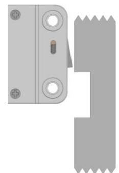
StraightBolt and SpringBolt locks installation instruction
StraightBolt and SpringBolt locks are locks with, respectively, a dead bolt and a spring bolt, whose block is carried out by a motor.
By entering a valid code, the lock electronic removes the blocking for 3 seconds and the boltwork can be moved into open position by turning the spindle inserted in the lock.
The spindle can be connected to a knob, a handle or directly to the keypad if equipped with a rotation kit. In the latter case it must be used the specific rotation kit T3300. When the spindle is brought to the locked position, the bolt comes out ensuring the lock is locked.
The StraightBolt and SpringBolt locks can be mounted in all four mounting directions.
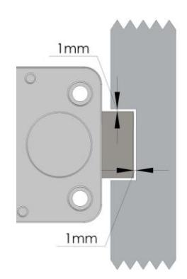
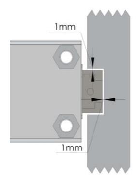
In the locked position, there should be approximately 1 mm clearance between the lock bolt and the cavity in the blocking bar of the boltwork. The bolt must be able to move freely without force being applied to it.
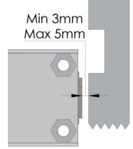
In open position, there should be minimum 3mm and maximum 5 mm clearance between the lock bolt and the blocking bar of the boltwork.
The maximum load applicable to the bolt must not exceed 1KN. Contact Tecnosicurezza in case of heavier loads.
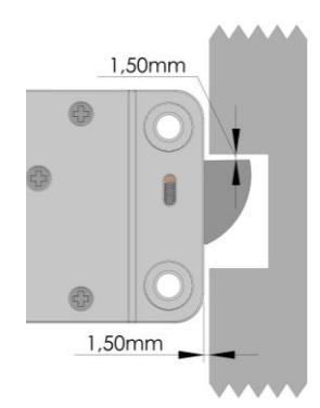
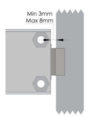
The spring-latch version (SpringBolt) is specially designed to ensure self locking when the door closes.

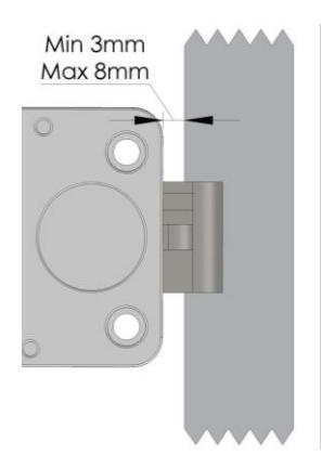
The distance between the SpringBolt lock and the locking edge must be between a minimum of 3 mm and a maximum of 8 mm.
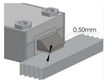
When locked, there must be a 0.5mm gap between lock bolt and locking surface.
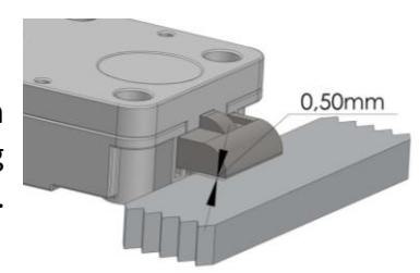
The spindle must be inserted between a minimum of 7 mm to a maximum of 12 mm inside the lock.
WARNING: do not insert the spindle up to the lid of the lock, but leave some margin to allow the movement of the cable and to prevent any damage.
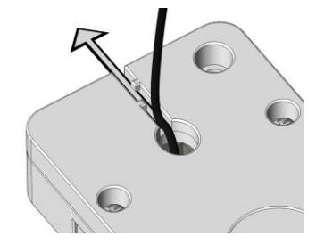
Make sure the cable is fully inserted and locked in the groove of the spindle. Remove any residues deriving from the cutting of the spindle that could damage the cable. Insert the cable connector into the square hole present in the bottom of the lock and make it come out from the opposite side.
Secure the cable, avoiding to stretch it too much, inside the specific groove on the lock cover and fix the lock using the appropriate mounting screws.
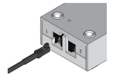
Connect the keypad cable to the lock connector "ENT", making sure it is fully inserted and locked. Any alarm interface or battery holder will be connected to the lock connector "BAT". To remove the cable, bring the connector upwards and carefully pull it out.
II_Pulse_10_eng 17 of 24

MotorLock and Motor SpringBolt locks installation instructions
MotorLock and Motor SpringBolt locks are locks with, respectively, a motor driven dead bolt and a motor driven spring bolt, whose block is carried out by a motor.
By entering a valid code, the motor retracts the bolt which remains in the open position for about 8 seconds and then automatically returns to the locked position.
If the manual relocking option is selected, the bolt closes by pressing any button.
In the locked position, there should be approximately 1 mm clearance between the lock bolt and the cavity in the blocking bar of the boltwork. The bolt must be able to move freely without force being applied to it.
In open position, there should be minimum 3mm and maximum 5 mm clearance between the lock bolt and the blocking bar of the boltwork.
The spring-latch version ( Motor SpringBolt) is specially designed to ensure self locking when the door closes.
The distance between the SpringBolt lock and the locking edge must be between a minimum of 3 mm and a maximum of 8 mm.

Connect the keypad cable to the lock connector "1", making sure it is fully inserted and locked.
Any alarm interface or battery holder will be connected to the lock connector "2".
To remove the cable, bring the connector upwards and carefully pull it out.

Functional test
To be carried out with the door open.
MEMBRANE TEST:
Press and hold button 5 until the double beep (the LED will remain on).
Slowly enter all the buttons according to the sequence below:
[1]-[2]-[3]-[4]-[5]-[6]-[7]-[8]-[9]-[0]
A double beep after pressing each single button indicates that the keypad correctly communicates with the lock.
A long beep indicates an electronic problem (in this case please contact the technical assistance).
ELECTRONIC / MECHANICAL TEST:
OPENING:
Enter the opening code (standard code 123456 or simply 1 if the lock is in pre-setup mode).
The lock emits a double beep. You will hear a long beep in case of incorrect code.
With RotoBolt and MotorLock locks, turn the safe door handle to the open position.
With StraightBolt and SpringBolt locks, rotate the knob or the keypad according to the type of installation and move the lock bolt to the open position.
For all types of locks the bolt must be able to move freely.
LOCKING:
With RotoBolt and MotorLock locks, turn the safe door handle to the locked position. Lock bolt must fully extend and ensure locking.
With MotorLock locks with manual relocking, turn the door handle towards the locked position and press any button.
With StraightBolt locks, turn the knob/keypad to the locked position.
For all types of locks, at the end of the operation the bolt must fully extend and ensure locking.
Repeat the functional test several times before locking the safe door.
Failure to follow these installation instructions or opening the lock by personnel not authorized by Tecnosicurezza will void the warranty.
II_Pulse_10_eng 19 of 24

CE declarations
DICHIARAZIONE CE DI CONFORMITA' CE DECLARATION OF CONFORMITY
Pulse: T65-xx
Il sottoscritto Franco Miller, in veste di Presidente CdA e Legale Rappresentante della società Tecnosicurezza s.r.l. , con sede in San Giovanni Lupatoto (Verona) Via Cesare Battisti 276, dichiara sotto la propria responsabilità, che il suddetto prodotto soddisfa per progettazione e costruzione i requisiti delle direttive di: compatibilità elettromagnetica 2014/30/EU e RoHS 2 UE/2015/863 . La conformità è stata verificata con l'ausilio delle seguenti norme armonizzate:
EN 61000-6-3, EN50130-4,EN 61000-4-2, EN 61000-4-3, EN 61000-4-4, EN 61000-4-5, EN 61000-4-6, EN 61000-4-11, EN 61000-6-1, EN55022
The undersigned Mr Franco Miller as Chairman and Legal Representative of the company Tecnosicurezza s.r.l. , located in San Giovanni Lupatoto (Verona) Via Cesare Battisti 276, declare herewith on our own responsibility that the above-mentioned product meets the requirements of the UE/2015/863 RoHS 2, 2014/30/EU Electromagnetic Compatibility for what concerns engineering and construction. Conformity has been controlled with the aid of the following harmonized standards:
EN 61000-6-3, EN50130-4,EN 61000-4-2, EN 61000-4-3, EN 61000-4-4, EN 61000-4-5, EN 61000-4-6, EN 61000-4-11, EN 61000-6-1, EN55022
Verona - Italy, 25/07/2018
Franco Miller Board Chairman
20 of 24 II_Pulse_10_eng


| NOTES | |
|---|---|
II_Pulse_10_eng 21 of 24


| NOTES | ||


| NOTES | |
|---|---|
II_Pulse_10_eng 23 of 24

Correct disposal of this product: (Waste Electrical & Electronic Equipment)
Applicable in the European Union and other European countries with separate collection systems.

This marking displayed on the product or its literature indicates that it should not be disposed with other wastes at the end of its working life.
To prevent possible harm to the environment or human health from uncontrolled waste disposal, please separate this from other types of wastes and recycle it responsibly to promote the sustainable reuse of material resources.
Contacts
| GLOBAL HEADQUARTERS | USA HEADQUARTERS | SPAIN HEADQUARTERS |
|---|---|---|
| Tecnosicurezza SpA | Tecnosicurezza Inc. | Tecnosicurezza Sa |
| Via Cesare Battisti. 276 | 50, Thomas Lane | C/Menor, 4 - Nave 10 |
|
37057 San Giovanni Lupatoto
Verona |
Versailles, KY 40383 |
Pol. Ind La Mina 28770
Colmenar Viejo |
| Tel.+39 045 826 64 70 | Tel.+1 859 490 89 30 | Tel.+34 91 804 33 91 |
| Fax. +39 045 826 64 69 | Fax.+34 91 804 32 63 | |
| info@tecnosicurezza.it | info@usatecno.com | info@tecnosicurezza.es |