Profile Series v.G1.5 Mortise Dorm Lock Installation & Programming Instructions
Open the original PDF document
View PDF


A7861C
11/17
Table of Contents
| 1 | Warning2 | |
|---|---|---|
| 2 | General Description3 | |
| 3 |
Specifications
3 |
|
| 4 |
Features
3 |
|
| 5 |
Parts Breakdown
4 |
|
| 6 |
Installation Instructions
6 |
|
| 7 | RF Technology Lock15 | |
| 8 |
Hardwire Wiring Options
16 |
|
| 9 |
Operational Check
21 |
|
Warning 1
Changes or modifications to this unit not expressly approved by the party responsible for compliance could void the user's authority to operate the equipment.
This device complies with Part 15 of the FCC Rules. Operation is subject to the following two conditions: (1) this device may not cause harmful interference, and (2) this device must accept any interference received, including interference that may cause undesired operation.
Note: This equipment has been tested and found to comply with the limits for a Class B digital device, pursuant to Part 15 of the FCC Rules. These limits are designed to provide reasonable protection against harmful interference in a residential installation.
This equipment generates, uses and can radiate radio frequency energy and if not installed and used in accordance with the instructions, may cause harmful interference to radio communications. However, there is no guarantee that the interference will not occur in a particular installation. If this equipment does cause harmful interference to radio or television reception, which can be determined by turning the equipment off and on, the user is encouraged to try to correct the interference by one or more of the following measures:
- Reorient or relocate the receiving antenna
- Increase the separation between the equipment and receiver
- Connect the equipment into an outlet on a circuit different from that to which the receiver is connected
- Consult the dealer or an experienced TV technician for help
This Class B digital apparatus complies with Canadian ICES-003.
Cet appareil numérique de la classe B est conforme avec la norme NMB-003 du Canada.

To comply with "Fire Listed" doors, the batteries must be replaced with alkaline batteries only. Do not install batteries if controller is powered by external power supply.

Warning SARGENT Mfg. Co. locksets utilizing a door position switch (DPS) are not rated for, or intended for use in life safety applications.
General Description 2
The SARGENT Profile Series v.G1.5 Mortise Dorm Lock is designed to prevent residents from being locked out of their rooms. The resident presents a proximity card and/or pin code, which works as a toggle to unlock (overriding the deadbolt if thrown) or relock the outside lever. When entering a room, the deadbolt locks the outside lever. When exiting the room, retracting the deadbolt unlocks the outside lever.
If the outside lever is locked and the deadbolt is not thrown, rotating the inside lever will unlock the outside lever (via the lockbody's inside monitor switch).
The resident must present their prox card and/or pin code to relock the door.
It is a self-contained microprocessor-controlled keypad with non-volatile memory. The keypad holds a total of 100 (LK)/2000 (G1-LU, G1-PK, G1-PA, G1-TU, G1-TP, G1-TA) different user codes. User codes 01 and 02 are utilized for Master and Supervisory Codes, respectively. SARGENT mortise locks are designed with quality components to provide high security, performance and durability.
This product is operated by six (6) "AA" alkaline* batteries.
Specifications 3
- Latch Stainless steel
- Deadbolt Stainless steel
- Guardbolt Stainless steel, non handed
- Handed Easily field reversible without disassembling the lock body
- Case 12 gauge heavy duty wrought steel
- Outside lever controlled by any combination of keypad, proximity or RF technology
- Inside lever retracts latch and deadbolt
- Locks furnished for 1-3/4" doors. Can be furnished for other door sizes upon request.(Consult factory)
- U.L. Listed (3 hr.)
Features 4
- Non-volatile memory
- Motor driven, battery operated
- Battery operated with 6 "AA" Alkaline
- Low battery alert: 4 chirps after code entry
- External remote "Request to Enter"
- Master, Emergency or Supervisory code will unlock door when low battery has expired
-
Programming done at keypad or with a DTD (Data Transfer Device) using SoloPlus™ software and a Laptop/PC (G1-TA and G1-TP require software)
- SoloPlus™ works with PalmPilot; SofLink™ Plus software not supported with DTD.
- RF Fob and Proximity Card, Tag, and Fob are optional
- Operates utilizing any one to six digit code
- Digits may be repeated and codes may start with zero
- Cylinder override
- Entry of three wrong User Codes disables all codes for ten seconds. Yellow LED on solid
- Piezo horn can be heard with each keystroke or turned off by Master or Supervisory Code
- Last 2000 (Except LK) transactions can be output to PC via DTD/SoloPlus™ Software

! *To comply with "Fire Listed" doors, the batteries must be replaced with alkaline batteries only.
11/30/17
ASSA ABLOY
SARGENT
Profile Series v.G1.5 Mortise Dorm Lock

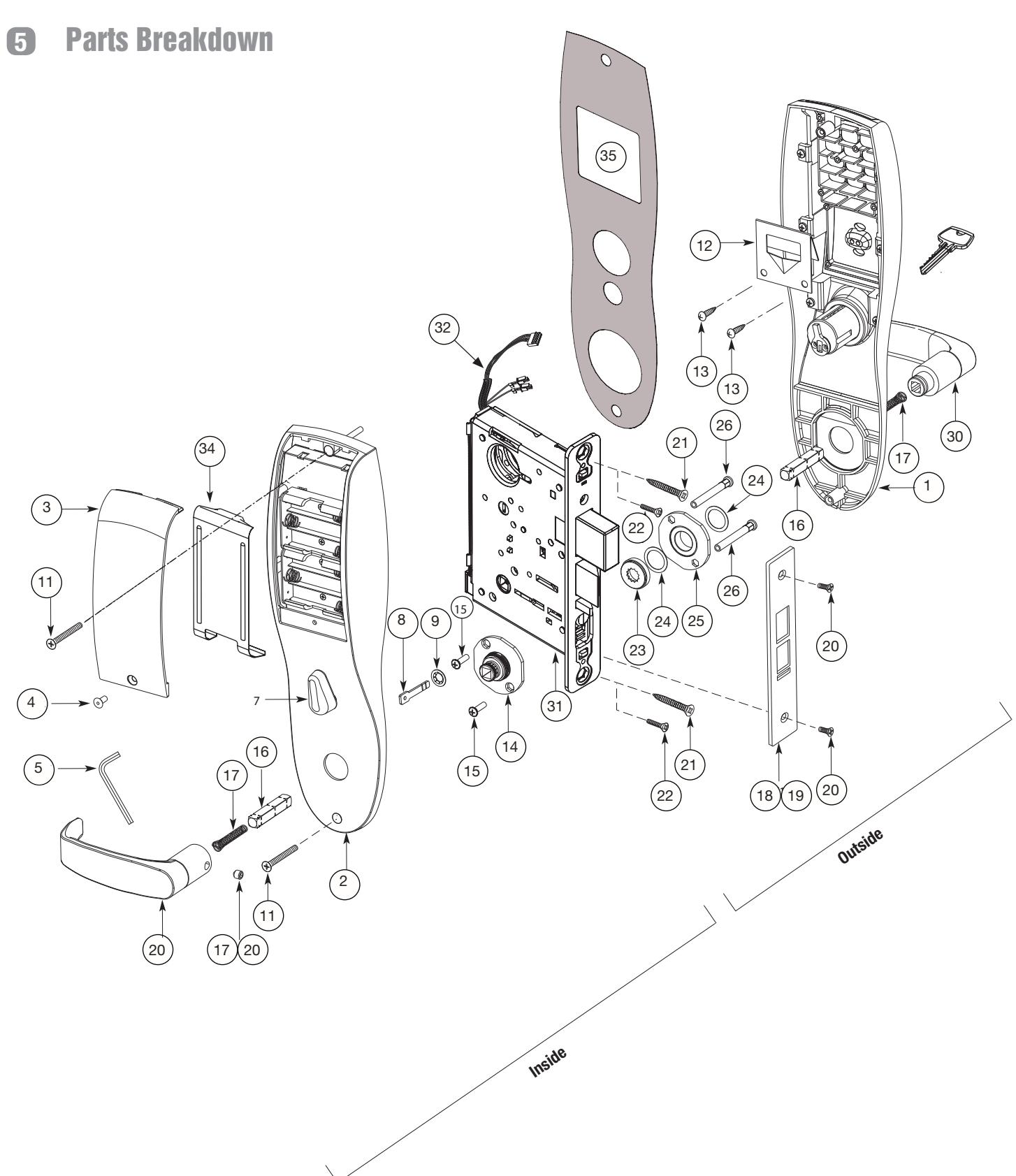
Parts Breakdown (Continued)
| ITEM | PART No. | DESCRIPTION | REQ'D |
|---|---|---|---|
| 1 | 82-4190 |
Outside Escutcheon with Cylinder Hole and Key Pad, or Key
Pad/Prox (G1-LU, G1-PK, G1-TU, G1-TP) |
1 |
| 82-4191 |
Outside Escutcheon without Cylinder Hole and Key Pad or Key
Pad/Prox (G1-LU, G1-PK, G1-TU, G1-TP) |
1 | |
| 82-4192 |
Outside Escutcheon with Cylinder Hole and Prox Only (G1-PA,
G1-TA) |
1 | |
| 82-4193 |
Outside Escutcheon without Cylinder Hole and Prox Only (G1-
PA, G1-TA) |
1 | |
| 82-0493 | Outside Escutcheon Housing Only without Cylinder Hole | 1 | |
| 82-0495 | Outside Escutcheon Housing Only with Cylinder Hole | 1 | |
| 52-2432 | Keypad/Proximity Bezel Assembly w/ Harness (LK) | 1 | |
| 52-2706 | Proximity Only Bezel Assembly with Harness (G1-PA, G1-TA) | 1 | |
| 52-2704 |
Key Pad/Proximity Bezel Assembly with Harness (G1-LU, G1-PK,
G1-TU, G1-TP) |
1 | |
| 2 | 82-3837 | Inside Escutcheon with Thumb Turn and 100 User Controller (LK) | 1 |
| 82-3838 |
Inside Escutcheon without Thumb Turn and 100 User Controller
(LK) |
1 | |
| 82-4182 |
Inside Escutcheon with Thumb Turn and 2000 User Controller
(G1-LU) |
1 | |
| 82-4183 |
Inside Escutcheon without Thumb Turn and 2000 User Controller
(G1-LU) |
1 | |
| 82-4184 |
Inside Escutcheon with Thumb Turn Prox/Key Pad Controller
(G1-PA, G1-PK) |
1 | |
| 82-4185 |
Inside Escutcheon without Thumb Turn Prox/Key Pad Cont.
(G1-PA, G1-PK) |
1 | |
| 82-4186 |
Inside Escutcheon with Thumb Turn & 2000 User Controller with
RF Technology (G1-TU) |
1 | |
| 82-4187 |
Inside Escutcheon without Thumb Turn & 2000 User Controller
with RF Technology (G1-TU) |
1 | |
| 82-4188 |
Inside Escutcheon with Thumb Turn & Keypad/Prox or Prox Only
Controller (G1-TA, G1-TP) |
1 | |
| 82-4189 |
Inside Escutcheon without Thumb Turn & Keypad Prox or Prox
Only Controller (G1-TA, G1-TP) |
1 | |
| 82-0492 | Inside Escutcheon Housing Only without Thumb Turn | 1 | |
| 82-0494 | Inside Escutcheon Housing Only with Thumb Turn | 1 | |
| 52-2440 | 100 (LK) User Key Pad Controller Assembly | 1 | |
| 52-2783 | 2000 (G1-LU) User Controller Assembly | 1 | |
| 52-2784 | 2000 User (G1-PA, G1-PK) Controller Assembly | 1 | |
| 52-2786 |
2000 User Keypad/Prox Controller Assembly with RF Technology
(G1-TA, G1-TP) |
1 | |
| 52-2785 |
2000 User Keypad Controller Assembly with RF Technology
(G1-TU) |
1 | |
| 3 | 52-0170 | Battery Cover | 1 |
| 52-2509 | Battery Cover – RF Technology (G1-TU,G1-TP, G1-TA) | 1 |
| ITEM | PART No. | DESCRIPTION | REQ'D |
|---|---|---|---|
| 4 | 01-1212 | Security Screw | 1 |
| 5 | 01-0297 | Security Tool | 1 |
| 7 | 82-0507 | Thumb Turn | 1 |
| 8 | 77-0772 | Spindle (Thumb Turn) | 1 |
| 9 | 01-0844 | Washer (Thumb Turn) | 1 |
| 10 | 01-0543 | Spring Grip Fastener (Thumb Turn) | 1 |
| 11 | 77-0168 | Through-bolts #8-32 x 1 7/8" Flat Head Screw | 2 |
| 12 | 52-0033 | Fire Stop Plate | 1 |
| 13 | 01-1500 |
Fire Stop Screws #8 x 1/2" Type "AB" Phillips Pan Head
Self Tap |
2 |
| 14 | 82-3088 | Inside Spindle Adapter & Plate Assembly | 1 |
| 15 | 01-1495 | Screw #8-32 x 1/2" | 2 |
| 16 | 82-0368 | Inside Spindle/Outside Spindle | 2 |
| 17 | 82-0347 | Inside Spring/Outside Spring | 2 |
| 18 | 82-0081 | Face Plate no Dead Bolt | 1 |
| 19 | 82-0084 | Face Plate with Dead Bolt | 1 |
| 20 | 01-1028 | Face Plate Screws Machine 8-32 x 1/4" | 2 |
| 21 | 01-2299 | Lock Body Screws/Wood Door #12 x 1 1/4" | 2 |
| 22 | 01-1019 | Lock Body Screws/Metal Door 12-24 x 1/2" | 2 |
| 23 | 82-0184 | Cap Nut | 1 |
| 24 | 01-0079 | Washer | 2 |
| 25 | 82-3082 | Plate Assembly | 1 |
| 26 | 81-0723 | Post | 2 |
| 27 | 01-1472 | Lever Handle Screw, A, E & F Lever | 1 |
| 28 | 01-1174 | Lever Handle Screw, B, J, L, P & W Lever | 1 |
| 29 | Reference Profile Series catalog for available lever handles | ||
| 30 | Reference Profile Series catalog for available lever handles | ||
| 31 | G1-8276-hand-finish | Lockbody Assembly with deadbolt & cylinder | 1 |
| G1-8277-hand-finish | Lockbody Assembly with deadbolt only (no cylinder) | ||
| G1-8278-hand-finish | Lockbody Assembly with cylinder only (no deadbolt) | ||
| G1-8279-hand-finish | Lockbody Assembly without deadbolt & without cylinder | ||
| 32 | 01-0803 | Battery Alkaline ("AA" cell - not shown) | 6 |
| 33 | 52-0253 | Battery Keeper | 1 |
| 52-0344 | Battery Keeper – RF Technology (G1-TU, G1-TP, G1-TA) | 1 | |
| 34 | 10-0649 | Gasket, weatherseal | 1 |
6 Installation Instructions
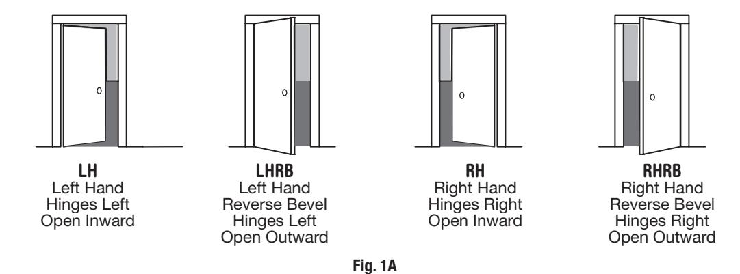
Step #1 – Verify Hand and Bevel of Door
A. Verify Hand and Bevel of Door
Stand on outside/locked side of door when determining the door hand
B. Prepare Door
Prep door according to Instruction Sheet A7457 and appropriate template: Manufacturer Door Template: 4533
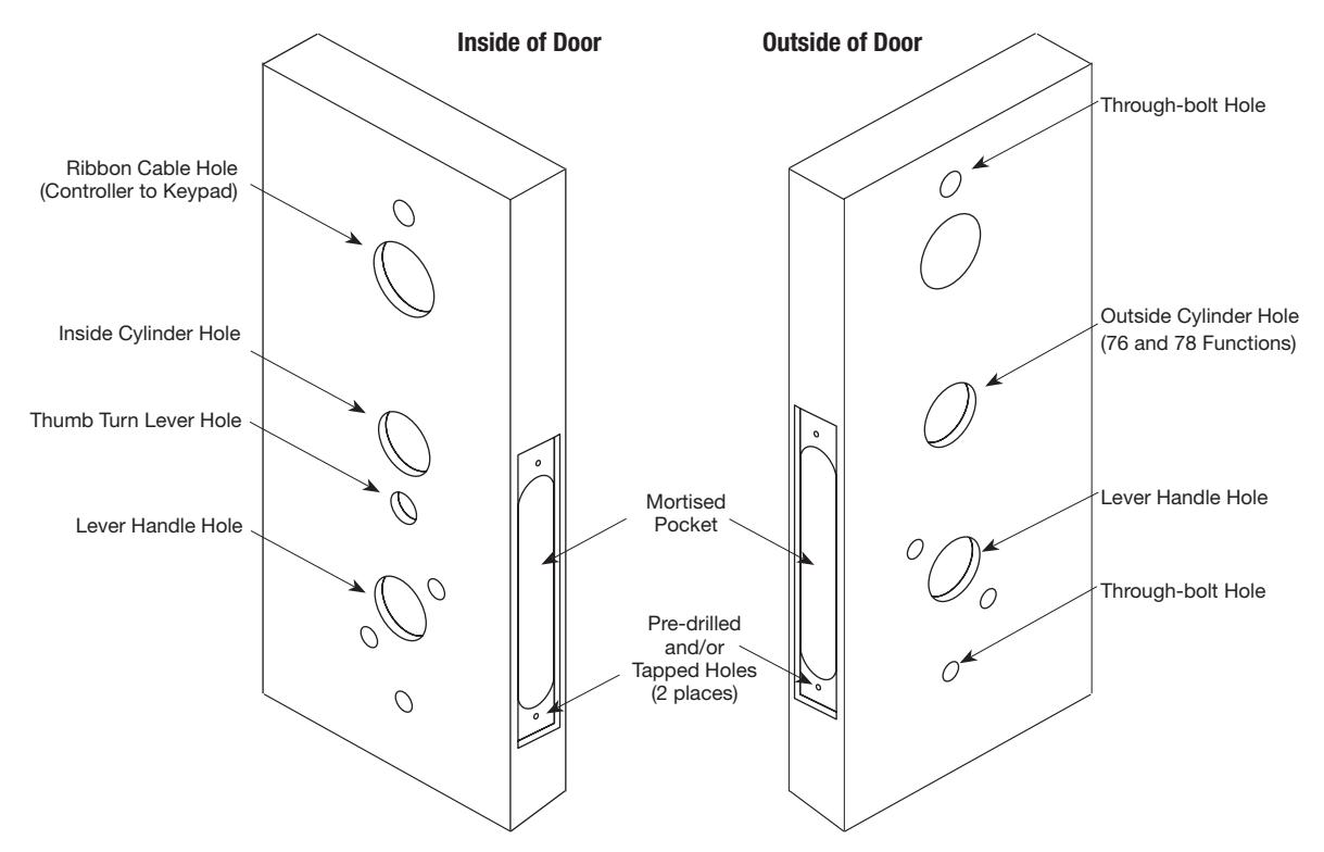
Fig. 1B Wood Door Preparation

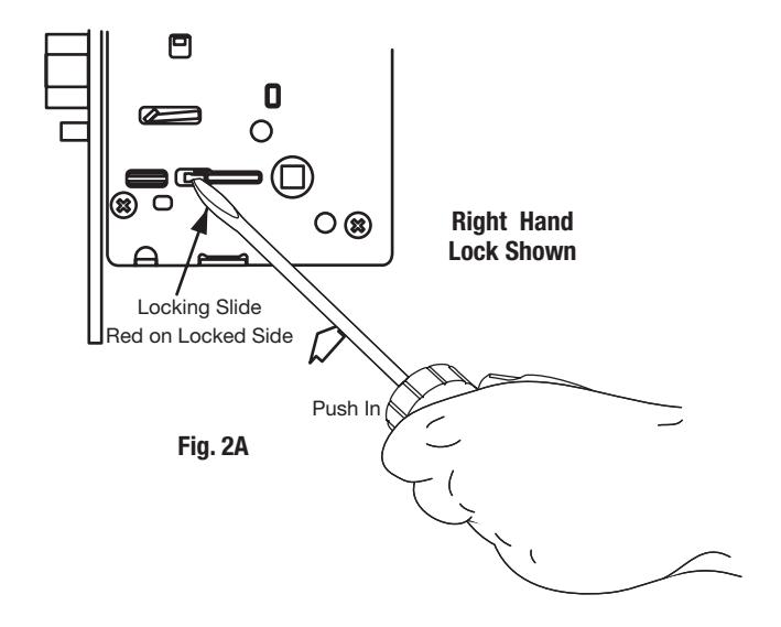
Step #2 – How to Change Hand of Lockbody
A. Reverse Lock Hand
Red surface of locking piece must face the outside/locked side of door. To rotate locking piece (Fig. 2A):
- 1. Position lock body with red surface of locking piece visible.
- 2. Insert blade type screwdriver into locking piece slot to rotate locking piece toward back of lock body.
- 3. Rotate the locking piece 180° until RED surface is on opposite side. Note: Red indicates locked side (outside).
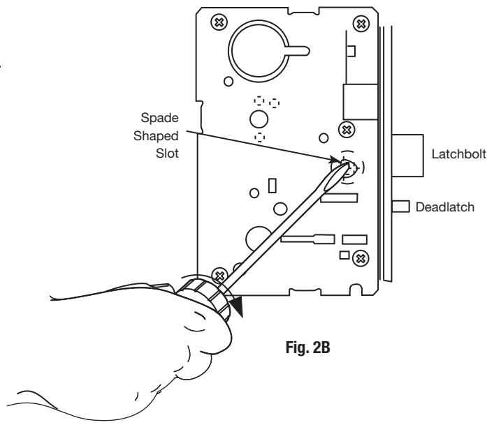
B. Reverse Latch Hand
Beveled surface of latchbolt must face strike (Fig. 2B). The deadlatch is self adjusting.
To change the hand of the latchbolt:
- 1. Insert the blade of a slotted screwdriver (>1/4") into the spade shape slot behind latch.
- 2. Rotate the screwdriver 90° to push latchbolt out until back of bolt clears lock case front.
- 3. Rotate latchbolt 180° until the latchbolt drops back into the lock body.
Note: Latch cannot be unscrewed.
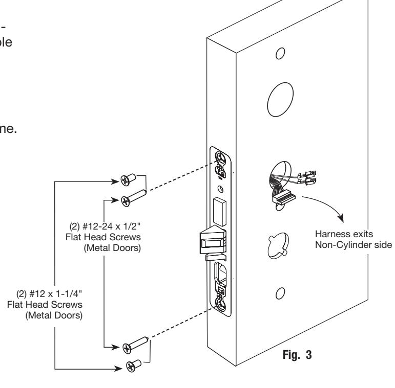
Step #3 – Install Lock Body
- 1. Insert lock body into mortised cutout by first feeding harness (6)-pin connector through cylinder hole on non-cylinder side followed by the two (2)-pin connectors (Fig. 3).
- 2. Hold lock body loosely in place with (2) lock body screws.
Note: Do not completely tighten screws at this time.
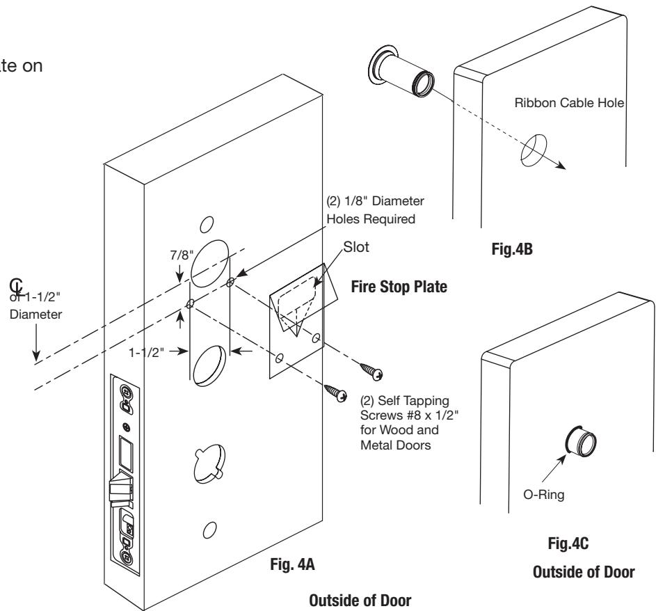
Step #4 – Exterior Door Options
A. Fire Stop Plate (P/N 53-0033)
Fire-rated doors require a fire stop plate on the outside of the door (Fig. 4A).
- 1. Drill (2) 1/8" x 1-1/4" deep holes in the door if not already present. Refer to template for fire-stop prep locations.
- 2. Attach with flap up and out using (2) #8 x 1/2" self-tapping screws for wood and metal doors.
B. Weather Conduit (P/N 52-2847)
Install weather conduit on NON FIRE-RATED exterior doors only.
- 1. Carefully insert the weather conduit into the ribbon cable hole on the inside of the door (Fig. 4B).
- 2. Place the O-ring around the weather conduit on the outside and up against the door (Fig. 4C).
Step #5 – Install Weatherseal Gasket (Exterior Doors)
- 1. Carefully remove the backing from the gasket.
-
2. Apply gasket to escutcheon:
- Starting in one place, press the adhesive side of the gasket firmly against the escutcheon.
- Work around the escutcheon, pressing the sticky side of the gasket firmly against the escutcheon edge.
- The gasket should be aligned so that all edges of the escutcheon are covered.

Note: The 43 cylinder may be used with or without a gasket.
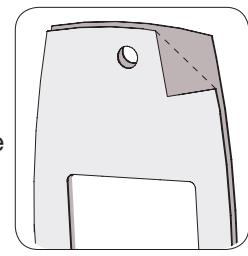
Fig. 5A
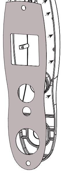
Fig. 5B
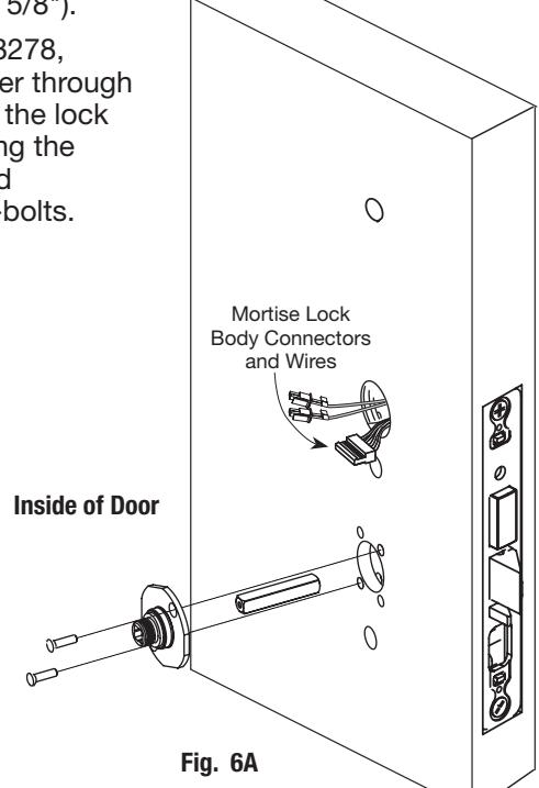
Step #6 – Install Outside Escutcheon and Lever Assembly
1A. For 12- fire rated doors : Feed ribbon cable with connector and ground wire from outside of door through weather seal gasket and fire stop plate (Fig. 6A).
Note: Install ribbon cable with cable exiting down
1B. For non-12- fire rated doors: Feed ribbon cable with connector and ground wire from outside of door through weather seal gasket (if used) and weather conduit (not shown).
Note: Install ribbon cable with cable exiting down, orienting with side marked 'TOP' facing up.
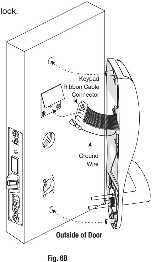
- 2. With outside lever horizontal, locate the outside escutcheon on the door, while directing the mounting posts through the door and lock body (Fig. 6B).
- 3. Make certain the lever spindle is properly engaged in lock.
5. Slide inside adapter and plate assembly over spindle
4. On the inside of the door, insert spindle into square hole of mortise lock.
and loosely secure with 2 through bolt screws (#8-32 x 5/8"). Note: For 8276 and 8278, loosely thread cylinder through escutcheon and into the lock body before tightening the lock case screws and escutcheon through-bolts.
Copyright © 2017, Sargent Manufacturing Company, an ASSA ABLOY Group company. All rights reserved. Reproductions in whole or in part without express written permission of Sargent Manufacturing Company is prohibited.
SARGENT
ASSA ABLOY
Step #7 – Inside Escutcheon Wire Connections
Images are shown without gasket.
If gasket is necessary, refer to Step #5.
Before the controller is attached to the door:
- Attach the reader assembly ribbon cable into the back of the controller assembly (side that faces towards the door when mounted (Fig. 7A).
- 2. Attach the ground wire to the bottom of the controller assembly (E1, Fig. 7A).
- 3. Connect the cable from the lock body to the bottom of the controller assembly (TB1, Fig. 7B).
If Hardwiring is required, go to "Hardwiring Options" on page 16.
Place extra wire inside door hole and/or outside escutcheon, being careful not to pinch wires. Connectors go on only one way.
Do not offset connectors, and make sure they are completely seated.
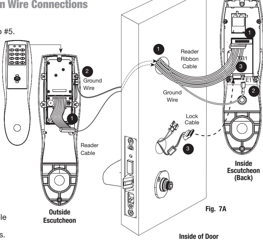
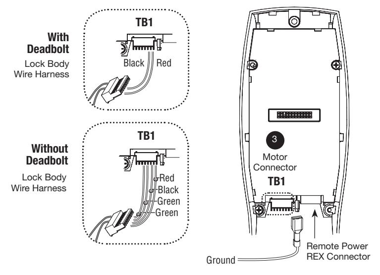
Fig. 7B

Step #7 – Inside Escutcheon Wire Connections (Continued)
Installation of Motor Harness and Inside Lever Monitor Switch
LH/LHR Lock Configuration
- For LH/LHR lock: Connect lock's two-pin connector with blue & yellow wires to adapter harness (as shown in Fig. 7C)
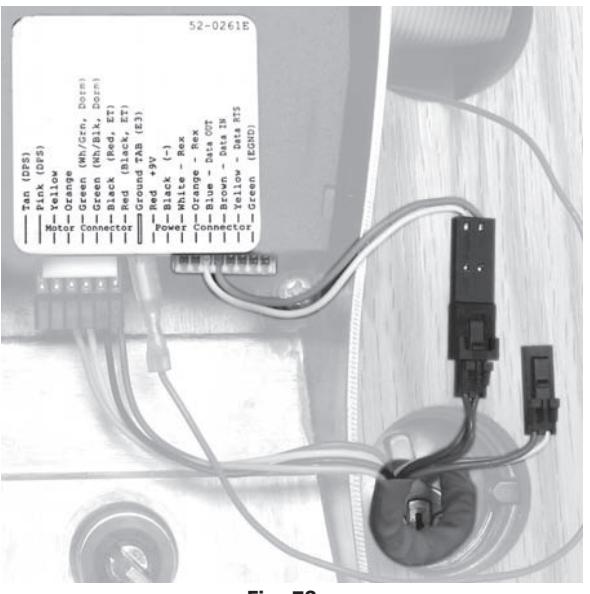
RH/RHR Lock Configuration
- For RH/RHR lock: Connect lock's two-pin connector with white & orange wires to adapter harness (as shown in Fig. 7D)
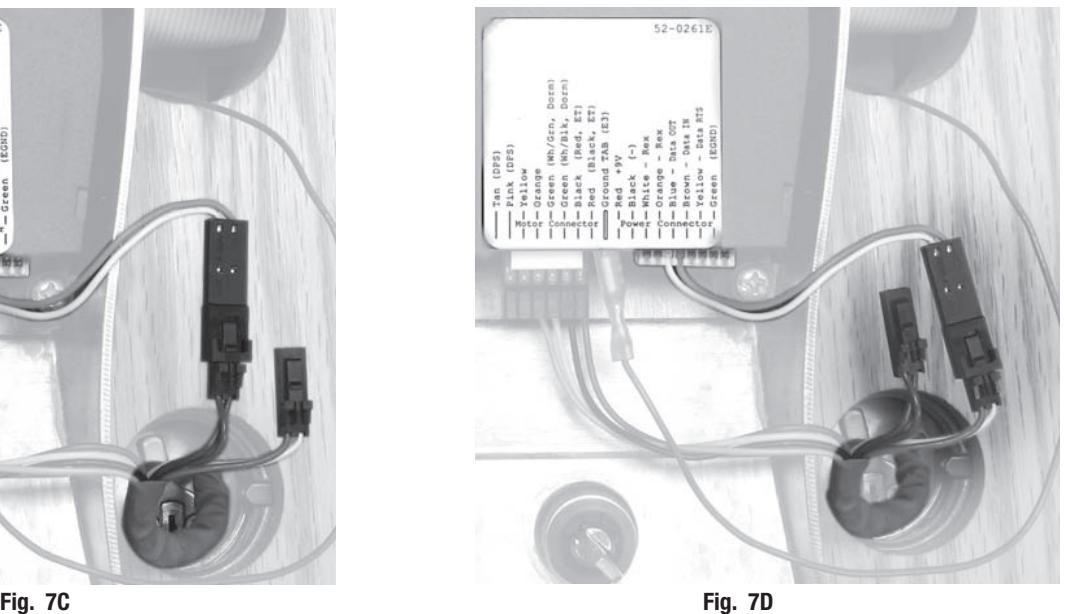
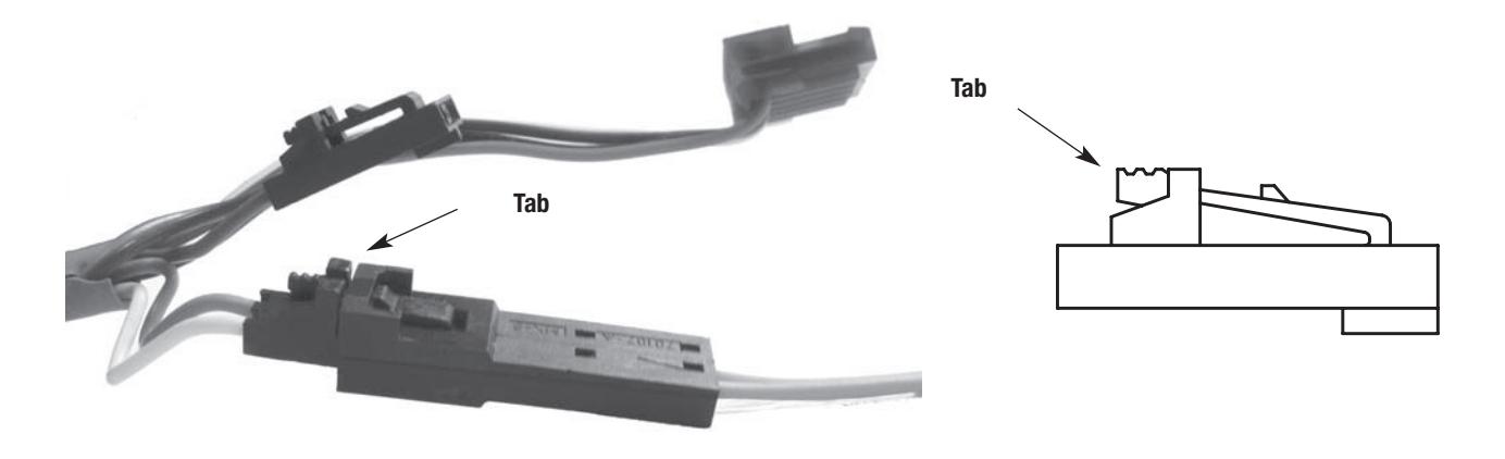
Note: To disconnect the two-pin connectors, press tab and pull connectors apart gently
Reproductions in whole or in part without express written permission of Sargent Manufacturing Company is prohibited.
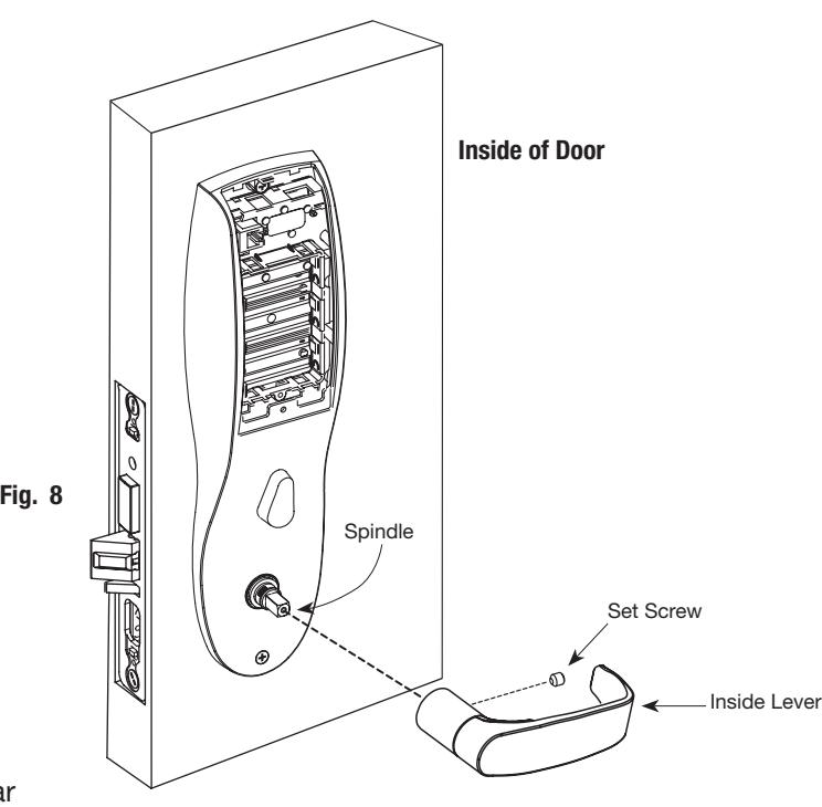
Step #8 – Inside Lever Installation
- 1. Slide lever handle onto spindle until fully seated (Fig. 8).
- 2. Insert #8-32 x 1-1/4" screws through inside escutcheon and thread into outside escutcheon.
- 3. Straighten escutcheons and tighten securely.
- 4. Tighten the set screw securely with 1/8" hex wrench.
Profile Series v.G1.5 Mortise Dorm Lock
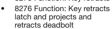
Step #9 – Install and Secure Cylinder
1. Slide cylinder through the spring and rosette/collar and screw into lock body, rotating the cylinder clockwise (Fig. 9A).
Cylinder should be flush with rosette/collar.
Note: The 43 cylinder may be used when installing this product with or without a gasket.
Note: SARGENT logo must be horizontal and on the top of the cylinder (Fig. 9B).
- 2. Secure the cylinder by tightening cylinder clamp screw located above the deadbolt using #2 Phillips screwdriver (Fig. 9C).
- 3. Using the key, test cylinder functions:
Step #11 – Attach Battery Keeper and Cover 1. Secure the inside escutcheon using two #8-32 screws through top and bottom of the escutcheon (Fig. 11). Thread into outside escutcheon. Note: For RF Technology versions (G1-TU, G1-TP, G1-TA), refer to "RF Technology Lock" section on page 14 to install through-bolt screws. 2. Straighten escutcheons and tighten securely, being careful to avoid pinching wires. 3. Attach inside cover to escutcheon making sure to line up tabs with retaining slots in cover. 4. Secure with security screw using security tool (P/N 01-0297) provided (Fig. 11). Inside of door Fig. 11 Battery Keeper Battery Cover Security Screw Security Tool 01-0297 (Included) #8-32 Screws #8-32 Screws
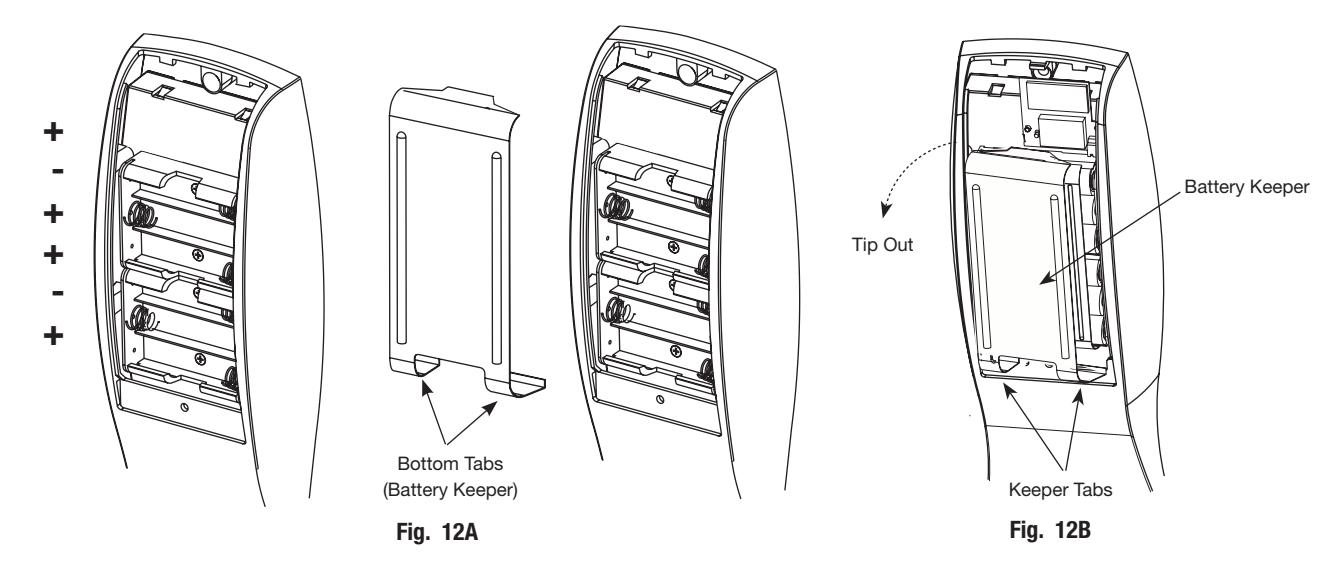
Step #12 – Install and Remove Batteries*
A. Install Batteries and Keeper
- 1. Place (6) "AA" batteries into the compartment, being careful to properly align polarity (Fig. 12A).
-
2. To install battery keeper, insert the tabs on the bottom of the keeper into the battery compartment slots and press the keeper tightly against batteries and inserting tabs into bottom slots.
- For RF technology, use RF Technology lock information "RF Technology Lock" in next section (7). IMPORTANT : * Do not install batteries if controller is powered by external power supply.
- Test for proper operation before closing door.
B. Remove Battery Keeper
To remove the battery keeper, pull the keeper away from the batteries (Fig. 12B).
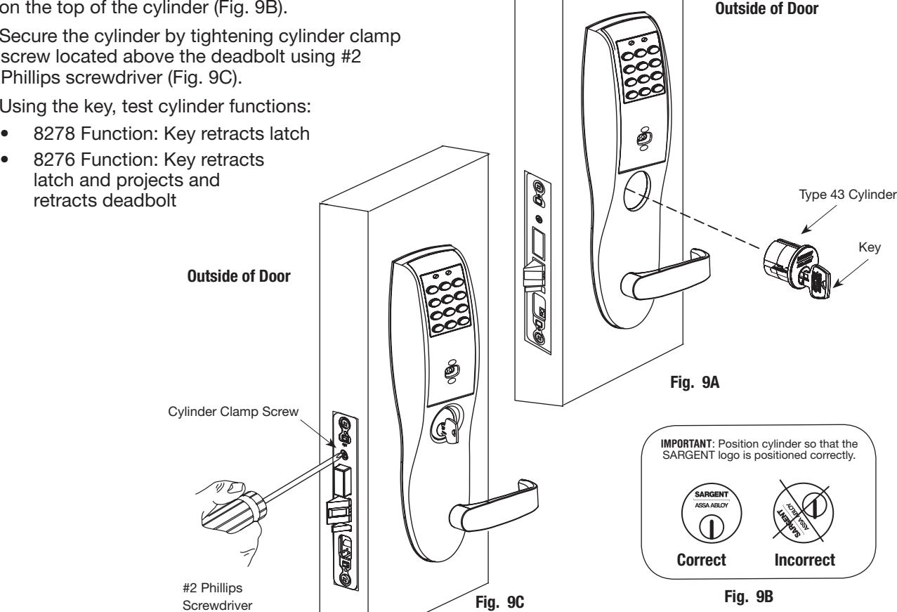
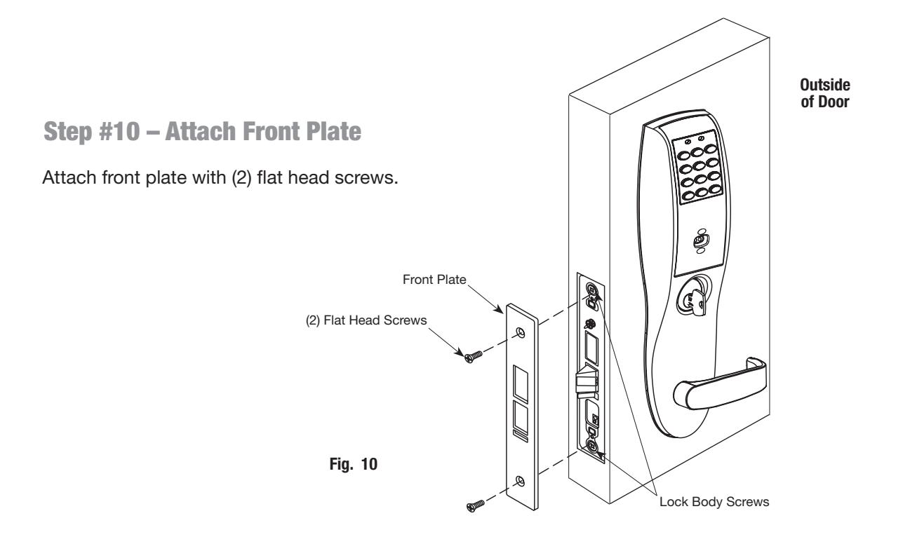
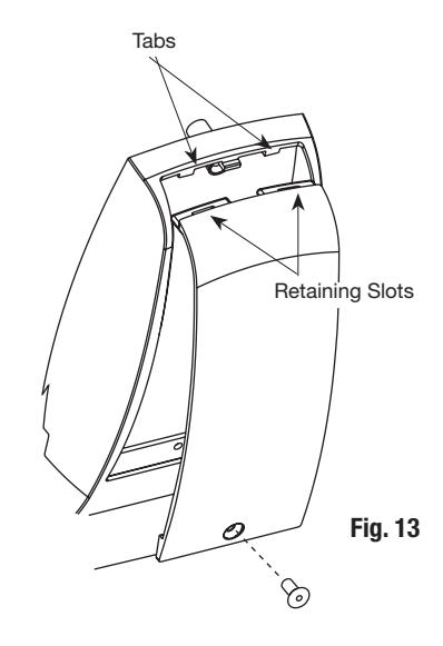
Step #13 – Install Inside Cover
- 1. Attach inside cover to escutcheon making sure to line up tabs with retaining slots in cover.
- 2. Secure with security screw using provided security tool (Fig. 13).
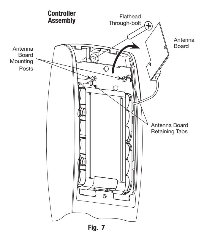
7 RF Technology Lock
Installation for the RF Technology Lock for G1-TU, G1-TA, G1-TP is, for the most part, installed as described in Section 6.
In addition:
The antenna board must be carefully moved to access the upper through-bolt screw.
Care should be taken to prevent damage to the antenna retaining tabs during this process (Fig. 7).
- 1. Press the two tabs away from the antenna board and lift the board off the mounting posts.
- 2. Insert the flat head through-bolt and secure the escutcheon in place.
- 3. After tightening the top through-bolt, replace the antenna board by placing it on the mounting posts and pressing into the retaining tabs.

8 Hardwiring Options
Hardwiring options include one or a combination of Forced/Propped Door, Hard Power and/or Remote Unlock (REX). Refer to the examples on the following pages:
- 1. Forced/Propped Door Option (DM-).
- 2. Hard Power and Remote Unlock (91-).
- 3. Hard Power and Remote Unlock (-91), with Forced Propped Door (DM-).
Important
- 1. Caution: Disconnect all input power before beginning installation to prevent electrical shock and equipment damage.
- 2. Installer must be a trained, experienced service person.
- 3. All wiring must comply with applicable local electrical codes, ordinances and regulations.
Installation Notes
- 1. With new applications, an ElectroLynx® door harness with 8 and 4 pin connectors will be pre-installed inside door by ASSA ABLOY door manufacturer when specified during ordering process.
- 2. Wiring to pigtail harness is per facility wiring requirement. ElectroLynx® connector terminations and wire colors all match.
- 3. If door does not have an ElectroLynx® type door harness, cut connectors off product and hard-wire, or consult factory for appropriate mating harness.
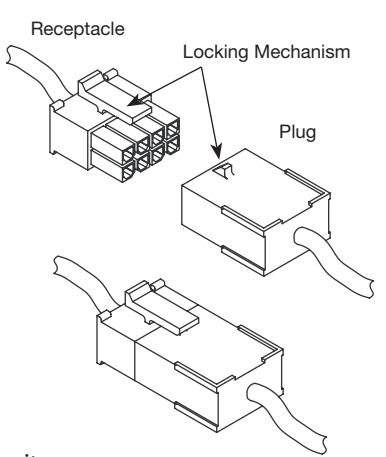
ElectroLynx® Connector System Notes
The system is designed to be installation friendly with connectors from the electric hinge through the door to the rail. The only wiring required is to the loose wires on the pigtail harness assembly on the frame side of the electric hinge.
IMPORTANT :
The plug and receptacle connectors are designed to mate and lock together as shown in the figure. Plug the connectors into each other with the locking mechanism aligned as indicated.
Do NOT force connectors on any other way.
ElectroLynx®
As part of their promise to provide innovative, fast and effective, and higher security solutions to their customers, ASSA ABLOY Group companies offer ElectroLynx, a universal quick-connect system that simplifies the electrification of the door opening. ElectroLynx® is a registered trademark of ASSA ABLOY, Inc.
A
ElectroLynx Lock Wire Connections
Door Position Switch (DPS)
Install the SARGENT 3287 Door Status Switch according to instructions included in the kit.
Wire the 3287 Door Status Switch to the ElectroLynx frame harness and to the door status wires:
- 1. Connect the common wire of the switch to the common wire of the harness.
- 2. Connect the normally open wire of the switch to the door position wire of the harness.
Note: The third wire (normally closed) of the 3287 Door Status Switch is not used for this type of system.
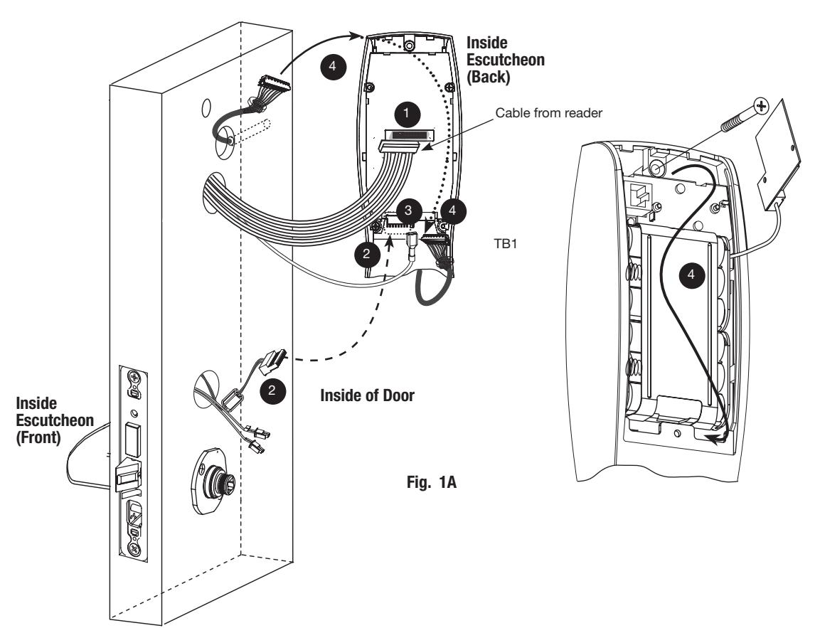
Before the controller is attached to the door (Fig. 1A):
- 1. Attach the reader cable to the controller.
- 2. Attach the connector from the lock into the bottom of the circuit board (TB2), Fig. 1A. 2
- 3. Plug the ground wire into the bottom of the controller assembly. 3
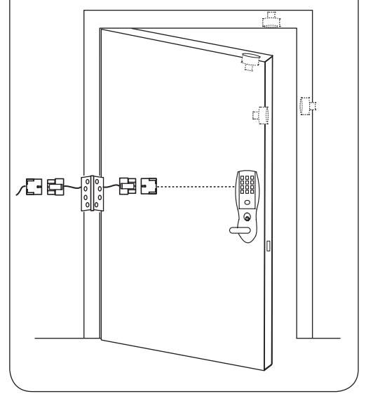
Fig. 1
4. Route the connector from the raceway through the top opening between the controller and the escutcheon, along the battery keeper, back under the bottom opening between the controller and escutcheon and attach at the bottom of the controller. 4
Note: Connectors go on only one way.
Do not offset connectors and make sure they are completely seated.
11/30/17
SARGENT ASSA ABLOY
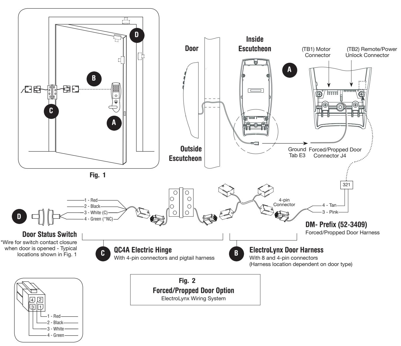
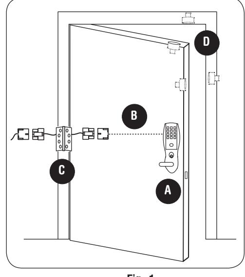
Option #1 – Forced / Propped Door (DM-)
Installation
-
1. ElectroLynx® System Wiring Instructions (Fig. 1 and Fig. 2):
- a. Look for the mating part on ASSA ABLOY doors and frames.
- b. Plug in all connectors during product installation (Fig. 2).
- c. Hard wire door status switch as shown
-
2. Non-ElectroLynx® System Wiring Instructions (Fig. 1 and Fig. 2):
- a. Cut the 4-pin connector off the Forced/Propped harness and hard wire to non-ElectroLynx® two conductor door harness.
- b. DM- requires two conductors.
- c. Hard wire door harness to power transfer device.
- d. Hard wire door status switch to power transfer device.
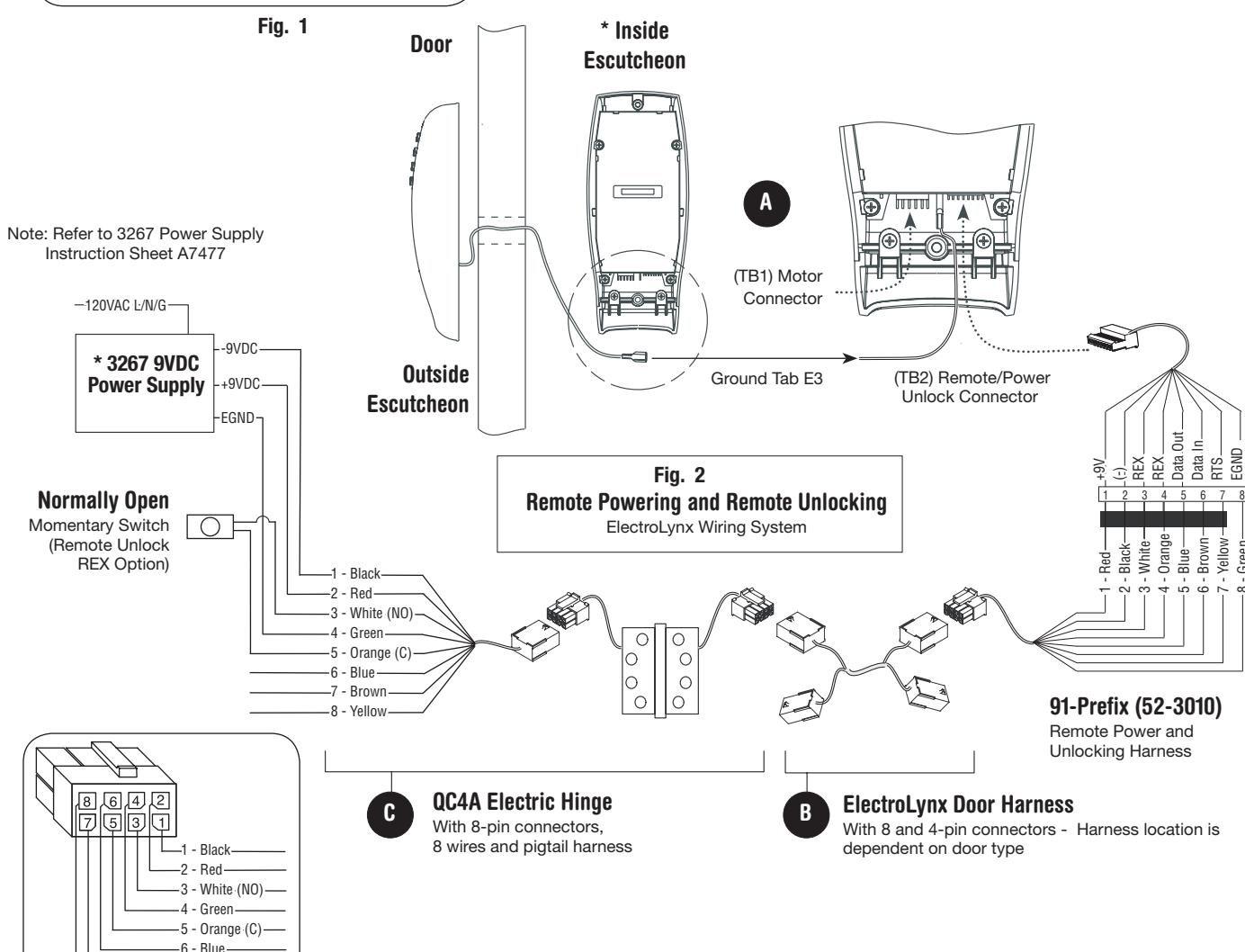
Option #2 – Remote Power and Remote Unlock (91-)
Installation
-
1. ElectroLynx® System Wiring Instructions (Fig. 1 and Fig. 2):
- a. Look for the mating part on ASSA ABLOY doors and frames.
- b. Plug in all connectors during product installation (Fig. 2).
- c. Hard wire hard power and/or remote unlock (REX) (Fig. 2).
-
2. Non-ElectroLynx® System Wiring Instructions (Fig. 1 and Fig. 2):
- a. Cut the 8-pin connector off the Remote Power/Unlock harness and hard wire to non-ElectroLynx® door harness.
- b. Remote power requires three conductors and remote unlock requires two conductors.
- c. Hard wire door harness to power transfer device.
-
d. Hard wire door status switch to power transfer device.
- *IMPORTANT: (6) "AA" batteries MUST be removed from controller when using 3267 power supply.
-7 - Brown -8 - Yellow
ASSA ABLOY
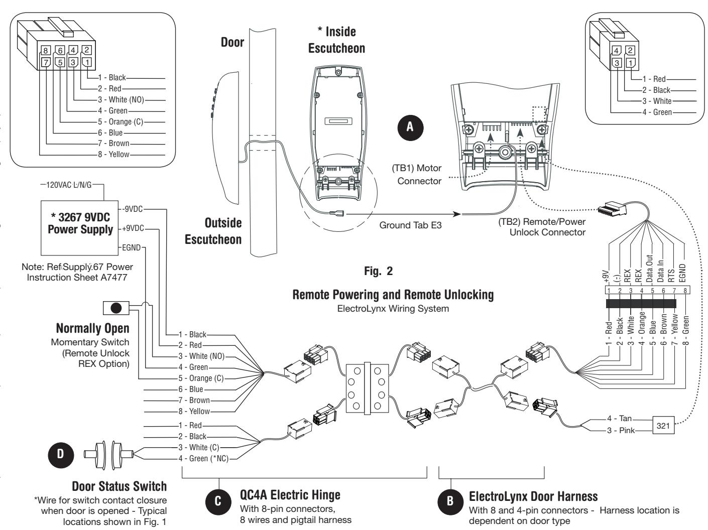
Option #3 – Hard Power/Remote Unlock (91-) Combined With Forced/Propped Door (DM-)
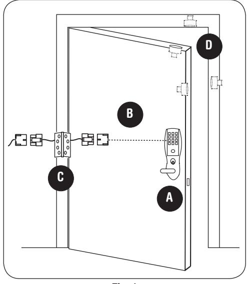
Fig. 1
Installation
-
1. ElectroLynx® System Wiring Instructions (Fig. 1 and Fig. 2):
- a. Look for the mating part on ASSA ABLOY doors and frames.
- b. Plug in all connectors during product installation (Fig. 2).
- c. Hard wire hard power and/or remote unlock (REX) (Fig. 2).
-
2. Non-ElectroLynx® System Wiring Instructions (Fig. 1 and Fig. 2):
- a. Cut the 8 and 4-pin connectors off the Remote Power/Unlock harness and hard wire to non-ElectroLynx® door harness.
- b. Remote power requires three conductors; and remote unlock and DM- require two conductors.
- c. Hard wire door harness to power transfer device.
-
d. Hard wire door status switch to power transfer device.
- *IMPORTANT: (6) "AA" batteries MUST be removed from controller when using 3267 power supply.

9 Operational Check
For devices with cylinders, insert key into cylinder and rotate.
Check to see if:
-
1. The key retracts the latch.
- Key should rotate freely.
- Key should extend and retract the deadbolt (if applicable).
-
2. The inside lever retracts latchbolt.
- Thumbturn should extend and retract the deadbolt (if applicable).
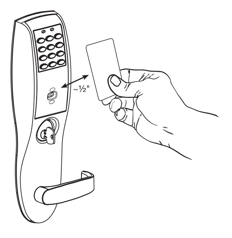
- 3. Enter 1234* to unlock outside lever handle and retract latch and deadbolt if provided).
Note: If the lock is prox only (G1-PA) or RF Technology with Prox (G1-TA), refer to keypad programming instruction manual A7857.

SARGENT Manufacturing Company 100 Sargent Drive New Haven, CT 06511 USA 800-810-WIRE (9473) • www.sargentlock.com
Founded in the early 1800s, SARGENT® is a market leader in locksets, cylinders, door closers, exit devices, electro-mechanical products and access control systems for new construction, renovation, and replacement applications. The company's customer base includes commercial construction, institutional, and industrial markets.
Copyright © 2017, Sargent Manufacturing Company, an ASSA ABLOY Group company. All rights reserved. Reproduction in whole or in part without the express written permission of Sargent Manufacturing Company is prohibited.