Profile Series v.G1 Exit Device Installation Instructions
Open the original PDF document
View PDFInstallation Instructions For Profile Series v.G1 Exit Device
A7757C
Table of Contents
| Page | ||
|---|---|---|
| 1 | Warning | |
| 2 |
General Description
1 |
|
| 3 |
Specifications
1 |
|
| 4 |
Features
1 |
|
| 5 |
Parts Breakdown
2-5 |
|
| 6 |
Installation Instructions–Rim Type Device
6-9 |
|
| 7 | Installation Instructions–Mortise Type Device10-13 | |
| 8 |
Operational Check
14 |
|
| 9 | Installation of the RF Technology Lock (G1-TU, G1-TA, G1-TP)14 |
1 Warning Warning: Changes or modifications to this unit not expressly approved by the party responsible for compliance could void the user's authority to operate the equipment.
This device complies with Part 15 of the FCC Rules. Operation is subject to the following two conditions: (1) this device may not cause harmful interference, and (2) this device must accept any interference received, including interference that may cause undesired operation.
Note: This equipment has been tested and found to comply with the limits for a Class B digital device, pursuant to Part 15 of the FCC Rules. These limits are designed to provide reasonable protection against harmful interference in a residential installation. This equipment generates, uses and can radiate radio frequency energy and if not installed and used in accordance with the instructions, may cause harmful interference to radio communications. However, there is no guarantee that the interference will not occur in a particular installation. If this equipment does cause harmful interference to radio or television reception, which can be determined by turning the equipment off and on, the user is encouraged to try to correct the interference by one or more of the following measures:
- Reorient or relocate the receiving antenna
- Increase the separation between the equipment and receiver
- Connect the equipment into an outlet on a circuit different from that to which the receiver is connected
- Consult the dealer or an experienced TV technician for help
This Class B digital apparatus complies with Canadian ICES-003.
Cet appareil numérique de la classe B est conforme avec la norme NMB-003 du Canada.

Warning ! To comply with "Fire Listed" doors, the batteries must be replaced with alkaline batteries only.
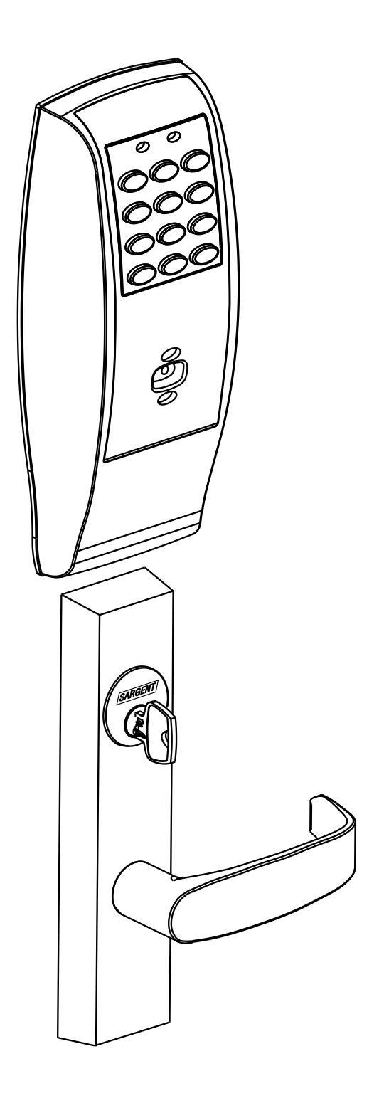
2 General Description
The SARGENT Profile Series v. G1 Rim/Mortise Exit Device is designed for areas which require stand alone authorized entry. It is a self-contained microprocessorcontrolled keypad with non-volatile memory. The keypad will hold a total of 100 (LK)/2000 (GI-LU, GI-PK, GI-PA, G1-TU, G1-TP, G1-TA) different user codes. User locations "01" & "02" are utilized for Master and Supervisory Codes, respectively.
This product is operated by six (6) "AA" alkaline batteries. SARGENT exit devices locks are designed with high quality components to provide high security, performance and durability.

Items Supplied with Exit Device
Items included in your 8877 and 8977 Series Exit Device carton:
- Outside Escutcheon with Keypad
- Outside motorized Trim Assembly
- Exit Device
- Mortise cylinder for 8977
- Rim cylinder for 8877
- Inside Escutcheon with Circuit Board and Battery Pack
- 6 "AA" alkaline batteries
- Screw Pack
Items included in your 8878 and 8978 Series Exit Device carton:
- Outside Escutcheon with Keypad
- Outside Motorized Trim Assembly
- Exit Device
- Inside Escutcheon with Circuit Board and Battery Pack
- 6 "AA" alkaline batteries
- Screw Pack
Specifications 3
Profile Series Rim Exit
- Latch 3/4" throw, stainless steel
- Outside motor driven "ET" lever controlled by keypad
- Push bar retracts latch from inside
- Fire stop provided on all lever handle designs
- Profile Series exit devices furnished for 1-3/4" doors
- UL Listed
- Accepts all SARGENT rim cylinders (8877 only)
- Key retracts latch (8877 only)
- Available in "ET" lever handle designs only
Profile Series Mortise Exit
- Latch 3/4" throw, anti-friction, brass
- Outside motor driven "ET" lever controlled by keypad
- Push bar retracts latch from inside
- Fire stop provided on all lever handle designs
- Profile Series exit devices furnished for 1-3/4" doors
- UL Listed
- Accepts all SARGENT mortise cylinders (8977 only)
- Key retracts latch (8977 only)
- Available in "ET" lever handle designs only
Features 4
- Low battery alert 4 chirps after code entry
- External remote "request to enter" connector
- Master, Emergency or Supervisory code will unlock door when low battery has expired
- Programming done at keypad or with a PDA using SofLink™ Plus software and a PC (software required for G1-PA & G1-TA)
- Entry of three wrong User Codes disables all codes for ten seconds. Yellow LED on solid
- Last 15 transactions can be output to portable printer via infrared link (LK Only)
- Last 2000 (Except LK) transactions can be output to PC using a PDA and SofLink™ Plus software
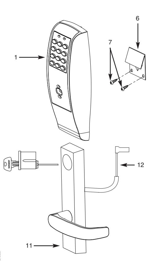
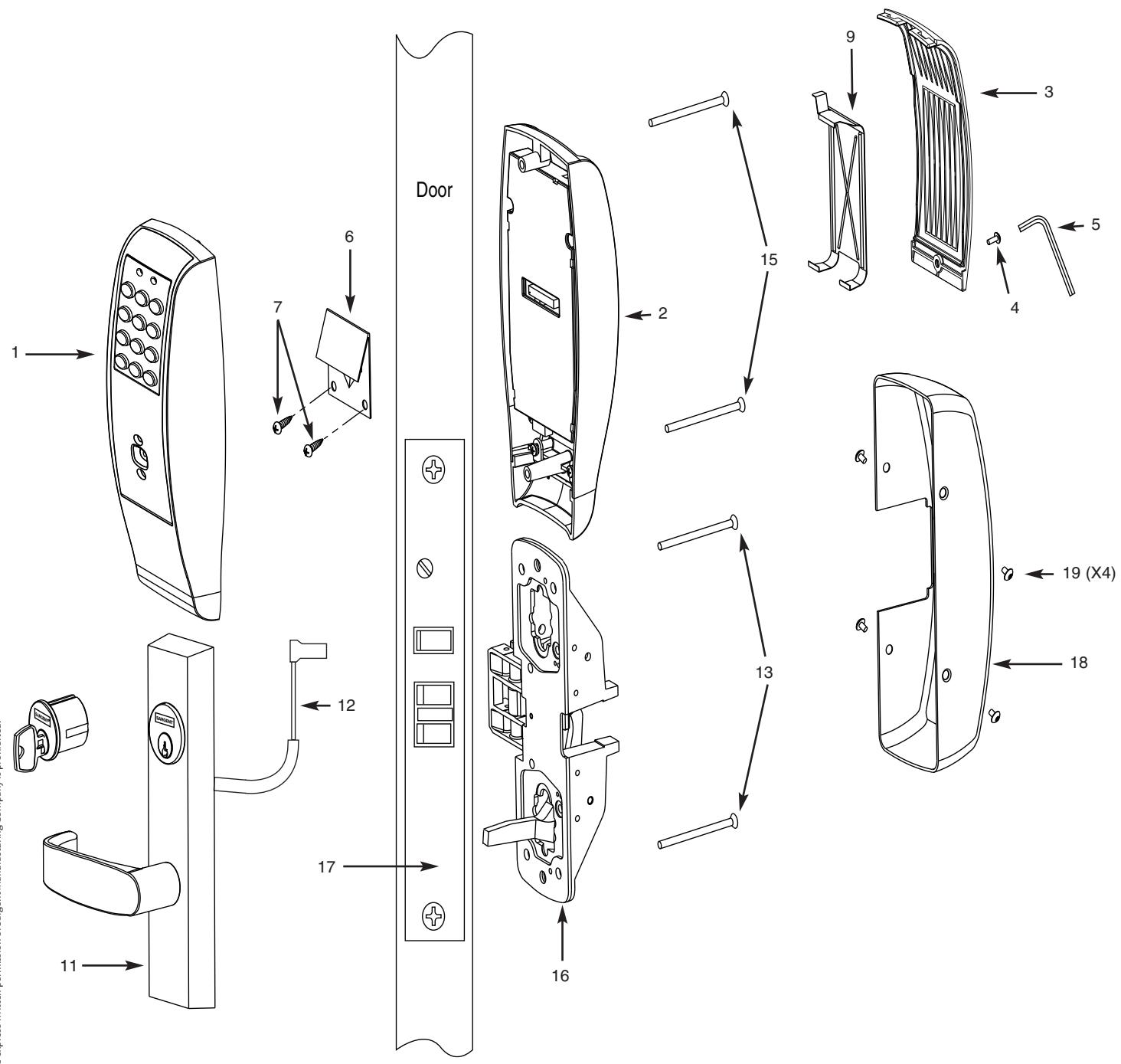
Parts Breakdown 8877/8878 x ET x Lever Design Profile Series Rim Exit Device


| ITEM | PART No. | DESCRIPTION | REQ'D |
|---|---|---|---|
| 1 | 52-2839 | Outside Escutcheon (Prox Only) Assembly (G1-PA, G1-TA) | 1 |
| 52-2474 | Outside Escutcheon (Keypad Only) Assembly (LK) | ||
| 1 | 52-2838 | Outside Escutcheon (Keypad/Prox) Assembly (G1-LU, G1-PK, G1-TU, G1-TP) | 1 |
| 52-2704 | Key Pad and Proximity Assembly (G1-LU, G1-PK, G1-TU, G1-TP) | 1 | |
| 52-2432 | Keypad/Proximity Bezel Assembly w/ Harness (LK) | 1 | |
| 52-2706 | Proximity Only Assembly (G1-PA, G1-TA) | 1 | |
| 68-1397 | Outside Escutcheon Housing Only | 1 | |
| 52-0176 | Outside Escutcheon End Cap | 1 | |
| 2 | 52-2460 | Inside Escutcheon Assembly with 100 User Controller (LK) | 1 |
| 2 | 52-2833 | Inside Escutcheon Assembly with 2000 User Controller (G1-LU) | 1 |
| 2 | 52-2834 | Inside Escutcheon Assembly with Prox/Key Pad Controller (G1-PA, G1-PK) | 1 |
| 52-2836 |
Inside Escutcheon Assembly (Keypad Only)
with RF Technology Controller (G1-TU) |
||
| 52-2835 |
Inside Escutcheon Assembly (Keypad/Prox or Prox Only)
with RF Technology Controller (G1-TA, G1-TP) |
||
| 68-1396 | Inside Escutcheon Housing Only | 1 | |
| 52-0175 | Inside Escutcheon End Cap Only | 1 | |
| 52-2441 | 100 User Controller Assembly (LK) | 1 | |
| 52-2783 | 2000 User Controller Assembly (G1-LU) | 1 | |
| 52-2784 | 2000 User Controller Assembly (G1-PA, G1-PK) | 1 | |
| 52-2786 | 2000 User (Keypad/Prox or Prox Only) Controller Assembly w/ RF Technology (G1-TA, G1-TP) | ||
| 52-2785 | 2000 User (Keypad Only) Controller Assembly w/ RF Technology (G1-TU) | ||
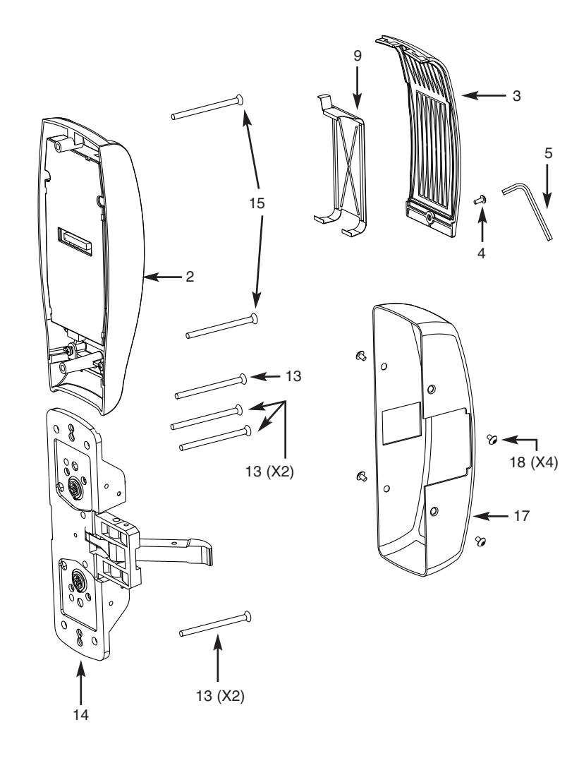
| 3 | 52-0170 | Battery Cover | 1 |
| 52-2309 | Battery Cover – RF Technology (G1-TU,G1-TP, G1-TA) | ||
| 4 | 01-1212 | Security Screw | 1 |
| 5 | 01-0297 | Security Tool | 1 |
| 6 | 52-0033 | Fire Stop Plate | 1 |
| 7 | 01-1500 | Fire Stop Screws #8 x 1/2" Type "AB" Phillips Pan Head Self Tap | 2 |
| 01-0803 | Battery Alkaline ("AA" Cell) | 6 | |
| 9 | 52-0253 | Battery Keeper | 1 |
| 52-0344 | Battery Keeper – RF Technology (G1-TU, G1-TP, G1-TA) | ||
| 10 | 52-2425 | Screw Pack (Includes item numbers 5, 6, 7, 15) | 1 |
| 11 | Consult Factory | Motorized ET Lever Trim | 1 |
| 12 | Consult Factory | Motor and Harness Assembly | 1 |
| 13 | 01-4451 | ET Through-bolts | 2 |
| 14 | 13-0074 | Cylinder Retaining Screws | 2 |
| 15 | 77-0685 | Escutcheon Through-bolts | 2 |
| 16 | 68-4261 | Center Case Assembly LHRB & RHRB (Std.) | 1 |
| 68-4263 | Center Case Assembly LHRB (12-) & RHRB (12-) | 1 | |
| 17 | 68-0406 | Chassis Cover | 1 |
| 18 | 97-0052 | Chassis Cover Screws | 4 |
Parts Breakdown 8977/8978 x ET x Lever Design Profile Series Mortise Exit Device

| ITEM | PART No. | DESCRIPTION | REQ'D |
|---|---|---|---|
| 1 | 52-2839 | Outside Escutcheon (Prox Only) Assembly (G1-PA, G1-TA) | 1 |
| 1 | 52-2838 | Outside Escutcheon (Keypad/Prox) Assembly (LK, G1-LU, G1-PK, G1-TU, G1-TP) | 1 |
| 52-2432 | Keypad/Proximity Bezel Assembly w/ Harness (LK) | 1 | |
| 52-2704 | Key Pad and Proximity Assembly (LK, G1-LU, G1-PK) | 1 | |
| 52-2706 | Proximity Assembly (G1-PA, G1-TA) | 1 | |
| 68-1397 | Outside Escutcheon Housing Only | 1 | |
| 52-0176 | Outside Escutcheon End Cap Only | 1 | |
| 2 | 52-2460 | Inside Escutcheon Assembly with 100 User Controller (LK) | 1 |
| 2 | 52-2833 | Inside Escutcheon Assembly with 2000 User Controller (G1-LU) | 1 |
| 2 | 52-2834 | Inside Escutcheon Assembly with Prox/Key Pad Controller (G1-PA, G1-PK) | 1 |
| 52-2836 |
Inside Escutcheon Assembly (Keypad Only)
with RF Technology Controller (G1-TU) |
||
| 52-2835 |
Inside Escutcheon Assembly (Keypad/Prox or Prox Only)
with RF Technology Controller (G1-TA, G1-TP) |
||
| 68-1396 | Inside Escutcheon Housing Only | 1 | |
| 52-0175 | Inside Escutcheon End Cap Only | 1 | |
| 52-2441 | Enclosure (LK) Assembly | 1 | |
| 52-2783 | Enclosure (G1-LU) Assembly | 1 | |
| 52-2784 | Key Pad/Proximity Only Controller (G1-PA, G1-PK) Assembly | 1 | |
| 52-2786 | 2000 User (Keypad/Prox or Prox Only) Controller Assembly (G1-TA, G1-TP) | ||
| 52-2785 | 2000 User (Keypad Only) Controller Assembly (G1-TU) | ||
| 01-0803 | Battery Alkaline ("AA" Cell) | 6 | |
| 3 | 52-0170 | Battery Cover | 1 |
| 52-2509 | Battery Cover – RF Technology (G1-TU,G1-TP, G1-TA) | ||
| 4 | 01-1212 | Security Screw | 1 |
| 5 | 01-0297 | Security Tool | 1 |
| 6 | 52-0033 | Fire Stop Plate | 1 |
| 7 | 01-1500 | Fire Stop Screws #8 x 1/2" Type "AB" Phillips Pan Head Self Tap | 2 |
| 9 | 52-0253 | Battery Keeper | 1 |
| 52-0344 | Battery Keeper – RF Technology (G1-TU, G1-TP, G1-TA) | ||
| 10 | 52-2425 | Screw Pack (Includes item numbers 5, 6, 7, 15) | 1 |
| 11 | Consult Factory | Motorized ET Lever Trim | 1 |
| 12 | Consult Factory | Motor and Harness Assembly | 1 |
| 13 | 01-4451 | ET Through-bolts | 2 |
| 15 | 77-0685 | Escutcheon Through-bolts | 2 |
| 16 | 68-2172 | Center Case Assembly LHRB (Standard and 12-) | 1 |
| 16 | 68-2173 | Center Case Assembly RHRB (Standard and 12-) | 1 |
| 17 | 99-2401 | Mortise Lock LHRB | 1 |
| 17 | 99-2402 | Mortise Lock RHRB | 1 |
| 18 | 68-0407 | Chassis Cover | 1 |
| 19 | 97-0052 | Chassis Cover Screws | 4 |
Installation Instructions for Rim Type Exit Device 8877/8878 6
IMPORTANT: BEFORE STARTING
- • This device is non handed
- • Door should be fitted and hung
- • Verify box label for size of exit device, function and hand
Step #1 – Exit Hardware & Door Prep
- 1. If using a mullion, install in frame.
- 2. Prep door according to Exit installation instructions A6770 and template 4640 (metal and wood doors).
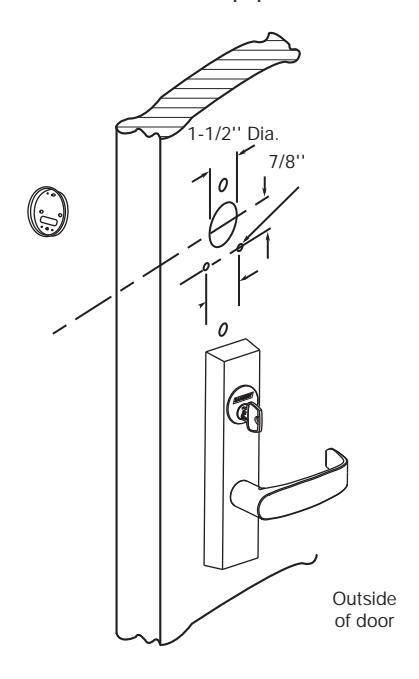
Step #2 – Installation of Outside Trim, Exit Chassis and Cylinder
A. Outside Trim
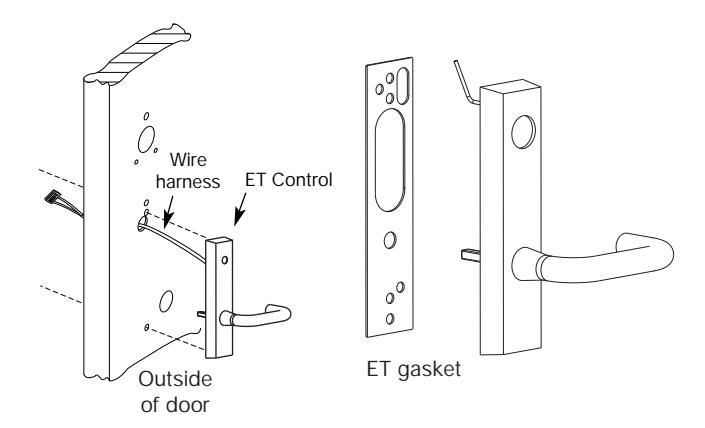
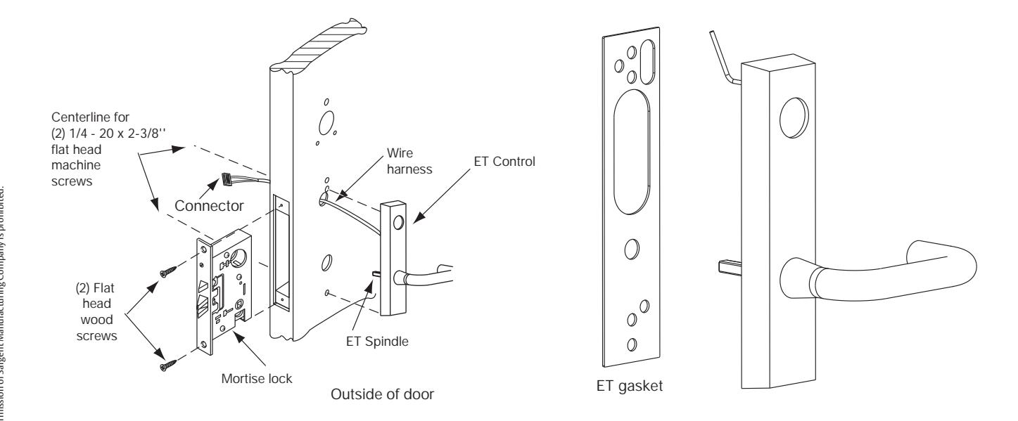
- 1. For exterior applications "ET" gasket (52-0263) should be used to seal between "ET" escutcheon and outside door surface
- 2. Route harness through under cut of cylinder hole and out to other side of door
- 3. Place "ET" control onto door
C. Cylinder Installation
NOTE: For devices without cylinder, go to Step D2.
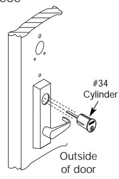
- 1. Insert cylinder into "ET" control
- 2. Mate cylinder tailpiece into hub of exit device chassis
- 3. Make sure "ET" harness is clear of cylinder and cylinder tailpiece
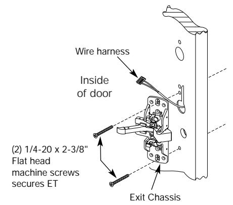
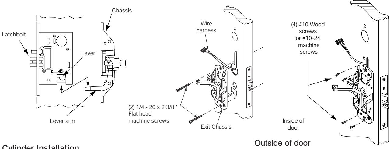
B.Inside Trim
- 1. Route "ET" harness along track cutout for wood doors and access hole for metal doors
- 2. Mount exit chassis carefully. DO NOT PINCH HARNESS WIRES
- 3. "ET" spindle will engage into the hub of exit device chassis
- 4. Secure chassis and "ET" with (2) 1/4 -20 x 2-3/8" flat head machine screws
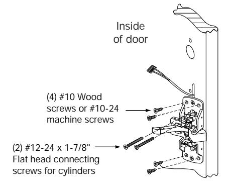
D. Securing Cylinder
- 1. Secure cylinder to exit chassis using (2) #12-24 x 1-7/8" connecting screws
- 2. Fasten exit chassis to door using (4) #10 wood screws or #10-24 machine screws
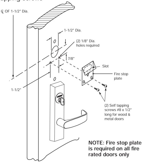
Installation Instructions (Continued) Step #3 – Attach Fire Stop Plate
NOTE: Required for 12- Fire Rated doors only
- 1. Drill (2) 1/8" diameter holes if the door is not supplied with them
- 2. Secure fire stop plate to door with (2) #8 x 1/2" self tapping screws
SARGENT ASSA ABLOY
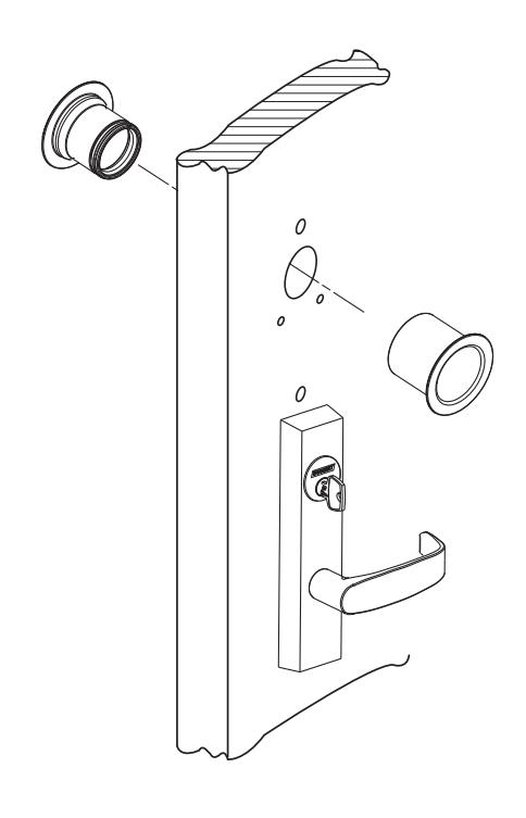
Non Fire Rated Exterior Doors-Install Weather Conduit (P/N 52-2847) as shown below
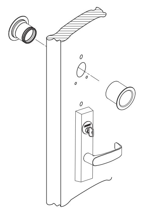
Step #4 – Installation of Outside Escutcheon
Insert connector and wires
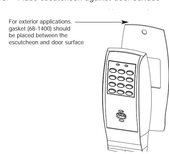
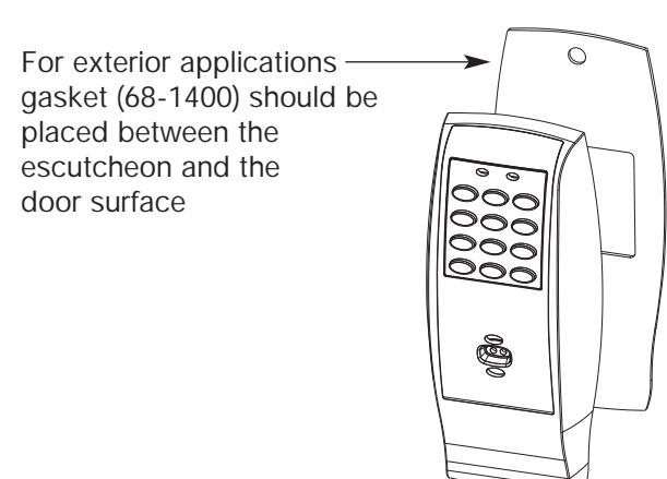
- 1. For exterior applications gasket (68-1400) should be used to seal between escutcheon and outside door surface
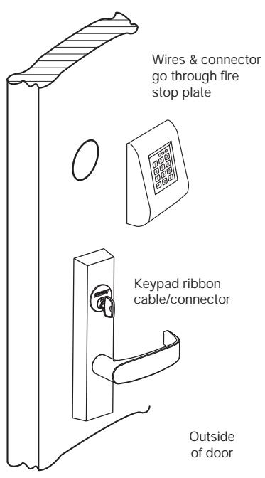
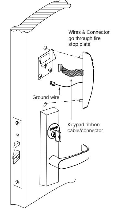
- 2a. For 12- fire rated devices feed keypad ribbon cable/connector from outside of door through gasket then fire stop plate
- 2b. For non-12- exit devices, feed keypad ribbon cable/connector through gasket then conduit hole in door
- 3. Place escutcheon against door surface
Rim Installation Instructions (Continued) Step #5 Installation of Inside Escutcheon

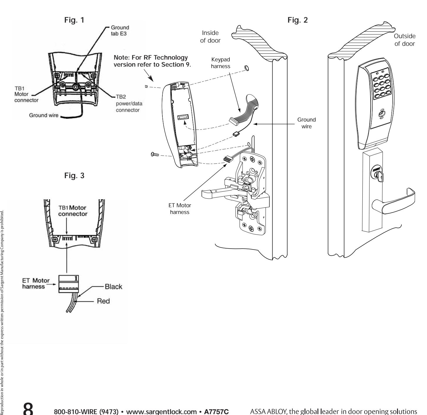
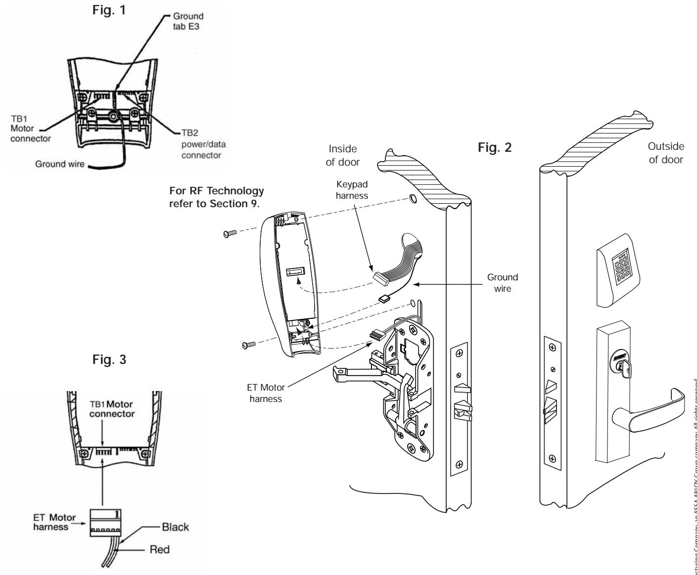
- 1. Connect ground wire to terminal E3 (Fig. 1), keypad harness to controller (Fig. 2), and ET motor harness to motor connector (Fig. 3).
- 2. Place extra wire inside door hole and/or outside escutcheon being careful not to pinch wires.
- 3. Connectors go on only one way, do not offset connector and be sure they are completely seated.
- 4. Insert #8-32 x 1-1/4" screws through inside escutcheon and thread into outside escutcheon. Straighten escutcheons and tighten securely.
Note : For RF Technology versions (G1-TU, G1-TP, G1-TA) refer to Section 9 to install through bolt screws.
Rim Installation Instructions (Continued)
SARGENT ASSA ABLOY
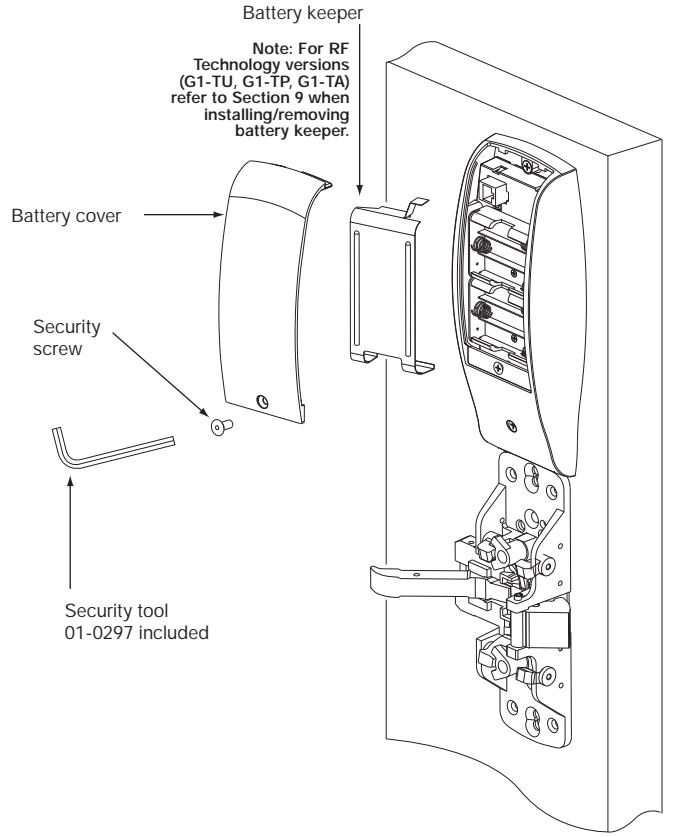
Fig. 4
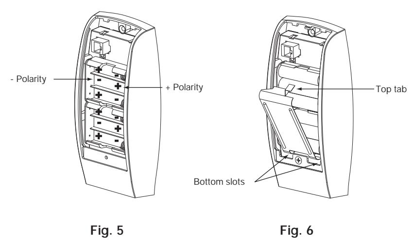
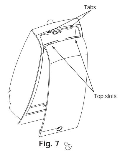
- 1. Place (6) "AA" batteries into the compartment, being careful to align polarity properly (Fig. 5).
- Install battery keeper clip by inserting tabs into bottom slots first (Fig. 6). To remove keeper, pull on top tab. For RF Technology version refer to Section 9.
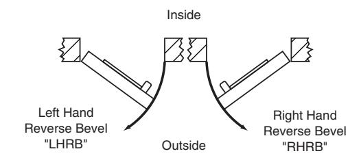
- 3. Attach battery cover to inside escutcheon, making sure to line up tabs with retaining slots in battery cover. Secure with security screw (Fig. 7).
Step #6 Rail Assembly
Attach rail assembly according to exit installation instructions A6770

Installation Instructions for Mortise Type Exit Device 8977/8978

IMPORTANT: BEFORE STARTING
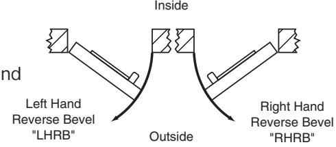
- Check hand of door this device is not reversible
- Door should be fitted and hung Verify box label for size of exit device, function and hand
Step #1 - Exit Hardware & Door Prep
Prep door according to Exit installation instructions A6705 and template 4641 (metal and wood doors).
Step #2 - Install Outside Trim, Exit Chassis and Cylinder
A. Outside Trim
- 1. Slide mortise lock into door and securely fasten with (2) flat head screws
- 2. For exterior applications gasket (52-0263) should be used to seal between "ET" escutcheon and outside door surface
- 3. Route "ET" harness through wire cutout and out other side of door
- 4. Place "ET" control on door with spindle inserted through mortise lock
Mortise Installation Instructions (Continued)
Step #2 – Install Outside Trim, Exit Chassis and Cylinder
B. Exit Chassis:
- 1. Route "ET" harness along track cutout for wood doors and access hole for metal doors
- 2. Mount exit chassis carefully. Do not pinch harness wires
- 3. Position exit chassis on door with lever arm under rear section of mortise lock
- 4. Using (2) 1/4-20 x 2-3/8" flat head screws attach chassis to "ET" control
- 5. Fasten exit chassis to door using (4) #10 wood screws or #10-24 machine screws
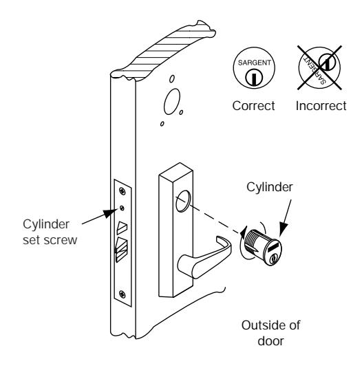
C. Cylinder Installation
NOTE: For devices without cylinders, skip this section.
- 1. Back cylinder set screw out of mortise lock
- 2. Insert cylinder through "ET" control and thread into mortise lock until cylinder is flush with "ET"
- 3. Tighten cylinder set screw
Mortise Installation Instructions (Continued) Step #3 – Attach Fire Stop Plate
NOTE: Required for 12- Fire Rated doors only
- 1. Drill (2) 1/8" diameter holes if the door is not supplied with them
- 2. Secure fire stop plate to door with (2) #8 x 1/2" self tapping screws

Non Fire Rated Exterior Doors-Install Weather Conduit (P/N 52-2847) as shown below
Step #4 - Installation of Outside Escutcheon
A. Insert Wires and Connector
- 1. For exterior applications gasket (68-1400) should be used to seal between escutcheon and outside door surface
- 2. For 12- fire rated devices feed keypad ribbon cable/connector from outside of door through gasket then fire stop plate
- 3. For non-12- exit devices, feed connector and wires through gasket then hole in door
- 4. Place escutcheon against door surface
Mortise Installation Instructions (Continued)
ASSA ABLOY
Step #5 - Installation of Inside Escutcheon
- 1. Connect ground wire to terminal E3 (Fig. 1), keypad harness to controller (Fig. 2), and ET motor harness to motor connector (Fig. 3).
- 2. Place extra wire inside door hole and/or outside escutcheon being careful not to pinch wires.
- 3. Connectors go on only one way, do not offset connector and be sure they are completely seated.
- 4. Insert #8-32 x 1-1/4" screws through inside escutcheon and thread into outside escutcheon. Straighten escutcheons and tighten securely.
NOTE: For RF Technology versions (G1-TU, G1-TP, G1-TA) refer to Section 9 to install through bolt screws.
5. Install batteries and cover according to instructions on page 9.
Step #6 - Rail Assembly
Attach rail assembly according to Exit installation instructions A6705
8 Operational Check
- 1. For devices without cylinder go to step 4
- 2. For devices with cylinders, insert key into cylinder and rotate
- 3. The key will retract the latch, the key should rotate freely
- 4. Depress inside rail to retract latch
- 5. Enter 1234* to unlock outside lever handle and retract latch
-
6. If Prox only (G1-PA) or RF Technology with Prox (G1-TA)
- refer to keypad programming instructions (A7716)
Key/Cylinder, Code Verification
9 Installation of the RF Technology Lock
The RF Technology Lock (G1-TU, G1-TA, G1-TP) is installed as described in sections 1-8 with the following exceptions:
- Installation of the top through-bolt screw
- · Removal process for the battery keeper
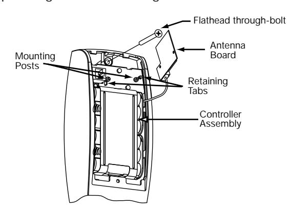
A. Installation of the top through-bolt screw:
The antenna board must be carefully moved to access the upper through-bolt screw. Care should be taken to prevent damage to the antenna retaining tabs during this process.
Press the two tabs away from the antenna board and lift the board off the mounting posts. Insert the flat head through-bolt and secure the escutcheon in place. After tightening the top through-bolt, replace the antenna board by placing it on the mounting posts and pressing into the retaining tabs.
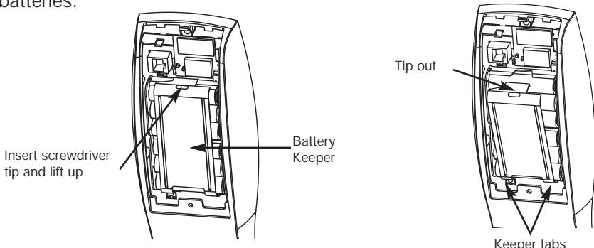
B. Removal procedure for the Battery Keeper:
To remove the battery keeper, a flat bladed screwdriver or similar tool must be used.
Insert the screwdriver into the slot at the top of the battery keeper, lift up and pull the top of the keeper away from the batteries.
To install, insert the tabs on the bottom of the keeper into the battery compartment slots and press the keeper tightly against batteries.