Profile Series Mortise Lock With Studio Collection Levers
Open the original PDF document
View PDFLevers from the Studio Collection
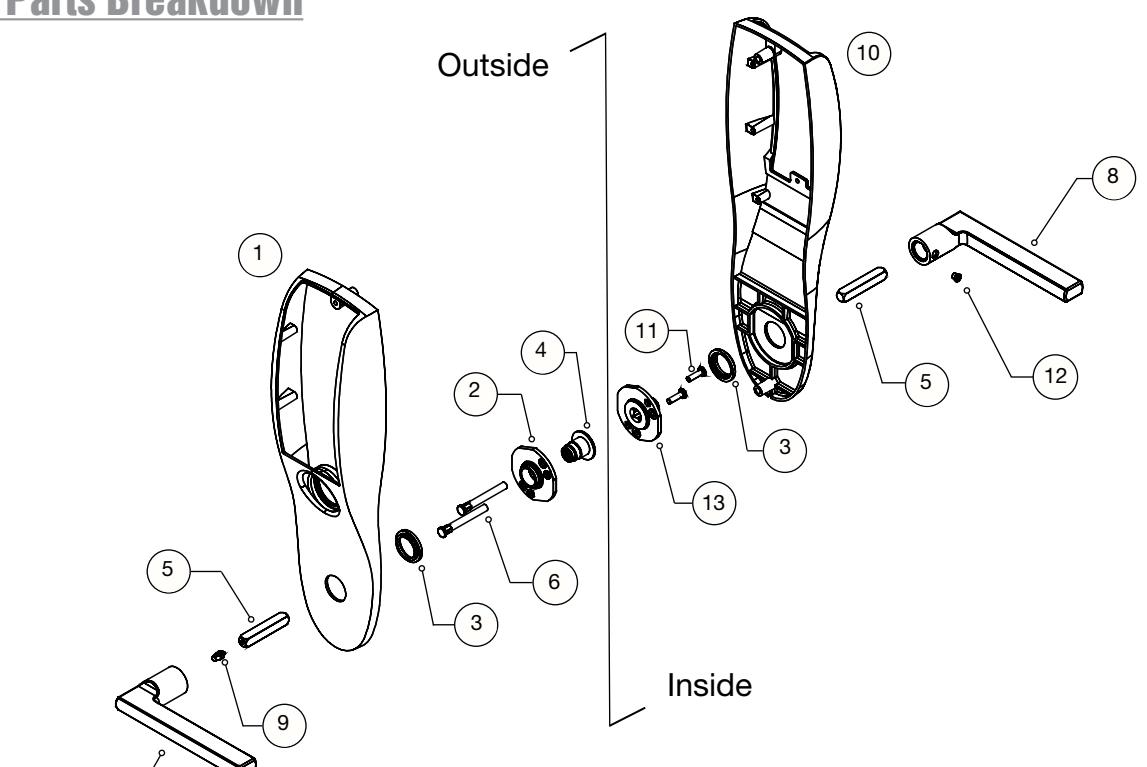
1 - Parts Breakdown
| Description | Part No. | Qty. | |
|---|---|---|---|
| 1 | Outside Escutcheon - w/ cylinder (cylinder not shown) | - | 1 |
| 2 | Adapter & plate assembly | 82-4576 | 1 |
| 3 | Trim insert | 82-1321 | 2 |
| 4 | Bushing (outside) | 82-0691 | 1 |
| 5 | Spindle | 82-0368 | 2 |
| 6 | Mounting post | 81-0723 | 2 |
| 7 | Lever, blank - Style "MD" shown | Consult factory | 1 |
| 8 | Lever, blank - Style "MD" shown | 1 | |
| 9 | Spindle anchor | 82-0614 | 1 |
| 10 | Inside escutcheon | - | 1 |
| 11 | Machine screw (#8-32 x 5/8") | 01-1495 | 2 |
| 12 | Locking screw | 82-1038 | 1 |
| 13 | Adapter, plate & bushing assembly (inside) | 82-4677 | 1 |

2 - Install Outside Lever
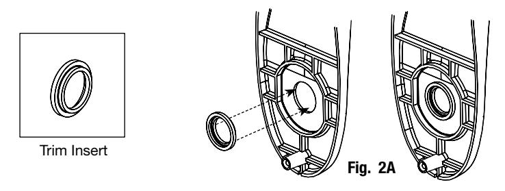
A. Place trim insert in escutcheon as shown in Figure 2A.
B. Assemble bushing, mounting plate and mounting posts as shown in Figure 2B.
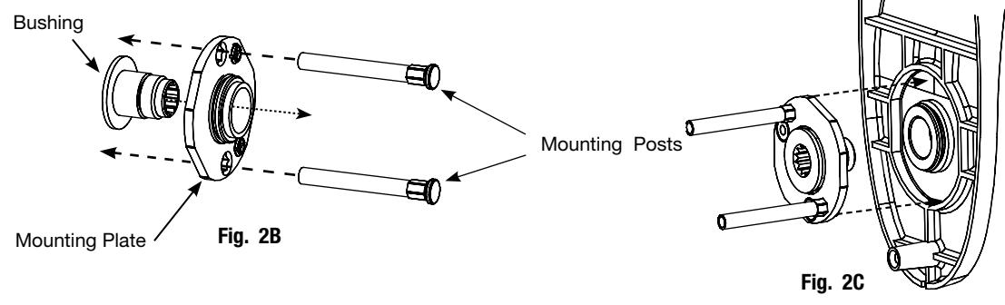
- C. Place assembly in outside escutcheon as shown in Figure 2C.
- D. Thread outside lever to bushing (Fig. 2D), rotating clockwise until at proper position*.
- E. Insert spindle through bushing into lever (Fig. 2E).
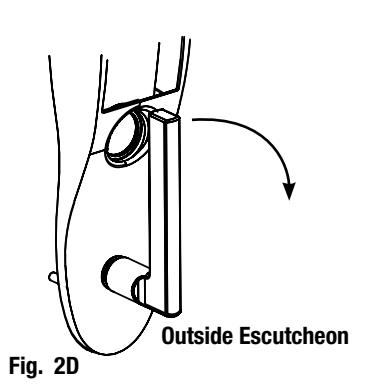
IMPORTANT: Use caution when threading outside lever to bushing. Lever should not come in contact with the surface of the escutcheon.
Overtightening the lever can damage the surface of the outside escutcheon.
*The lever should be pointing toward the hinge side (away from the latch).
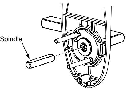
Fig. 2E
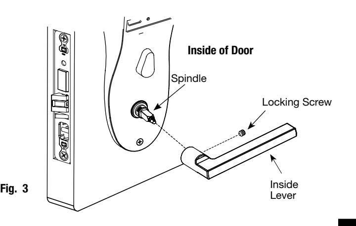
3 - Install Inside Lever
- A. Insert spindle. Slide lever onto spindle until fully seated (Fig. 3).
- B. Tighten the locking screw securely with TR-20 torx wrench.
06/06/12
Copyright © 2012 Sargent Manufacturing Company, an ASSA ABLOY Group company. All rights reserved. Reproductions in whole or in part without express written permission of Sargent Manufacturing Company is prohibited.