Phi Apex 2000 Series Touchbar Exit Device Trim Sell Sheet
Open the original PDF document
View PDF

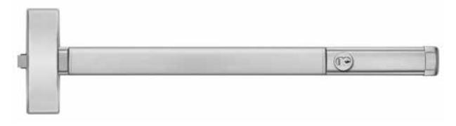
Apex 2000 Series
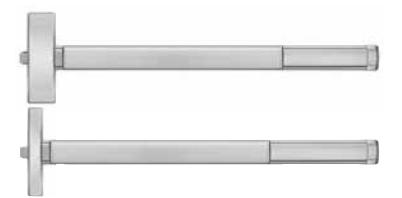
Touchbar Exit Devices

TABLE OF CONTENTS
|
Wide Stile Exit Devices & Trims
Rim Devices4, 5 |
|
|---|---|
| Surface Vertical Rod Devices6, 7 | |
| Mortise Devices8, 9 | |
| Wood Door Concealed Vertical Rod Devices14, 15 | |
| Concealed Vertical Rod Devices16, 17 | |
| Narrow Stile Exit Devices & Trims | |
| Rim Devices10, 11 | |
| Concealed Vertical Rod Devices12, 13 | |
| Mullions | |
| Removable Mullion18 | |
| Fire Labeled Removable Mullion18 | |
| Key Removable Mullion18 | |
| Exit Device Options | |
| ALK Exit Alarm (Battery Operated)27 | |
| ALW Exit Alarm (Remote Power)27 | |
| BRL Braille Touchbar35 | |
| C Quick Connect39 | |
| CD Cylinder Dogging19 | |
| DE Delayed Egress24, 25 | |
| DS Door Position Switch29 | |
| E Electric Rim & Mortise Devices28 | |
| ELR Electric Latch Retraction21, 22, 23 | |
| HC Windstorm and Hurricane Code Devices20 | |
| LD Less Dogging19 | |
| LS Latchbolt Monitoring29 | |
| LDS Latchbolt Monitoring Double Switch29 | |
| MLR Motorized Latch Retraction40, 41 | |
| Q Wireless Access Management System30-32 | |
| TS Touchbar Monitoring29 | |
| TDS Touchbar Monitoring Double Switch29 | |
| WALW Weatherized Exit Alarm (Remote Power)27 | |
| WTS Weatherized Touchbar Monitoring29 | |
| WTDS Weatherized Touchbar Mon. Double Switch29 | |
| Double Cylinder9 | |
| Electric Mortise Lock28 |
| Accessories | |
|---|---|
| ALK Exit Alarm Kit27 | |
| CDK Cylinder Dogging Kit19 | |
| E Electric Lock/Unlock Kit28 | |
| ELR Conversion Kit21 | |
| ELR150 Power Supply and Modules21,22 | |
| LSK Latchbolt Monitoring Conversion Kit29 | |
| PS160-6 Power Supply25 | |
| RPSMLR2 Power Supplies41 | |
| TSK Touchbar Monitoring Conversion Kit29 | |
| Cylinders19 | |
| Double Cylinders Conversion Kit19 | |
| Sex Nuts & Bolts3 | |
| Strikes34 | |
| Miscellaneous Components | |
| Braille Touchbar35 | |
| Dummy Touchbar35 | |
| End Cap & Mounting Bracket35 | |
| Dogging Key & Rod Guide35 | |
| Electrical Power Transfers32 | |
| Fire Bolt Assembly35 | |
| Security Screws35 | |
| Shim Kit35 | |
| Top Rod & Bottom Rod lengths35 | |
| Additional Information | |
| Introduction2 | |
| Base Material and Finishes3 | |
| DE Application Charts26 | |
| Device Dimensions37 | |
| Device Minimum Stile Width36, 37 | |
| ELR Application Charts23 | |
| Fasteners3 | |
| Fire Label Rating Chart33 | |
| Quiet Operation2 | |
| Touchbar Clearance2 | |
| Trim Dimensions38 | |
General Information
Introduction
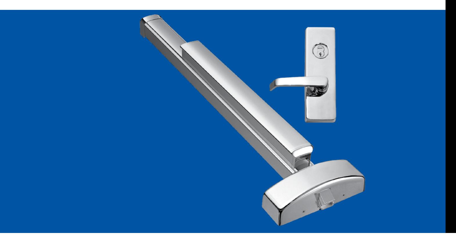
The Apex 2000 Series Touchbar Style Exit Device is highly regarded by architects and end-users alike. Many of the nation's largest healthcare and educational facilities prefer the Apex for it's aesthetic design and efficient engineering. All Apex 2000 Series Exit Devices are UL listed for panic and fire hardware and are certified to ANSI A156.3 Grade 1. Several models are also certified for hurricane resistant applications.
A complete offering of mechanical and electrical options provide a wide range of exit device security solutions. However, the traditional core strenghts of the product can't be overstated. Simple operation with few moving parts, manufactured with true ANSI/BHMA architectural finishes. The chassis is constructed from investment cast steel and the universal mounting holes provide an easier retrofit installation.
Quiet Operation
Sound Dampeners reduce the noise associated with Exit Device operation on the depression and return stroke of the Touchpad.
Touchbar Clearance
The Apex Wide Stile Series Exit Devices accommodate doors with vision lites or glass windows where the vision lite frames or moldings project up to 1/4 beyond the face of the door. The Active Case and End Cap Mounting Bracket are mounted on the face of the door without shims or without cutting the glass molding. These devices have a 1/4" gap between the face of the door and the Touchbar Assembly. This gap allows proper functioning of the devices even on doors which are not perfectly flat. Since the Active Case is mounted directly on the face of the door, it accommodates standard lengths of through bolting screws, thumbpieces, knob & lever Trim fingers, and cylinder tail pieces.
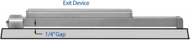
Door (Top View)

General Information
Base Materials
| Finishes | ANSI/BHMA | US | Aluminum | Brass | Bronze | Stainless Steel |
|---|---|---|---|---|---|---|
| Polished Brass, Clear Coated | 605 | US3 | –– | A,B,C,D,E,F,G,H | –– | –– |
| Satin Brass, Clear Coated | 606 | US4 | –– | A,B,C,D,E,F,G,H | –– | –– |
| Satin Bronze, Clear Coated | 612 | US10 | –– | –– | A,B,C,D,E,F,G,H | –– |
| Dark Oxidized Satin Bronze | 613 | US10B | –– | –– | A,B,C,D,E,F,G,H | –– |
| Black, Powder Coated | 622 | US19 | –– | –– | –– | A,B,C,D,E,F,G,H |
| Satin Chrome, Weatherized | 626W | US26D | –– | A,B,C,D,E,F,G,H | –– | –– |
| Satin Aluminum, Clear Anodized | 628 | US28 | A,E,F | –– | –– | B,C,D,G,H |
| Satin Stainless Steel | 630 | US32D | –– | –– | –– | A,B,C,D,E,F,G,H |
| Dark Bronze, Powder Coated | 690 | US20 | –– | –– | –– | A,B,C,D,E,F,G,H |
Finishes
| ANSI/BHMA | US | Description |
|---|---|---|
| 605 | US3 | Polished Brass, Clear Coated |
| 606 | US4 | Satin Brass, Clear Coated |
| 612 | US10 | Satin Bronze, Clear Coated |
| 613 | US10B | Dark Oxidized Satin Bronze |
| 622 | US19 | Black, Powder Coated |
| 625 | US26 | Polished Chromium Plated |
| 626W | US26D | Satin Chrome, Weatherized |
| 628 | US28 | Satin Aluminum, Clear Anodized |
| 630 | US32D | Satin Stainless Steel |
| 630AM | US32D | Satin Stainless Steel, Antimicrobial |
| 690 | US20 | Dark Bronze, Powder Coated |
| Mullion finishes | ||
| 600 | USP | Primed for Paint |
| 689 | Aluminum Paint | |
| 695 | Dark Bronze Paint |
Fasteners
Furnished standard with machine screws and full thread wood/ sheet metal screws. Specify Sex Nuts and Bolts (SNB) where recommended or required by the door manufacturer.
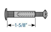
Sex Nuts & Bolts (not furnished std.)
Sex Nuts & Bolts are furnished with No. 10-24 x 1" OHMS (1-1/2" long screws required for guides).
Security Screws
All exposed screws will be a Torx pin in tamper resistant type, machine screws only. Specify (SEC) Security Screws. Cover Screws use a T20 driver, End Cap Screws use a T25 driver.
Door Sizes
Stock sizes for door widths and heights are listed below. If required, cut to size in the field.
| Door Widths | Stock Sizes |
|---|---|
| 2'-0" to 2'-6" | 2'-6"* |
| 2'-7" to 3'-0" | 3'-0" |
| 3'-1" to 4'-0" | 4'-0" |
* Not available for Narrow Stile Devices.
Vertical Rod Devices
| Device | Door Heights | Stock Sizes |
|---|---|---|
|
Surface Vertical
Rod Device* |
up to 7'-0"
7'-1" to 8'-0" 8'-1" to 10'-0" |
7'-0"
8'-0" 10'-0" |
|
Concealed Vertical
Rod Device |
6'-8" to 8'-0"
8'-1" to 10'-0" |
8'-0"
10'-0" |
* Surface Vertical Rods are furnished of the same material as the device. Stainless steel rods are furnished for 625, 628 and 630 devices.
Hand of Doors
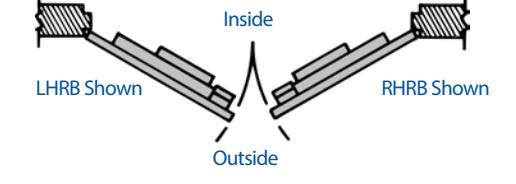


Rim Exit Devices
Apex 2100 Series - Reversible Apex FL2100 Fire Exit Series - Reversible
Doors – For all types of single and double doors with a mullion. For mullions, see page 18. Available for 1-3/4" to 2-1/4" thick, up to 4'-0" wide opening. For thicker doors, consult factory. Furnished standard for 1-3/4" thick, 3'-0" wide opening.
Device – Covers ANSI A115.2 (Type 161), A115.18 cylinder lock and A115.1 (Type 86) Mortise Lock preparation.
Functions – Functions are field selectable except for the Double Cylinder option. The device is furnished for a desired function if specified. If not specified the "03" function is furnished standard.
Double Cylinder – Handed, "10" Function available. Requires two rim type cylinders, not furnished standard. See page 5 and 19.
Base Material – The Cover, Touchbar, Device Channel, Lock/Hinge Side Filler and End Cap are furnished of heavy wrought Brass, Bronze or Stainless Steel. 628 Devices are furnished with Aluminum, Brass, Bronze and Stainless Steel components. See "Finish & Base Material" chart page 3.
Chassis – Investment Cast Steel, Zinc Dichromated.
Latchbolt – Stainless Steel, Deadlocking, 3/4" throw.
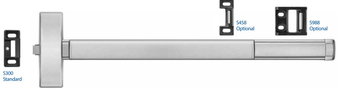
Strikes – No. S300, Investment Cast Stainless Steel, Black Powder Coated furnished standard. No. S988, optional strike for use on Aluminum Door applications, please specify when ordering. No. S458, optional strike for use on Mullion applications, please specify when ordering. For optional strike information see page 34.
Dogging – 1/4" turn hex key dogging standard. NOT available on Fire Exit Hardware.
Touchbar Height – 39-15/16" from floor standard. May be varied as situation dictates.
Reversible – Reversible for all functions and Trims. Standard packaging RHRB.
UL Listed – Panic and Fire Exit Hardware. For FIRE EXIT HARDWARE Ratings see page 33. Conforms to UL10C and UBC 7-2.
ANSI/BHMA – Devices are BHMA certified for ANSI 156.3, Grade 1.
Finishes –
• 605 • 612 • 622 • 626W • 630 • 606 • 613 • 625 • 628 • 690
For Finish description see page 3.
Cylinders – Rim Type, not furnished standard. Specify when required. For cylinder details see page 19.
Stile Width – See Stile Information on page 36.
Retrofit Applications – The 2100 and FL2100 Series Devices
are designed to retrofit into other manufacturers' mounting hole locations. 1700 Series Pull Trim and 4900 Series Lever Trim may also be factory set for these applications by specifying prefix "R" (e.g. 2108 R4908A). Consult factory for details.
Apex 21 Series – Nonhanded
The 21 Series Device is designed to be compatible with many manufacturers' Access Control exterior trim. The device incorporates a center driven cam to receive the tailpiece of the access control product. The tailpiece rotation required to retract the latch is a minimum of 50 degrees. Consult factory for details.
DEVICE OPTIONS
| Prefix | Description | Page |
|---|---|---|
| C | Quick Connect Plugs39 | |
| DE | Delayed Egress24 | |
| E | Electric Device28 | |
| ELR | Electric Latch Retraction21 | |
| FL | Fire Exit Hardware4 | |
| HC | Windstorm and Hurricane Code Device20 | |
| LDS | Latchbolt Monitoring Double Switch29 | |
| LS | Latchbolt Monitoring Switch29 | |
| MLR | Motorized Latch Retraction40-41 | |
| Q | Wireless Access Management System30-32 | |
| TDS | Touchbar Monitoring Double Switch29 | |
| TS | Touchbar Monitoring Switch29 | |
| WTDS | Weatherized Touchbar Mon. Dbl. Switch29 | |
| WTS | Weatherized Touchbar Monitoring Switch29 | |
| To specify add Prefix to Device No. (e.g. TS2103) |
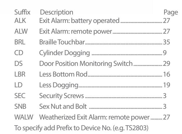
| Suffix | Description | Page |
|---|---|---|
| ALK | Exit Alarm: battery operated27 | |
| ALW | Exit Alarm: remote power27 | |
| BRL | Braille Touchbar35 | |
| CD | Cylinder Dogging19 | |
| DS | Door Position Monitoring Switch29 | |
| LD | Less Dogging19 | |
| SEC | Security Screws3 | |
| SNB | Sex Nut and Bolt3 | |
| WALW | Weatherized Exit Alarm: remote power27 | |
| To specify add Suffix to Device No. (e.g. 2103CD) |

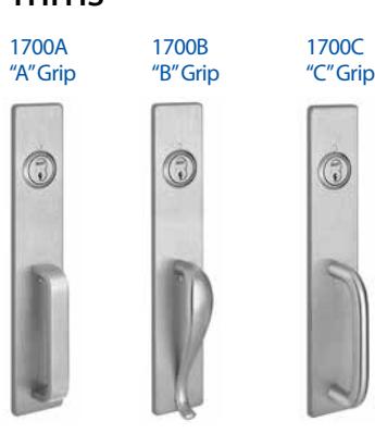
Trims

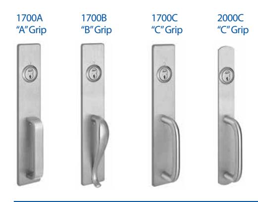
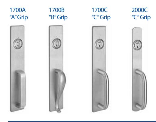
- 1. All Trims are furnished with wrought plates and extruded or cast solid grips.
- 2. Specify Grip Design (A,B,C) ("A" Grip furnished standard for 1700 Series Trim, "C" Grip furnished standard for 2000 Series Trim)
- 3. 630 Trim is furnished for 628 Devices.
- 4. 626 Trim is furnished for 626W Devices.
Retrofit Applications
The R1700 Series Trim is designed to retrofit into other manufacturers' installations when used with the wide stile Apex Series Devices. Consult factory for details.
V4908A
Vandal Resistant Trim
A heavy duty lever trim designed to withstand abuse and vandalism. Composed of extra strength shock-absorbing "overload" springs and heavy duty investment cast stainless steel internal components. Lever returns to the "home" position eliminating the need to reset the lever.
Retrofit Applications
The R4900 Series Trim is designed to retrofit into other manufacturers' installations when used with the wide stile Apex Series Devices. Consult factory for details.
- For Trim dimensions see page 38.
- Trims are BHMA certified for ANSI 156.3, Grade 1.
- Trims are through bolted and will cover 161 and 86 cutouts (except for 2000C Trim).
- Cylinder, Rim Type, not furnished standard. For cylinder details see page 19.
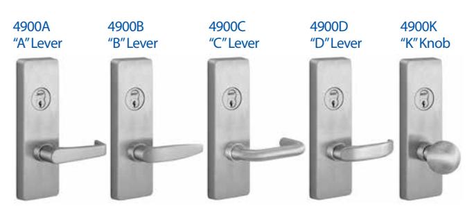
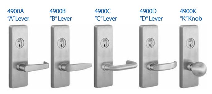
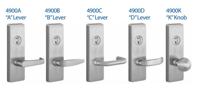
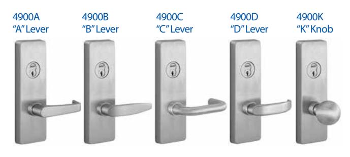
| 1. All the escutcheons and levers are castings or forgings. | ||
|---|---|---|
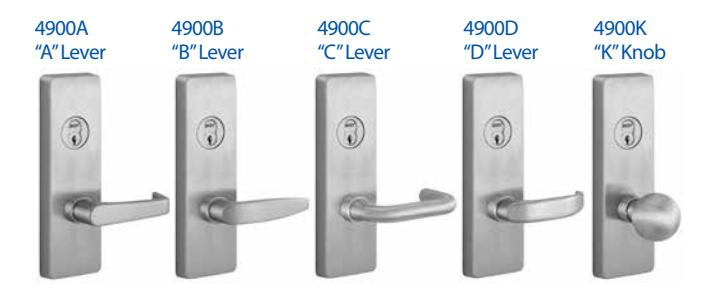
- 2. Specify Lever or Knob Design (A,B,C,D,K) and Handing ("A" Lever x RHRB furnished standard)
- 3. 626 Trim furnished for 626W, 628 and 630 Devices.
|
ANSI Func
tion |
01
Exit Only (cover plate) |
02
Dummy Trim |
03
Key Retracts Latchbolt |
05
Key Locks/ Unlocks Thumbpiece |
08
Key Locks/Unlocks Lever/Knob |
10*
Double Cylinder Inside Key Locks/ Unlocks Lever/Knob |
14
No Cylinder Lever/Knob Always Active |
15
No Cylinder Thumbpiece Always Active |
|---|---|---|---|---|---|---|---|---|
| Device Nos. |
2101
FL2101 |
2102 |
2103**
FL2103** |
2105
FL2105 |
2108
FL2108 |
2110
FL2110 |
2114
FL2114 |
2115
FL2115 |
| Trim Nos. |
1701, R1701,
2001, 4901, R4901 |
1702A, R1702A,
2002C, 4902A, R4902A |
1703A, R1703A,
2003C, 4903A, R4903A |
1705A, R1705A,
2005C |
4908A, V4908A,
R4908A, RV4908A |
4908A, V4908A,
R4908A, RV4908A |
4914A,
R4914A |
1715A,
R1715A, 2015C |
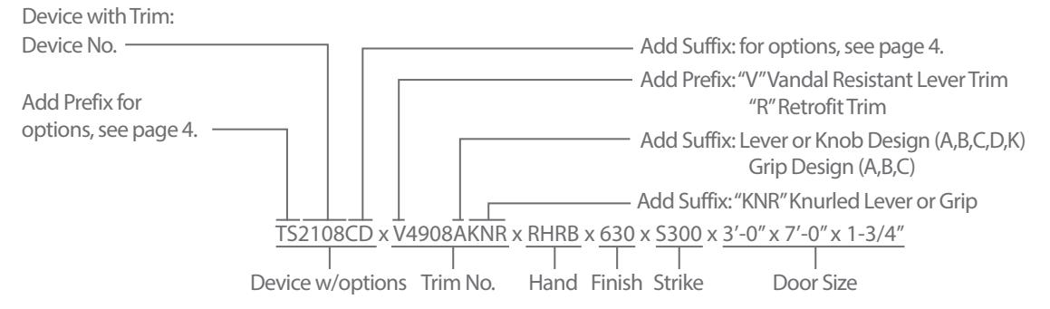
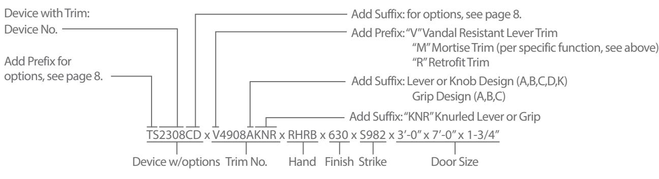
Device Only: Device no., hand, finish, strike, and door size including thickness: (e.g. TS2108CD x RHRB x 630 x S300 x 3'-0" x 7'-0" x 1-3/4") Trim Only: Trim no., hand, finish, strike, and door size including thickness: (e.g. V4908A x RHRB x 626 x 1-3/4")
* & quot;10" Function is handed
** 2103 & amp; FL2103 x Cylinder Only Application includes Cylinder Attachment Kit "CA-03"
Surface Vertical Rod Exit Devices
S300
Apex 2200 Series - Reversible Apex FL2200 Fire Exit Series - Reversible
Doors – For all types of single and double door applications. Available for 1-3/4" to 2-1/4" thick, up to 4'-0" wide by 10'-0" high openings. For thicker doors, consult factory. Furnished standard for 1-3/4" thick, 3'-0" wide by 7'-0" high openings.
Device – Covers ANSI A115.2 (Type 161), A115.18 cylinder lock and A115.1 (Type 86) Mortise Lock preparation.
Functions – Functions are field selectable. The device is furnished for a desired function if specified. If not specified the "03" function is furnished standard.
Base Material – The Covers, Touchbar, Device Channel, Lock/Hinge Side Filler, Vertical Rods and End Cap are furnished of heavy wrought Brass, Bronze or Stainless Steel. US28 Devices are furnished with Aluminum, Brass, Bronze and Stainless Steel components. See "Finish & Base Material" chart on page 3.
Chassis – Investment Cast Steel, Zinc Dichromated.
Top Latchbolt – Stainless Steel, Deadlocking, 3/4" throw. Bottom Bolt – Steel plated, independent action 5/8" throw, with adjustment range to suit 3/4" door undercut.
Top Strike – No. S300 Surface applied, Investment Cast Stainless Steel, Black Powder Coated furnished standard. For optional strikes see page 34.
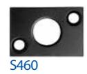
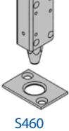
Bottom Strike – No. S460, Flush mounted, Steel, Black Powder Coated.
UL Listed – Panic and Fire Exit Hardware. For FIRE EXIT HARDWARE Ratings see page 33. Conforms to UL10C and UBC 7-2.
ANSI/BHMA – Devices are BHMA certified ANSI 156.3, Grade 1.
Finishes –
• 605 • 612 • 622 • 626W • 630 • 606 • 613 • 625 • 628 • 690
For finish description see page 3.
Cylinders – Rim type, not furnished standard. Specify when required. For cylinder details see page 19.
Stile Width – See Stile Information on page 36.
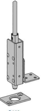
Less Bottom Rod (LBR) Option – Specify suffix "LBR" (e.g. 2208LBR). See UL FIRE LABEL RATING chart on page 39. Fire Rated Devices include FB277 Fire Bolt Assembly. For Fire Bolt Assembly image see page 35.
Retrofit Applications – The 2200 and FL2200 Series Devices are designed to retrofit into other manufacturers' mounting hole locations. 1700 Series Pull Trim and 4900 Series Lever Trim may also be factory set for these applications by specifying prefix "R" (e.g. 2208 R4908A).
Apex 22 Series - Reversible
The 22 Series Device is designed to be compatible with
Dogging – 1/4" turn hex key dogging standard. NOT available on Fire Exit Hardware.
Touchbar Height – 39-15/16" from floor standard. Specify required height if other than standard.
Reversible – Reversible for all functions and trims. Standard packing RHRB.
many manufacturers' Access Control exterior trim. The device incorporates a center driven cam to receive the tailpiece of the access control product. The tailpiece rotation required to retract the latch is a minimum of 50 degrees. Consult factory for details.
Device Options
| Prefix | Description | Page |
|---|---|---|
| C | Quick Connect Plugs39 | |
| E | Electric Device28 | |
| ELR | Electric Latch Retraction21 | |
| DE* | Delayed Egress24 | |
| FL | Fire Exit Hardware6 | |
| HC | Windstorm and Hurricane Code Device20 | |
| LS | Latchbolt Monitoring Switch29 | |
| MLR | Motorized Latch Retraction40-41 | |
| Q | Wireless Access Management System30-32 | |
| TDS | Touchbar Monitoring Double Switch29 | |
| TS | Touchbar Monitoring Switch29 | |
| WTDS | Weatherized Touchbar Mon. Dbl Switch29 | |
| WTS | Weatherized Touchbar Mon. Switch29 |
| Suffix | Description | Page |
|---|---|---|
| ALK | Exit Alarm: battery operated27 | |
| ALW | Exit Alarm: remote power27 | |
| BRL | Braille Touchbar35 | |
| CD | Cylinder Dogging19 | |
| DS | Door Position Monitoring Switch29 | |
| LBR | Less Bottom Rod6 | |
| LD | Less Dogging19 | |
| SEC | Security Screws3 | |
| SNB | Sex Nut and Bolt3 | |
| TMB | Transom Bracket35 | |
| WALW | Weatherized Exit Alarm: remote power27 | |
| To specify add Prefix to Device No. (e.g. TS2203) |
To specify add Prefix to Device No. (e.g. TS2203)
* Rod guards are required. They are supplied by other manufacturers.

Trims
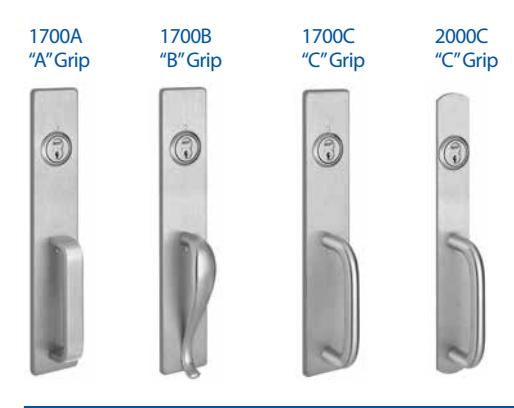
- 1. All Trims are furnished with wrought plates and extruded or cast solid grips.
- 2. Specify Grip Design (A,B,C) ("A" Grip furnished standard for 1700 Series Trim, "C" Grip furnished standard for 2000 Series Trim)
- 3. 630 Trim is furnished for 628 Devices.
- 4. 626 Trim is furnished for 626W Devices.
Retrofit Applications
The R1700 Series Trim is designed to retrofit into other manufacturers' installations when used with the wide stile Apex Series Devices. Consult factory for details.
V4908A
Vandal Resistant Trim
A heavy duty lever trim designed to withstand abuse and vandalism. Composed of extra strength shock-absorbing "overload" springs and heavy duty investment cast stainless steel internal components. Lever returns to the "home" position eliminating the need to reset the lever.
Retrofit Applications
The R4900 Series Trim is designed to retrofit into other manufacturers' installations when used with the wide stile Apex Series Devices. Consult factory for details.
- For Trim dimensions see page 38.
- Trims are BHMA certified for ANSI 156.3, Grade 1.
- Trims are through bolted and will cover 161 and 86 cutouts (except for 2000C Trim).
- Cylinder, Rim Type, not furnished standard. For cylinder details see page 19.
| 1. All the escutcheons and levers are castings or forgings. | |||
|---|---|---|---|
- 2. Specify Lever or Knob Design (A,B,C,D,K) and Handing ("A" Lever x RHRB furnished standard)
- 3. 626 Trim furnished for 626W, 628 and 630 Devices.
|
ANSI
Function |
01
Exit Only (cover plate) |
02
Dummy Trim |
03
Key Retracts Latchbolt |
05
Key Locks/Unlocks Thumbpiece |
08
Key Locks/Unlocks Lever/Knob |
14
No Cylinder Lever/Knob Always Active |
15
No Cylinder Thumbpiece Always Active |
|---|---|---|---|---|---|---|---|
| Device Nos. |
2201
FL2201 |
2202 |
2203*
FL2203* |
2205
FL2205 |
2208
FL2208 |
2214
FL2214 |
2215
FL2215 |
| Trim Nos. |
1701, R1701,
2001, 4901, R4901 |
1702A, R1702A,
2002C, 4902A, R4902A |
1703A, R1703A,
2003C, 4903A, R4903A |
1705A, R1705A,
2005C |
4908A, V4908A,
R4908A, RV4908A |
4914A, R4914A |
1715A,
R1715A, 2015C |
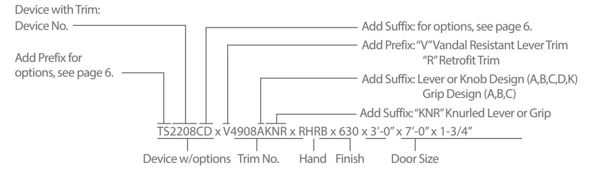
Device Only:Device no., hand, finish, strike, and door size including thickness: (e.g. TS2208CD x RHRB x 630 x 3'-0" x 7'-0" x 1-3/4") Trim Only: Trim no., hand, finish, strike, and door size including thickness: (e.g. V4908A x RHRB x 626 x 1-3/4")
* 2203 & amp; FL2203 x Cylinder Only Application includes Cylinder Attachment Kit "CA-03"
Mortise Exit Devices
Apex 2300 Series - Handed Apex FL2300 Fire Exit Series - Handed
Doors – For all types of single and double door applications. Available for 1-3/4" thick, up to 4-0" wide opening. Furnished standard for 1-3/4" thick, 3'-0" wide opening.
Device – Covers ANSI A115.1 (Type 86) Mortise Lock preparation. Double Cylinder – Handed, "10" Function available. Requires one rim type cylinder and one 1-1/4" long mortise type cylinder, not furnished standard. See page 9 and 19.
Base Material – The Cover, Touchbar, Device Channel, Lock/ Hinge Side Filler and End Cap are furnished of heavy wrought Brass, Bronze or Stainless Steel. US28 Devices are furnished with Aluminum, Brass, Bronze and Stainless Steel components. See "Finish & Base Material" chart on page 3.
Chassis – Investment Cast Steel, Zinc Dichromated.
Dogging – 1/4" turn hex key dogging standard. NOT available on Fire Exit Hardware.
Touchbar Height – 39-15/16" from floor standard.
Handed – Specify hand when ordering as RHRB or LHRB. Touchbar Assembly, Mortise Lock and Trim may be reversed in the field. For reversibility of complete device, mortise strike is required for the other hand.
UL Listed – Panic and Fire Exit Hardware. For FIRE EXIT HARDWARE Ratings see page 33. Conforms to UL10C and UBC 7-2.
ANSI/BHMA – Devices are BHMA certified for ANSI 156.3, Grade 1.
Finishes –
• 605 • 612 • 625 • 628 • 606 • 613 • 626W • 630
For finish description see page 3.
Stile Width – See Stile Information on page 36.
Cylinders – Mortise type, not furnished standard. For cylinder details see page 19.
Retrofit Applications – The 2300 and FL2300 Series Devices are designed to retrofit into other manufacturers' mounting hole locations. 1700 Series Pull Trim and 4900 Series Lever Trim may also be factory set for these applications by specifying prefix "R" (e.g. 2308 R4908A). Consult factory for details.
Exit Series - Handed
Fits doors machined per ANSI A115.1 (Type 86) Mortise Lock preparation.
Backset – 2-3/4".
Case – Wrought Steel, Zinc Dichromate finish.
Lock Front Plate – 8" x 1-1/4" Bronze, Brass or Stainless Steel, pivots for beveled or square edged doors.
Latchbolt – Stainless Steel, Deadlocking, 3/4" throw, anti-friction.
Guardbolt – Stainless Steel, sliding type.
Finishes – LOCK FRONT PLATE and STRIKE 605, 606, 612, 613, 622, 625, 630, 690. 630 furnished for 626 and 628 locks. For finish description see page 3.
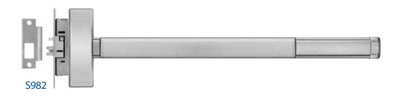
Strikes – No. S982, handed curved lip strike furnished standard. For optional strikes see page 34.
Lock No.
- M303: 01, 02 & 03 functions.
- M308: 05, 08, 14 & 15 functions.
- M310: 10 function.
NOTE - For Mortise Lock dimensions see page 28. For Mortise Lock with Electrical options see page 28.
Device Options Prefix Description Page C Quick Connect Plugs................................................39 DE Delayed Egress............................................................24 E Electric Lock/Unlock.................................................28 ELR Electric Latch Retraction.........................................21 FL Fire Exit Hardware......................................................8 HC Windstorm and Hurricane Code Device........20 LS Auxiliary Latchbolt Monitoring, "03"Function.................................................................28, 29 LS Latchbolt and Trim locked or unlocked monitoring, "08" Function......................................28, 29 MLR Motorized Latch Retraction..................................40-41 TDS Touchbar Monitoring Double Switch..............29 TS Touchbar Monitoring Switch...............................29
To specify add Prefix to Device No. (e.g. TS2203)
| Suffix | Description | Page |
|---|---|---|
| ALK | Exit Alarm: battery operated27 | |
| ALW | Exit Alarm: remote power27 | |
| BRL | Braille Touchbar35 | |
| CD | Cylinder Dogging19 | |
| DS | Door Position Monitoring Switch29 | |
| LD | Less Dogging19 | |
| SEC | Security Screws3 | |
| SNB | Sex Nut and Bolt3 | |
| WALW | Weatherized Exit Alarm: remote power27 | |
| To specify add Suffix to Device No. (e.g. 2303CD) |

Trims
- 1. All Trims are furnished with wrought plates and extruded or cast solid grips.
- 2. Specify Grip Design (A,B,C) ("A" Grip furnished standard for 1700 Series Trim, "C" Grip furnished standard for 2000 Series Trim)
- 3. 630 Trim is furnished for 628 Devices.
- 4. 626 Trim is furnished for 626W Devices.
Note: B & C grip pull handles are not available in the 05 and 15 functions.
Retrofit Applications
The R1700 Series Trim is designed to retrofit into other manufacturers' installations when used with the wide stile Apex Series Devices. Consult factory for details.
V4908A
Vandal Resistant Trim
A heavy duty lever trim designed to withstand abuse and vandalism. Composed of extra strength shock-absorbing "overload" springs and heavy duty investment cast stainless steel internal components. Lever returns to the "home" position eliminating the need to reset the lever.
Retrofit Applications
The R4900 Series Trim is designed to retrofit into other manufacturers' installations when used with the wide stile Apex Series Devices. Consult factory for details.
- For Trim dimensions see page 38.
- Trims are BHMA certified for ANSI 156.3, Grade 1.
- Trims are through bolted and will cover 161 and 86 cutouts (except for 2000C Trim).
- Cylinder, Mortise Type, not furnished standard. For cylinder details see page 19.
- 1. All the escutcheons and levers are castings or forgings.
- 2. Specify Lever or Knob Design (A,B,C,D,K) and Handing ("A" Lever x RHRB furnished standard)
- 3. 626 Trim furnished for 626W, 628 and 630 Devices.
- 4. All Lever Trims, M4908K and M4914K are Handed, Specify Hand.
|
ANSI Func
tion |
01
Exit Only (cover plate) |
02
Dummy Trim |
03
Key Retracts Latchbolt |
05
Key Locks/ Unlocks Thumbpiece |
08
Key Locks/Unlocks Lever/Knob |
10*
Double Cylinder Inside Key Locks/ Unlocks Lever/Knob |
14
No Cylinder Lever/Knob Always Active |
15
No Cylinder Thumbpiece Always Active |
|---|---|---|---|---|---|---|---|---|
| Device Nos. |
2301
FL2301 |
2302 |
2303
FL2303 |
2305
FL2305 |
2308
FL2308 |
2310
FL2310 |
2314
FL2314 |
2315
FL2315 |
| Trim Nos. |
1701, R1701,
2001, 4901, R4901 |
1702A, R1702A,
2002C, 4902A, R4902A |
1703A, R1703A,
2003C, M4903A, MR4903A |
M1705A,
RM1705A, |
M4908A,
VM4908A, RM4908A, VRM4908A |
M4908A,
VM4908A, RM4908A, VRM4908A |
M4914A,
RM4914A |
M1715A,
RM1715A, |
Device Only: Device no., hand, finish, strike, and door size including thickness: (e.g. TS2108CD x RHRB x 630 x S982 x 3'-0" x 7'-0" x 1-3/4") Trim Only: Trim no., hand, finish, strike, and door size including thickness: (e.g. VM4908A x RHRB x 626 x 1-3/4")
Rim Exit Devices
S458 Optional for Hollow Metal Door or Mullion applications
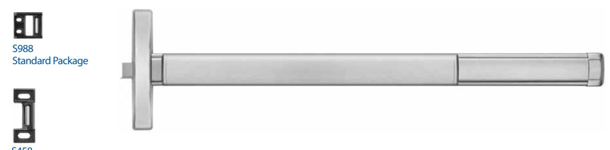
Apex 2400 Series - Non Handed Apex FL2400 Fire Exit Series - Non Handed
Doors – For all types of single and double doors with a mullion. For mullions, see page 18. Available for 1-3/4" to 2-1/4" thick, up to 4'-0" wide opening. For thicker door, consult factory. Furnished standard for 1-3/4" thick, 3'-0" wide opening.
Functions – A Universal Exit Device. Add Trim for desired function.
Base Material – The Cover, Touchbar, Device Channel, Lock/Hinge Side Filler and End Cap are furnished of heavy wrought Brass, Bronze or Stainless Steel. US28 Devices are furnished with Aluminum, Brass, Bronze and Stainless Steel components. See "Finish & Base Material" chart on page 3.
Chassis – Investment Cast Steel, Zinc Dichromated.
Latchbolt – Stainless Steel, Deadlocking, 3/4" throw.
Strikes – No. S988, standard package for Aluminum Door applications, Black Powder Coated Stainless Steel Roller Strike. No. S458, optional for Hollow Metal Door or Mullion applications, please specify when ordering. For optional strike information see page 34.
Dogging – 1/4" turn hex key dogging standard. NOT available on Fire Exit Hardware.
Touchbar Height – 39-15/16" from floor standard. May be varied as situation dictates.
UL Listed – Panic and Fire Exit Hardware. For FIRE EXIT HARDWARE Ratings see page 33. Conforms to UL10C and UBC 7-2.
ANSI/BHMA – Devices are BHMA certified for ANSI 156.3, Grade 1.
Finishes –
• 605 • 612 • 622 • 626W • 630 • 606 • 613 • 625 • 628 • 690
For finish description see page 3.
Cylinders – Rim Type for "03" function, Mortise type for "08" function. Use 1-1/4" long standard mortise cylinder. Cylinders are not furnished standard. Specify when required. For cylinder details see page 19.
Stile Width – See Stile Information on page 37.
DEVICE OPTIONS
| Prefix | Description | Page |
|---|---|---|
| C | Quick Connect Plugs39 | |
| DE | Delayed Egress24 | |
| ELR | Electric Latch Retraction21 | |
| FL | Fire Exit Hardware10 | |
| MLR | Motorized Latch Retraction40-41 | |
| TDS | Touchbar Monitoring Double Switch29 | |
| TS | Touchbar Monitoring Switch29 | |
| WTDS | Weatherized Touchbar Mon. Dbl. Switch29 | |
| WTS | Weatherized Touchbar Monitoring Switch29 | |
| To specify add Prefix to Device No. (e.g. TS2403) | ||
| Suffix | Description | Page |
|---|---|---|
| ALK | Exit Alarm: battery operated27 | |
| ALW | Exit Alarm: remote power27 | |
| BRL | Braille Touchbar35 | |
| CD | Cylinder Dogging19 | |
| DS | Door Position Monitoring Switch29 | |
| LD | Less Dogging19 | |
| SEC | Security Screws3 | |
| SNB | Sex Nut and Bolt3 | |
| WALW | Weatherized Exit Alarm: remote power27 | |
To specify add Suffix to Device No. (e.g. 2403CD)

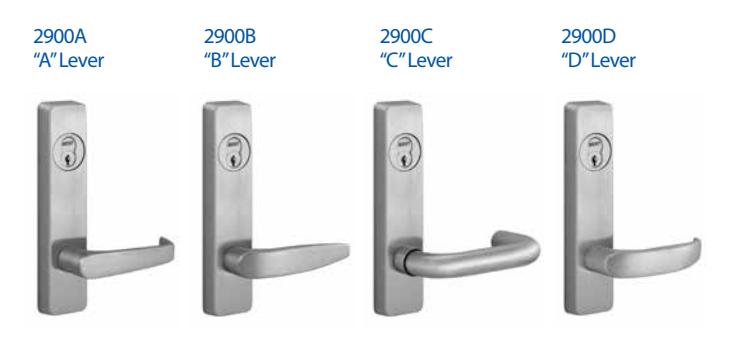
Trims
• Cylinder, not furnished standard – Rim type for "03" function, 1-1/4"long mortise type for "08" function. For cylinder details see page 19.
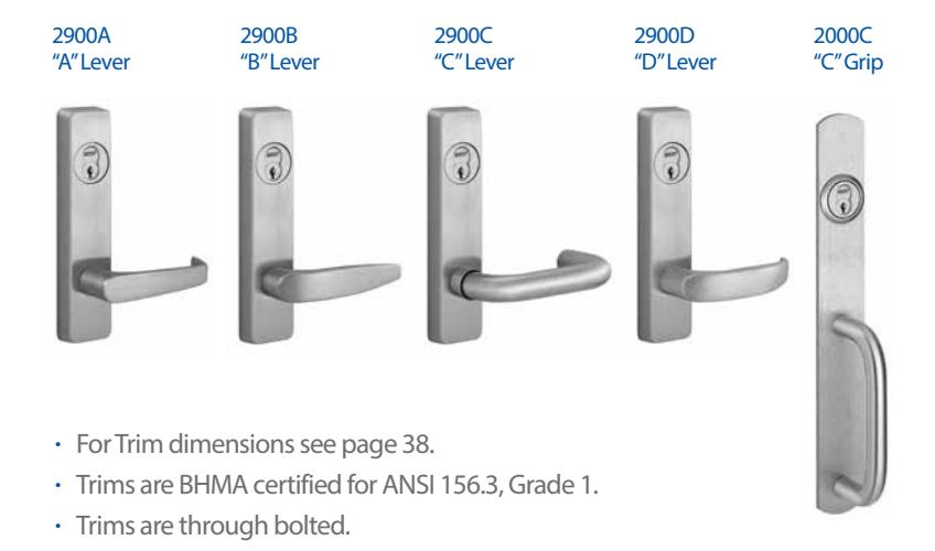
- 1. All the escutcheons and levers are castings or forgings.
- 2. For Lever Trim specify Lever Design (A, B, C, D) and Handing ("A" Lever RHRB furnished standard).
- 3. For 2900 Series Trim, 626 finish is furnished for 628 and 630 Devices.
- 4. 2000 Series Trim is furnished with a wrought plate and extruded solid "C" Grip.
|
ANSI
Function |
01
Exit Only (cover plate) |
02
Dummy Trim |
03
Key Retracts Latchbolt |
08
Key Locks/Unlocks Lever/Knob |
14
No Cylinder Lever/Knob Always Active |
|---|---|---|---|---|---|
| Device Nos. |
2401
FL2401 |
2402 |
2403*
FL2403* |
2408
FL2408 |
2414
FL2414 |
| Trim Nos. | 2901, 2001 | 2902A, 2002C | 2903A, 2003C | 2908A | 2914A |
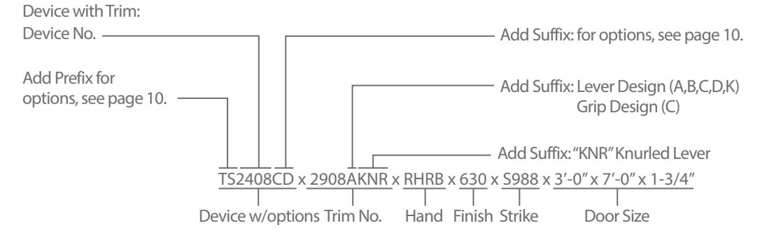
Device Only:Device no., hand, finish, strike, and door size including thickness: (e.g. TS2408CD x RHRB x 630 x S988 x 3'-0" x 7'-0" x 1-3/4") Trim Only: Trim no., hand, finish, strike, and door size including thickness: (e.g. 2908A x RHRB x 626 x 1-3/4")
* 2403 & amp; FL2403 x Cylinder Only Application includes Cylinder Attachment Kit "NCA-03"
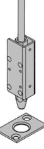
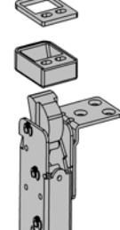
Narrow Concealed Vertical Rod Exit Devices
S519
Apex 2600 Series - Reversible
Apex FL2600 Fire Exit Series - Reversible
Doors – For all types of metal single and double door applications. Available for 1-3/4" thick, up to 4'-0" wide by 10'-0" high openings. For thicker doors, consult factory. Furnished standard for 1-3/4" thick, 3'-0" wide by 6'-8" to 8'-0" high openings.
Functions – A Universal Exit Device. Add Trim for desired function.
Base Material -–Side Filler and End Cap are furnished of heavy wrought Brass, Bronze or Stainless Steel. 628 Devices are furnished with Aluminum, Brass, Bronze and Stainless Steel components. See "Finish & Base Material" chart on page 3.
Chassis – Lock Stile Assembly - Investment Cast Steel, Zinc Dichromated.
Top Latchbolt – Stainless Steel, Deadlocking, 3/4" throw. Bottom Bolt – Steel plated, independent action 5/8" throw, with adjustment range to suit 3/4" door undercut.
Center Chassis – Steel plated, heavy wrought Steel Assembly with lock in place Top and Bottom Latch Adjustors. Adjustment is accessible through the door after installation.
Top Strike – No. S519 Surface applied, Investment Cast Stainless Steel, Black Powder Coated.
Bottom Strike – No. S460, Flush mounted, Steel, Black Powder Coated.
Dogging – 1/4" turn hex key dogging standard. NOT available on Fire Exit Hardware.
Touchbar Height – 39-15/16" from floor standard. Specify required height if other than standard.
UL Listed – Panic and Fire Exit Hardware. For FIRE EXIT HARDWARE Ratings see page 33. Conforms to UL10C and UBC 7-2.
ANSI/BHMA – Devices are BHMA certified for ANSI 156.3, Grade 1.
Finishes –
- 605 613 625 626W 630
- 612 622 626 628 690
For finish description see page 3.
Cylinders – Rim Type for "03" function, 1-1/4" Long Mortise Type for "08" function. Cylinders are not furnished standard. Specify when required. For cylinder details see page 19.
Stile Width – See Stile Information on page 37.
Less Bottom Rod (LBR) Option – Specify suffix "LBR" (e.g. 2603LBR). See UL FIRE LABEL RATING Chart on page 33. Fire Rated Devices include FB277 Fire Bolt Assembly. For Fire Bolt Assembly image see page 35.

| Prefix | Description | Page |
|---|---|---|
| C | Quick Connect Plugs39 | |
| DE | Delayed Egress24 | |
| ELR | Electric Latch Retraction21 | |
| FL | Fire Exit Hardware12 | |
| TDS | Touchbar Monitoring Double Switch29 | |
| TS | Touchbar Monitoring Switch29 | |
| WTDS | Weatherized Touchbar Mon. Dbl. Switch29 | |
| WTS | Weatherized Touchbar Mon. Switch29 | |
| To specify add Prefix to Device No. (e.g. TS2603) |
| Suffix | Description | Page |
|---|---|---|
| ALK | Exit Alarm: battery operated27 | |
| ALW | Exit Alarm: remote power27 | |
| BRL | Braille Touchbar35 | |
| CD | Cylinder Dogging19 | |
| DS | Door Position Monitoring Switch29 | |
| LBR | Less Bottom Rod12 | |
| LD | Less Dogging19 | |
| MLR | Motorized Latch Retraction40-41 | |
| SEC | Security Screws3 | |
| SNB | Sex Nut and Bolt3 | |
To specify add Prefix to Device No. (e.g. TS2603)
WALW Weatherized Exit Alarm: remote power.........27

Trims
- 1. All the escutcheons and levers are castings or forgings.
- 2. For Lever Trim specify Lever Design (A, B, C, D) and Handing ("A" Lever RHRB furnished standard).
- 3. For 2900 Series Trim, 626 finish is furnished for 628 and 630 Devices.
- For Trim dimensions see page 38.
- Trims are BHMA certified for ANSI 156.3, Grade 1.
- Trims are through bolted.
- Cylinder, not furnished standard Rim type for "03" function, 1-1/4"long mortise type for "08" function. For cylinder details see page 19.
|
ANSI
Function |
01
Exit Only (cover plate) |
02
Dummy Trim |
03
Key Retracts Latchbolt |
08
Key Locks/Unlocks Lever/Knob |
14
No Cylinder Lever/Knob Always Active |
|---|---|---|---|---|---|
| Device Nos. |
2601
FL2601 |
2602 |
2603*
FL2603* |
2608
FL2608 |
2614
FL2614 |
| Trim Nos. | 2901, 2001 | 2902A | 2903A | 2908A | 2914A |
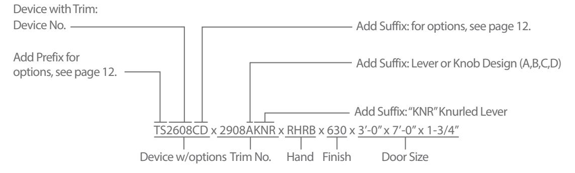
Device Only: Device no., hand, finish, strike, and door size including thickness: (e.g. TS2608CD x RHRB x 630 x 3'-0" x 7'-0" x 1-3/4") Trim Only: Trim no., hand, finish, strike, and door size including thickness: (e.g. 2908A x RHRB x 626 x 1-3/4")
* 2603 & amp; FL2603 x Cylinder Only Application includes Cylinder Attachment Kit "NCA-03"
Wood Door Concealed Vertical Rod Exit Devices
S519
Apex 2700 Series - Reversible
Apex FL2700 Fire Exit Series - Reversible
Doors – For all types of single and double door applications. Available for 1-3/4" to 2-1/4" thick, up to 4'-0" wide by 10'-0" high openings. For thicker doors, consult factory. Furnished standard for 1-3/4" thick, 3'-0" wide by 6'-8" to 8'-0" high openings.
Functions – A Universal Exit Device. Add Trim for desired function.
Base Material – Side Filler and End Cap are furnished of heavy wrought Brass, Bronze or Stainless Steel. 628 Devices are furnished with Aluminum, Brass, Bronze and Stainless Steel components. See "Finish & Base Material" chart on page 3.
Chassis – Lock Stile Assembly - Investment Cast Steel, Zinc Dichromated.
Vertical Rods – Steel, plated. Top Rod is adjustable from 6'-8" to 8'-0" or from 8'-1" to 10'-0". Additional adjustments are available through the lock front filler.
Top Latchbolt – Stainless Steel, Deadlocking, 3/4" throw.
Bottom Bolt – Steel plated, independent action 5/8" throw, with adjustment range to suit 3/4 door undercut.
Top Strike – No. S519 Surface applied, Investment Cast Stainless Steel, Black Powder Coated.
Bottom Strike – No. S460 Flush mounted, Steel, Black Powder Coated.
Dogging – 1/4 turn hex key dogging standard. NOT available on Fire Exit Hardware.
Touchbar Height – 39-15/16 from floor standard. Specify required height if other than standard.
Reversible – Reversible for all functions and trims.Standard packaging RHRB.
UL Listed – Panic and Fire Exit Hardware. For FIRE EXIT HARDWARE Ratings see page 33. Conforms to UL10C and UBC 7-2.
ANSI/BHMA – Devices are BHMA certified for ANSI 156.3, Grade 1.
Finishes –
• 605 • 613 • 625 • 626W • 630 • 612 • 622 • 626 • 628 • 690
For finish description see page 3.
Cylinders – Rim Type, not furnished standard. Specify when required. For cylinder details see page 19.
Stile Width – See Stile Information on page 36.
Less Bottom Rod (LBR) Option – Specify suffix "LBR" (e.g. 2703LBR). See UL FIRE LABEL RATING Chart on page 33. Fire Rated Devices include FB277 Fire Bolt Assembly. For Fire Bolt Assembly image see page 35.

| Prefix | Description | Page |
|---|---|---|
| C | Quick Connect Plugs39 | |
| DE | Delayed Egress24 | |
| E | Electric Device28 | |
| ELR | Electric Latch Retraction21 | |
| FL | Fire Exit Hardware16 | |
| Q | Wireless Access Management System30-32 | |
| LS | Latchbolt Monitoring Switch29 | |
| MLR | Motorized Latch Retraction40-41 | |
| TDS | Touchbar Monitoring Double Switch29 | |
| TS | Touchbar Monitoring Switch29 | |
| WTDS | Weatherized Touchbar Mon. Dbl. Switch29 | |
| WTS | Weatherized Touchbar Mon. Switch29 | |
| To specify add Prefix to Device No. (e.g. TS2803) |
| Suffix | Description | Page |
| ALK | Exit Alarm: battery operated27 | |
| ALW | Exit Alarm: remote power27 | |
| BRL | Braille Touchbar35 | |
| CD | Cylinder Dogging9 | |
| DS | Door Position Monitoring Switch29 | |
| LBR | Less Bottom Rod16 | |
| LD | Less Dogging19 | |
| SEC | Security Screws3 | |
| SNB | Sex Nut and Bolt3 | |
| WALW | Weatherized Exit Alarm: remote power27 | |
To specify add Prefix to Device No. (e.g. TS2803)

Trims
- 1. All Trims are furnished with wrought plates and extruded or cast solid grips.
- 2. Specify Grip Design (A,B,C) ("A" Grip furnished standard for 1700 Series Trim, "C" Grip furnished standard for 2000 Series Trim)
- 3. 630 Trim is furnished for 628 Devices.
- 4. 626 Trim is furnished for 626W Devices.
Retrofit Applications
The R1700 Series Trim is designed to retrofit into other manufacturers' installations when used with the wide stile Apex Series Devices. Consult factory for details.
V4908A
Vandal Resistant Trim
A heavy duty lever trim designed to withstand abuse and vandalism. Composed of extra strength shock-absorbing "overload" springs and heavy duty investment cast stainless steel internal components. Lever returns to the "home" position eliminating the need to reset the lever.
Retrofit Applications
The R4900 Series Trim is designed to retrofit into other manufacturers' installations when used with the wide stile Apex Series Devices. Consult factory for details.
- For Trim dimensions see page 38.
- Trims are BHMA certified for ANSI 156.3, Grade 1.
- Trims are through bolted and will cover 161 and 86 cutouts (except for 2000C Trim).
- Cylinder, Rim Type, not furnished standard. For cylinder details see page 19.
| 1. All the escutcheons and levers are castings or forgings. |
|---|
- 2. Specify Lever or Knob Design (A,B,C,D,K) and Handing ("A" Lever x RHRB furnished standard)
- 3. 626 Trim furnished for 626W, 628 and 630 Devices.
|
ANSI
Function |
01
Exit Only (cover plate) |
02
Dummy Trim |
03
Key Retracts Latchbolt |
05
Key Locks/Unlocks Thumbpiece |
08
Key Locks/Unlocks Lever/Knob |
14
No Cylinder Lever/Knob Always Active |
15
No Cylinder Thumbpiece Always Active |
|---|---|---|---|---|---|---|---|
| Device Nos. |
2701
FL2701 |
2702 |
2703*
FL2703* |
2705
FL2705 |
2708
FL2708 |
2714
FL2714 |
2715
FL2715 |
| Trim Nos. | 1701, 2001, 4901 |
1702A, 2002C,
4902A |
1703A, 2003C,
4903A |
1705A, 2005C | 4908A, V4908A | 4914A | 1715A, 2015A |
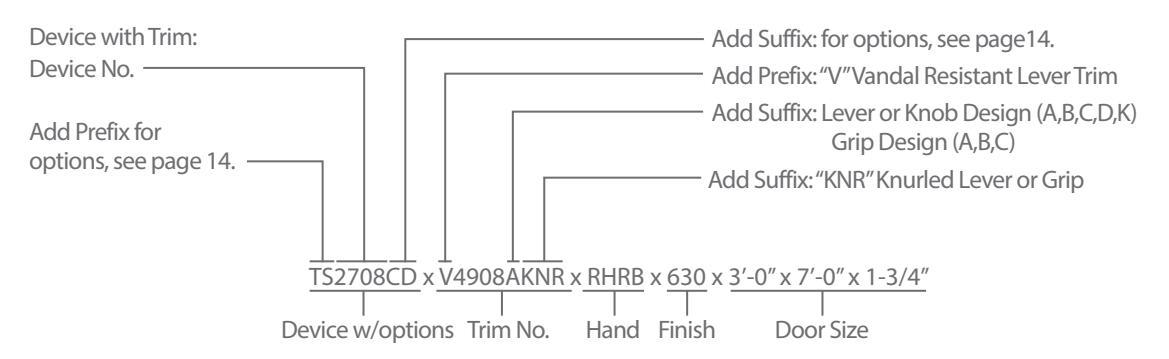
Device Only: Device no., hand, finish, strike, and door size including thickness: (e.g. TS2708CD x RHRB x 630 x 3'-0" x 7'-0" x 1-3/4") Trim Only: Trim no., hand, finish, strike, and door size including thickness: (e.g. V4908A x RHRB x 626 x 1-3/4") * 2703 & FL2703 x Cylinder Only Application includes Cylinder Attachment Kit "CA-03"
Concealed Vertical Rod Exit Devices
Apex 2800 Series - Reversible
Apex FL2800 Fire Exit Series - Reversible
S519
Doors – For all types of metal single and double door applications. Available for 1-3/4" thick, up to 4'-0" wide by 10-0 high openings. For thicker doors, consult factory. Furnished standard for 1-3/4" thick, 3'-0" wide by 6'-8" to 8'-0" high openings.
Functions – Functions are field selectable. The device is furnished for a desired function if specified. If not specified the "03" function is furnished standard.
Base Material – The Cover, Touchbar, Device Channel, Lock/Hinge Side Filler and End Cap are furnished of heavy wrought Brass, Bronze or Stainless Steel. US28 Devices are furnished with Aluminum, Brass, Bronze and Stainless Steel components. See "Base Material and Finish Chart" on page 3.
Chassis – Lock Stile Assembly - Investment Cast Steel, Zinc Dichromated.
Vertical Rods – Steel, plated. Top Rod is adjustable from 6'-8" to 8'-0" or from 8'-1" to 10'-0".
Top Latchbolt – Stainless Steel, Deadlocking, 3/4" throw.
Top Strike – No. S519 Surface applied, Investment Cast Stainless Steel, Black Powder Coated.
Bottom Bolt – Steel plated, independent action 5/8" throw, with adjustment range to suit 3/4" door undercut.
Center Chassis – Steel plated, heavy wrought Steel Assembly with lock in place Top and Bottom Latch Adjustors. Adjustment accessible through the door after installation.
Bottom Strike – No. S460 Flush mounted, Steel, Black Powder Coated.
Dogging – 1/4" turn hex key dogging standard. NOT available on Fire Exit Hardware.
Touchbar Height – 39-15/16" from floor standard. Specify required height if other than standard.
Reversible – Reversible for all functions and trims. Standard packaging RHRB.
UL Listed – Panic and Fire Exit Hardware. For FIRE EXIT HARDWARE Ratings see page 33. Conforms to UL10C and UBC 7-2.
ANSI/BHMA – Devices are BHMA certified for ANSI 156.3, Grade 1.
Finishes –
- 605 612 622 626W 630 • 606 • 613 • 625 • 628 • 690
- For Finish description see page 3.
Cylinders – Rim Type, not furnished standard. Specify when required. For cylinder details see page 19.
Stile Width – See Stile Information on page 36.
Less Bottom Rod (LBR) Option – Specify suffix "LBR" (e.g. 2808LBR). See UL FIRE LABEL RATING chart on page 33. Fire Rated Devices include FB277 Fire Bolt Assembly. For Fire Bolt Assembly image see page 35.
DEVICE OPTIONS
| Prefix | Description | Page |
|---|---|---|
| C | Quick Connect Plugs39 | |
| DE | Delayed Egress24 | |
| E | Electric Device28 | |
| ELR | Electric Latch Retraction21 | |
| FL | Fire Exit Hardware16 | |
| HC | Windstorm and Hurricane Code Device20 | |
| LS | Latchbolt Monitoring Switch29 | |
| MLR | Motorized Latch Retraction40-41 | |
| TDS | Touchbar Monitoring Double Switch29 | |
| TS | Touchbar Monitoring Switch29 | |
| WTDS | Weatherized Touchbar Mon. Dbl. Switch29 | |
| WTS | Weatherized Touchbar Mon. Switch29 | |
To specify add Prefix to Device No. (e.g. TS2803)

Trims
C03 Cast Plate "Pull by others"
The CVR2803 with "Pull by Other" must be specified with No. C03 Cylinder Attachment Trim to secure the Rim Cylinder. Specify finish.
- 1. All Trims are furnished with wrought plates and extruded or cast solid grips.
- 2. Specify Grip Design (A,B,C) ("A" Grip furnished standard for C1700 Series Trim)
- 3. 630 Trim is furnished for 628 Devices.
- 4. 626 Trim is furnished for 626W Devices.
- 1. All the escutcheons and levers are castings or forgings.
- 2. Specify Lever or Knob Design (A,B,C,D,K) and Handing ("A" Lever x RHRB furnished standard)
- 3. 626 Trim furnished for 626W, 628 and 630 Devices.
V4908A
Vandal Resistant Trim
A heavy duty lever trim designed to withstand abuse and vandalism. Composed of extra strength shock-absorbing "overload" springs and heavy duty investment cast stainless steel internal components. Lever returns to the "home" position eliminating the need to reset the lever.
Retrofit Applications
The R4900 Series Trim is designed to retrofit into other manufacturers' installations when used with the wide stile Apex Series Devices. Consult factory for details.
- For Trim dimensions see page 38.
- Trims are BHMA certified for ANSI 156.3, Grade 1.
- Trims are through bolted and will cover 161 and 86 cutouts (except for 2000C Trim).
- Cylinder, Rim Type, not furnished standard. For cylinder details see page 19.
|
ANSI
Function |
01
Exit Only (cover plate) |
02
Dummy Trim |
03
Key Retracts Latchbolt |
05
Key Locks/Unlocks Thumbpiece |
08
Key Locks/Unlocks Lever/Knob |
14
No Cylinder Lever/Knob Always Active |
15
No Cylinder Thumbpiece Always Active |
|---|---|---|---|---|---|---|---|
| Device Nos. |
2801
FL2701 |
2802 |
2803*
FL2803* |
2805
FL2805 |
2808
FL2808 |
2814
FL2814 |
2815
FL2815 |
| Trim Nos. | C1701, 4901 | C1702A, 4902A | C03, C1703A, 4903A | 1705A | 4908A, V4908A | 4914A | C1715A |
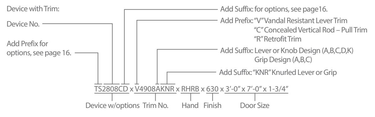
Device Only: Device no., hand, finish, strike, and door size including thickness: (e.g. TS2808CD x RHRB x 630 x 3'-0" x 7'-0" x 1-3/4") Trim Only: Trim no., hand, finish, strike, and door size including thickness: (e.g. V4908A x RHRB x 626 x 1-3/4") * 2803 & FL2803 x Cylinder Only Application requires CO3 trim.
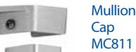
Mullions
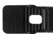
Mullion Cap MC822
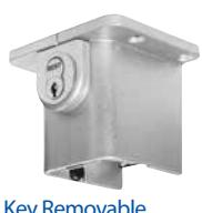
Key Removable Mullion Cap KMC822 (Rim Cylinder required)
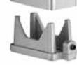
Interlock S1447
Stabilizer ST989
Removable Mullions
The Mullion is used to adapt a double door opening to two single door openings with Rim Exit Devices. When the full width of an opening is required, the mullion may be removed.
Key Removable Mullion (KR) – Provides a secure yet quick & easy means of removing the 822 or FL822 Mullion. The mullion can be reinstalled and locked without the need of the key.
Stock Size – For openings 8'-0" high. For openings less than 8'-0" high the mullion can be cut down. For openings greater than 8'-0" high using the 822, KR822 or 811 mullions, consult factory.
Finishes –
• 600 • 689 • 695
For finish description see page 3.

U.L. Listed – FL822 and FLKR822 listed for Fire Exit Hardware. For FIRE LABEL RATING Chart see page 33.
Mullion – 2" x 3" Steel.
Mullion Base – Investment Cast Steel, 2" wide 3-1/2" deep. Furnished with steel anchors for concrete floors.
Interlock – Black Powder Coated Investment Cast Stainless Steel. Furnished standard for FL822 and FLKR822 Mullions. It interlocks the mullion to the Rim Active Case and S300 or S301 strike.
Stabilizers – Black Powder Coated Steel. Stabilizers are furnished standard for FL822 and FLKR822 Mullions.
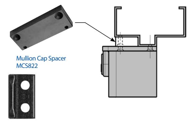
Mullion Cap Spacer – Minimum width 3-1/2". For 2-1/4" frame spacer specify part No. MCS822. For use with 822 series mullion only (e.g. 822, FL822, HC822, HCKR822, KR822, FLKR822). MCS822 Kit or 822 mullion sufix option. See "To Order" example below.
822, FL822 Mullion Cap – MC822 Investment Cast Steel, 4" wide 3-5/8" deep.
KR822, FLKR822 Key Removable Mullion Cap Assembly – Investment Cast Steel - can be ordered to convert existing 822 or FL822 mullions to Keyed Removable Mullions. Retrofits to the hole pattern of an MC822 Mullion Cap. To order, specify: KMC822 or KMC822F.
KR822, FLKR822, HCKR822 Mullion Storage Kit - Set of top and bottom mounting brackets enabling secure storage. Kit includes: 1 ea. KMC822 Top Fitting (Less Rim Cylinder), 1 ea. MB822 Bottom Fitting and 1 ea. AB822SK Top Fitting Angle Bracket. To order, specify: KMCB822SK-Finish. Available in 600, 689 and 695 finishes.
Cylinder – not furnished standard - Rim Type required. See page 19 for cylinder details.
HC822, HCKR822 Mullion
Mullion – 2" x 3" Steel Mullion is reinforced with a 1-1/2" x 2-1/2" 11 gage Steel Tube. MC822 or KMC822 Mullion Cap and MB822 Mullion Base Assemblies are used to secure the HC Mullion in the door opening. The S1447 Interlock must be used to Interlock the Active Case with the strike and is furnished standard with the HC822 Mullion. To Order: Specify Mullion No. Height Finish (e.g. MCS822 x 8'-0" x 600)
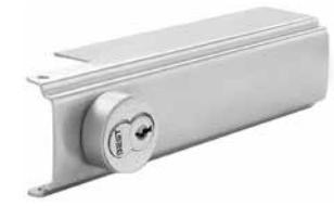
811 Mullion
Mullion – 2" x 2" Steel Mullion.
Mullion Cap – Cast 4-1/2" wide x 2-5/16", furnished with machine screws for metal frames.
Mullion Base – Cast 2" wide x 2-3/4", furnished with sheet metal screws and plastic anchors.
To Order: Specify Mullion No. Height Finish (e.g. 822 x 8'-0" x 600)
Mullion Base MB822
Mullion Base MB811

Cylinder Functions
Cylinder Dogging
Available for all Apex Series Devices except Fire Exit Hardware and Delayed Egress Devices.
Cylinder Dogging provides the ability to lock down the touch bar with a key cylinder so the door can be used in the push/pull mode. To order, specify suffix "CD" (e.g. 2103CD). Requires the use of a 1-1/4 mortise cylinder, not furnished standard. Specify when required.
Less Dogging
Available for all Apex Series Devices except Fire Exit
Cylinder Dogging Kit
To convert from hex key dogging to cylinder dogging in the field, a cylinder dogging kit is available. The kit consists of a channel filler, blocking ring, cylinder locator and lock nut. Requires the use
of a 1-1/4" mortise cylinder, not furnished standard. Specify when required.
To Order: specify CDK-3, NCDK-3 for up to 3-0 and CDK4, NCDK-4 for devices up to 4-0.
Note: The channel fillers are different lengths for narrow and wide stile devices. "NCDK" - Narrow Cylinder Dogging Kit.
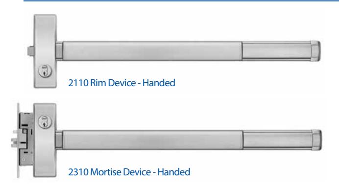
Double Cylinder - Handed ("10" Function)
The Double Cylinder option is available on the Wide Stile Rim and Mortise Exit Devices. The inside key cylinder locks or unlocks the outside Trim and the outside key cylinder retracts the latchbolt. Specify Outside Trim with "08" function.
When only the inside key cylinder is required to lock or unlock the outside trim and no outside cylinder operation is necessary, specify outside trim with "14" function.
Cylinders – Not furnished standard.
Rim Devices – Two rim type required.
Mortise Devices – One rim type and one 1-1/4" long mortise type required.
| Type | Device No. | Trim No. | |
|---|---|---|---|
| Rim | 2110, FL2110 | x | 4908A, V4908A, 4914A |
| Mortise | 2310, FL2310 | x | M4908A, VM4908A, M4914A |
To Order: Specify Hand and Finish (e.g. 2110 4908A RHRB 630)
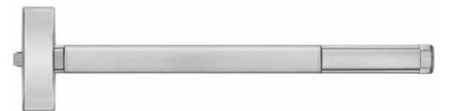
Double Cylinder Kits - Handed
The kit is available to convert 2103, FL2103, 2303 and FL2303 devices to 2110, FL2110, 2310 and FL2310 in the field.
Rim Kit No. RDC10 – Includes locking assembly, cylinder assembly, cylinder collar and active case cover. Two rim type cylinders are required, not furnished standard.
Mortise Kit No. MDC10 – Includes M310 Mortise Lock, extension assembly, cylinder bracket, cylinder collar and active case cover. One rim type and one 1-1/4" long mortise type cylinder required, not furnished standard.
To Order: Specify Hand and Finish (e.g. RDC10 RHRB 630)
Cylinders
Cylinders are not furnished standard with the device or trim. BEST 7 pin standard. Specify Type and finish when ordering. (e.g. 1E74 x 630)
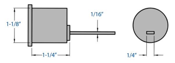
Rim Cylinder - 1E72 x Finish
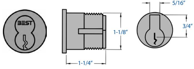
Mortise Cylinder - 1E74-C4 x Finish
Windstorm And Hurricane Code Devices
HC2100 , HC2200, HC2300, HC2800 Series Devices HC822, KRHC822 Mullions
The Hurricane Devices have passed the structural tests as per South Florida Building Code Protocol. These tests are designed to provide sufficient resistance to high wind forces and windborne debris. The devices provide a high level of security for door openings even if hurricane rated door components are not required. A brief description of the test is provided below.
Static Air Pressure Test – Simulates wind loading by evenly distributing air pressure to the face of the door assembly in positive and negative directions. The door assembly must not have excessive deflection or deformation and must remain secure in the chamber.
Missile Impact Test – Simulates impacts created by wind driven debris by impacting the exterior face of the doors with a 2 x 4 board at 50 feet per second. The board must not pass through the doors and the doors must remain secure in the chamber.
Cyclic Wind Pressure Test – Simulates wind gusts by repeating cycles of positive and negative air pressure to determine that the integrity of the door assembly is not compromised with the Missile Impact Test. The door assembly must not have excessive deflection or deformation and must remain secure in the chamber.
Component Approval – These devices are approved as components to be used with any 16 gage Single or a Pair of Hollow Metal Doors and Frames holding a current Notice of Acceptance (NOA). The lowest Design Pressure Rating of the doors or components shall apply.
|
Door Open
ing |
Device
Series |
Design
Pressure |
|
|---|---|---|---|
| Single Door | |||
| Rim Device |
4'-0" W
8'-0" H |
HC2100 | 80 PSF |
|
Surface Vertical
Rod Device |
4'-0" W
8'-0" H |
HC2200 | 80 PSF |
| Mortise Device |
4'-0" W
8'-0" H |
HC2300 | 60 PSF |
|
Concealed Vertical
Rod Device |
4'-0" W
8'-0" H |
HC2800 | 80 PSF |
| Pair Of Doors | |||
|
Two Rim Devices
with Mullion |
8'-0" W
8'-0" H |
HC2100 x
HC822, KRHC822 |
80 PSF |
|
Two Surface
Vertical Rod Device |
8'-0" W
8'-0" H |
HC2200 x
HC2200 |
80 PSF |
|
Mortise Device x
Concealed Vertical Rod Device |
8'-0" W
8'-0" H |
HC2300 x
HC2800 |
60 PSF |
|
Two Concealed
Vertical Rod Device |
8'-0" W
8'-0" H |
HC2800 x
HC2800 |
80 PSF |
Compliance – HC2100, HC2200, HC2300, HC2800 Series Devices and HC822, KRHC822 Mullions comply with the Florida Building Code including the High Velocity Hurricane Zone. The Miami-Dade County Product Control Division has approved these devices to be used in Miami-Dade County and other areas where allowed by the Authority Having Jurisdiction (AHJ). Product Control NOA No. 09-0218.09 is issued for these devices which expires on September 30, 2014.
To see the NOA documentation online:
http://www.miamidade.gov/buildingcode/pc-search_app.asp and type in the NOA number: 05-1102.12 under the Product Search Application link.
| ANSI Function | Device No. | Trim No. | |
|---|---|---|---|
| 01 |
Exit Only
(cover plate) |
HC2101, FLHC2101
HC2201, FLHC2201 HC2301, FLHC2301 HC2801, FLHC2801 |
1701
2001 4901 |
| 02 | Dummy Trim |
HC2102
HC2202 HC2302 HC2802 |
1702A
2002C 4902A |
| 03 |
Key Retracts
Latchbolt |
HC2103, FLHC2103
HC2203, FLHC2203 HC2303, FLHC2303 HC2803, FLHC2803 |
C03
1703 2003 4903 M4903A |
| 05 |
Key Locks /
Unlocks Thumbpiece |
HC2105, FLHC2105
HC2205, FLHC2205 HC2305, FLHC2305 HC2805, FLHC2805 |
1705A
2005A M1705A M2005A |
| 08 |
Key Locks /
Unlocks Lever / Knob |
HC2108, FLHC2108
HC2208, FLHC2208 HC2308, FLHC2308 HC2808, FLHC2808 |
4908A
V4908A M4908A VM4908A |
| 10 |
Double Cylinder
Inside Key Locks / Unlocks Lever / Knob |
HC2110, FLHC2110
HC2310, FLHC2310 |
4910A
V4910A M4910A VM4910A |
| 14 |
No Cylinder
Lever / Knob Always Active |
HC2114, FLHC2114
HC2214, FLHC2214 HC2314, FLHC2314 HC2814, FLHC2814 |
4914A
M4914A |
| 15 |
No Cylinder
Thumbpiece Always Active |
HC2115, FLHC2115
HC2215, FLHC2215 HC2315, FLHC2315 HC2815, FLHC2815 |
1715A
2015C M1715A M2015C |
Trims with the Prefix "M" are for 2300 Series Devices only.
& quot;10" Function is handed.
|
Device Specifications and Options
Rim Exit Devices and Trims4,5 |
Page |
|---|---|
| Surface Vertical Rod Devices and Trims6,7 | |
| Mortise Devices and Trims8,9 | |
| Concealed Vertical Rod Devices and Trims16,17 | |
| HC822 & HCKR822 Mullions18 |
2000 Series Trim not available with 2800 Series Device.

Electric Latch Retraction
Available for all Series Devices
The ELR option provides remote Latch Retraction of exit devices. Continuous duty solenoids retract the Latchbolt(s) for momentary unlatching or continuously for dogging. The ELR feature can be interfaced with automatic door operators, card readers, push buttons, toggle/key switches, and fire alarm systems.
- ELR option REQUIRES ELR150 Series Power Supply.
- UL Listed for Panic and Fire for Class II Circuitry.
- ELR can be used in combination with all Apex options .................... including Hex Key or Cylinder Dogging. ELR option is not available for (DE) Delayed Egress Devices.
Door Widths –
3 Device - 2-7 to 3-0 Door
4 Device - 3-1 to 4-0 Door
The Power Supply model number is determined based on the number of devices requiring electrical power. See To Order ELR150 Power Supply below.
To order: specify prefix "ELR" (e.g. ELR2108)
ELR Conversion Kit
A standard device can be retrofit to the Electric Latch Retraction option by ordering the kits listed below. An ELR Conversion Kit REQUIRES an ELR150 Series Power Supply.
To Order:
Wide Stile Devices
3-0 ELRK-3, ELRKF-3 4-0 ELRK-4, ELRKF-4
Narrow Stile Devices
3-0 NELRK-3, NELRKF-3 4-0 NELRK-4, NELRKF-4
Note: Power may be supplied through a 4-wire continuous circuit hinge (furnished by others).
Solenoid Specifications
Current Pulse (2 seconds max.) ....................... 4.75 Amp.
Continuous ......................................... 3.6 VDC / 0.8 Amp.
To Order: ELR150 Power Supply –
The model number is determined based on the number of devices requiring electrical power.
ELR150 – Power Supply, no control modules
ELR151 – Power Supply including (1) control module to control (1) exit device
ELR152 – Power Supply including (2) control modules to control (2) exit devices
ELR153 – Power Supply including (3) control modules to control (3) exit devices
ELR154 -–Power Supply including (4) control modules to control (4) exit devices
To order power supply with Battery Backup: specify suffix BT (e.g. ELR151BT)
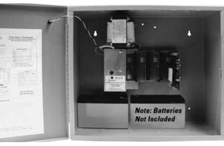
ELR150 Power supply door opened
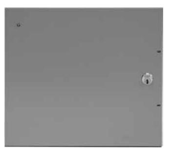
ELR150 Power supply door closed
ELR150 Series Power Supply
The ELR150 Series is a power supply REQUIRED to control ELR Devices. The power supply contains a Motherboard that will accept up to four plug-in Control Modules. Each Control Module (part #CM150-08, see page 22) controls one ELR Device and includes a Time Delay Feature. The Time Delay provides a variable (0 - 4 minutes) Latch Retraction period in response to a momentary input.
Specifications
- UL Listed for Class II Output.
- UL 294 Conforms to U.L. 294 Standards incorporating enhanced Access Control communication capabilities.
- Circuit breakers provide protection for Motherboard.
- 115 or 230 Volt user selectable switch.
- A.C. Input = 115 Volts at 1 Amp.
- Battery Back-up / Power Tap available (see page 22).
- LED Indicator Provides clear indication that power is available to the supply.
- Keyed Cabinet To maintain safety and security, each Power Supply is equipped with a preinstalled key-cylinder.
- Includes lockable box with key lock.
- Dimensions: 16" W x 14" H x 6" D.
- Weight: 15 lbs.
ELR Power Supply Accessories
Control Module
The CM150-08 Control Module is a card that is installed in the ELR150 Series Power Supply and controls one ELR device and includes a Time Delay Feature. The Time Delay provides a variable Latch Retraction period in response to a momentary input.
Specifications Input
Switch Input
• Normally open
Voltage Input
- Input Voltage: 5-24VDC or VAC
- Input Current: approx. 0.005 Amp.
- Minimum pulse width: 0.25 seconds
Output
- Current Pulse: 4.75 Amp. (2 seconds max.)
- Continuous: 3.6 VDC / 0.8 Amp.
Time Delay
• User selectable: 0-4 minutes delay after input is removed
Fire Alarm Terminal
- Red LED (D3) blinks when Fire Alarm interrupts circuit
- Provides immediate termination of output
Switch Input:
• Accepts normally closed contacts or 5-24 Volts from a listed fire detecting device.
Voltage Input:
- Input Current: 0.005 Amp.
- Minimum pulse width: 0.25 seconds
Auxiliary Contacts
- Relay isolated contacts provided for remote signaling (e.g. door operator)
- Normally open or normally closed contacts are rated at 0.5 Amp., 24VDC or VAC
- Contact operation follows successful operation of the ELR device.
To Order: specify CM150-08
Fire Indicator Blinks Red: fire detected, will not accept input ON Red: no fire detected, will accept input Status Light 2 Blinks Green: Independent Mode Double Blinks Green: Sequential Mode On Green: Latches retracted Status Light 1 On Green: input received Mode (CN2-V) Time Delay Jumper Used to activate Time Delay when voltage input received (CN2-SW) Time Delay Jumper Used to activate Time Delay when a switch (dry contact) closure is detected Time Delay Adjustment Allows for outputs to continue for 0 - 4 minutes after input is removed. Note: Time Delay is over ridden when a fire is detected.
(CN1)
Mode Selection Jumper For Sequence Mode or Independent
Power Indicator Green: when power is
present
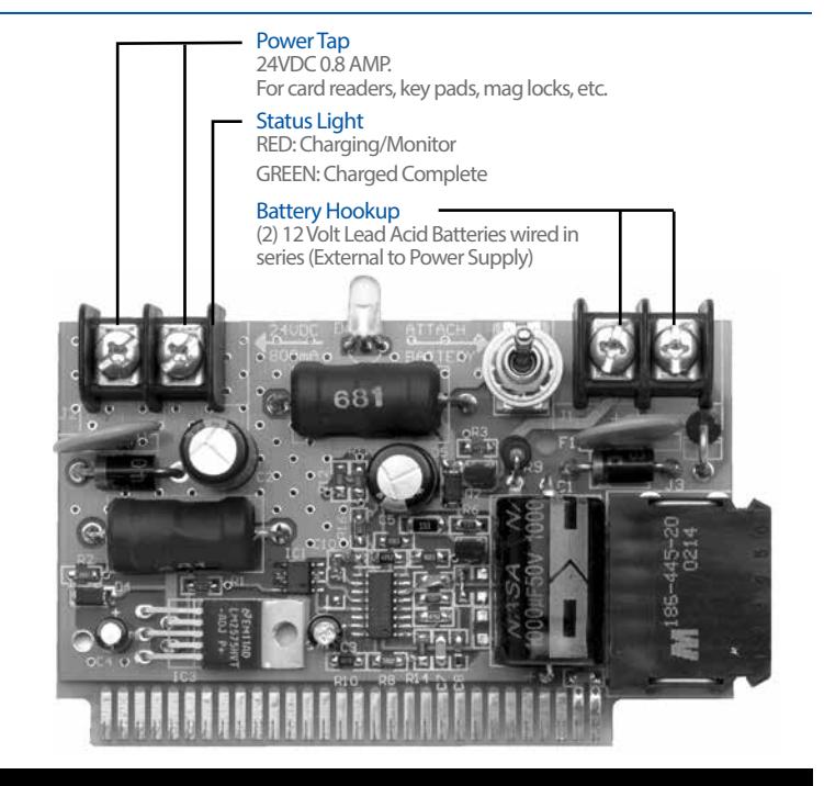
Battery Backup Power Tap
The BT150-07 Battery Backup is an optional card that can be installed in the ELR150 Series Power Supply to provide temporary power to ELR Devices in case of power shortage or outages. Uses (2) 12VDC Lead Acid batteries (furnished by others). One Amp hour set of batteries provides approximately 15 minutes of backup to four exit devices. 24V Power tap is also included to provide power to Card Readers, etc.
Electrical Ratings – 24 VDC, 0.8 Amp. - Power Tap
To Order: specify BT150-07

ELR Application Charts
the Control Module.
Simultaneous Pair of Doors Pressing the push button retracts the latches on each exit device. When both exit devices have retracted latches, the control modules in the power supply signals the door operators to open the doors. The doors will remain open until released by the Time Delay feature on
115 / 230 VAC Battery Backup (Note 4) 115 / 230 VAC Push Button (Note 1) Push Button (Note 1) ELR152 Power Supply Door Operators (Note 2) Exit Device (Note 3) Exit Device (Note 3)
4 Conductor (28 Gage Min.) Power Transfer Required. Ept-5 Concealed Power Transfer (See Page 29), Door Cord Or Hinge (Furnished By Others)
Two Independent Pairs of Doors Each pair of doors are operated by pressing a push button which retracts latch(es) on each exit device. When both exit devices have retracted latches the control modules in the power supply signal the door operators (such as the Precision D-4990 Low Energy Operator) to open the doors. The doors will remain open until released by the Time Delay feature on the Control Module.
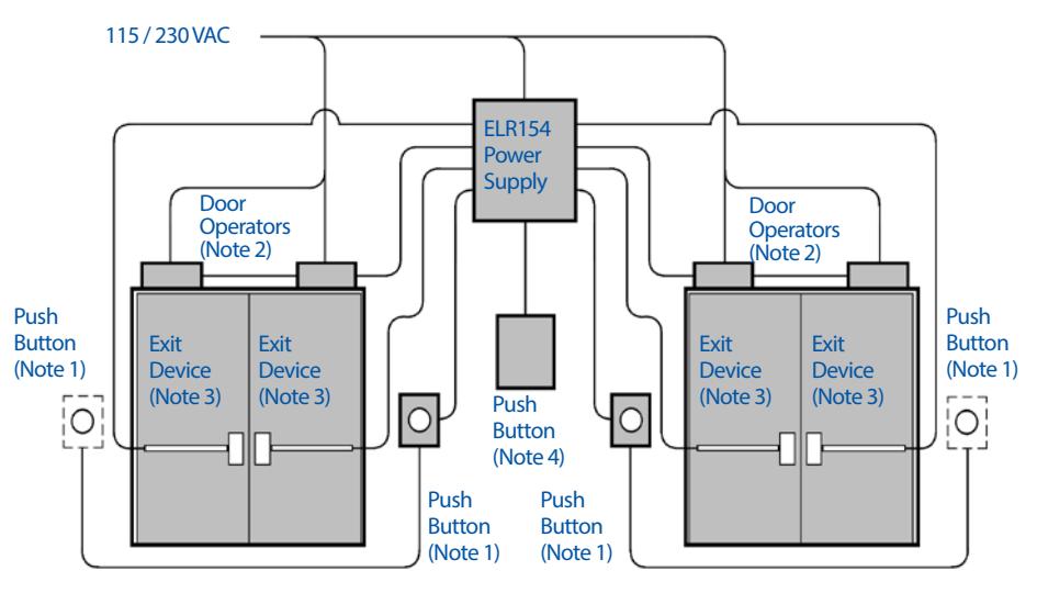
4 Conductor (28 Gage Min.) Power Transfer Required. Ept-5 Concealed Power Transfer (See Page 29), Door Cord Or Hinge (Furnished By Others)
Notes:
- 1. Push Button may be replaced with Card Reader, keypad,etc., providing normally open contacts and/or voltage inputs. See hookup instructions in the ELR150 Installation Instructions.
- 2. Activation for Door Operators are provided by dry contact on the Control Module. (2) wires must be run from the Power Supply to each operator requiring control.
- 3. Each exit device requires (4) wires to operate. See chart to the right for proper gage and wire run.
- 4. When Battery Backup is used, (2) 12 gage wires, less than 3 feet long, connect batteries to Backup. Batteries must be mounted outside the power supply enclosure. Battery Backup has a Power Tap feature that can provide power to a Card Reader, keypad system, etc. See page 22 for details.
| Wire Gage |
Maximum Wire Run
for 22 Gage Power Transfer |
Maximum Wire Run
for 28 Gage Power Transfer |
|---|---|---|
| 16 | 75' – 0" | 55' – 0" |
| 14 | 125' – 0" | 75' – 0" |
| 12 | 200' – 0" |
Delayed Egress
Delayed Egress
The Delayed Egress (DE) Exit Device provides a controlled egress for openings which require Panic or Fire Exit Hardware for safe egress. It is a self contained exit device, which when armed will deny exit to unauthorized personnel for 15 or 30 seconds, while simultaneously sounding a local or remote audible alarm. The Remote Monitoring feature will alert the security personnel that an attempt is being made to exit the opening. After the 15 (or 30) second delay of egress period the device will function as a standard exit device for safe egress.
Operation – The device secures the door in the locked mode with the Red LED indicating locked status. Depressing the Touchbar by accident or for less than the Nuisance Delay Time will sound the alarm without initiating the alarm sequence. Depressing the Touchbar with less than 15 pounds pressure, for longer than the Nuisance Delay Time will initiate an irreversible local audible beeping tone and a visual Red indicator until the device releases. After the delay egress time the lock releases and the alarm changes to a steady tone which continues to alarm until Reset. The remote monitoring contact output can be used to alert security personnel. The person depressing the Touchbar is denied egress (for 15 or 30 seconds) and security personnel are alerted for quick response.
Trim – All standard device trims and functions are available, including "03" function, Trim Lock/Unlock will function normally even when the delayed egress feature is armed. The Device will only be affected when the Touchbar is depressed from the inside. All (DE) Rim and Mortise Devices are also available with Electric Lock/Unlock for the outside Trim. For details see page 28. Available for all Apex Series Exit Devices.
The Delayed Egress Devices are manufactured and tested to exceed ANSI 156.3 and 156.24. Devices are UL Listed as a Controlled Exit Device (FULA) and Special Locking Arrangements (FWAX) category. Meets all requirements of NFPA 101.
Features
Fire Alarm Contacts – Fire Alarm input at any time will cut power to the delayed egress function and provide immediate egress.
Armed-Momentary Egress – Turning the key clockwise allows authorized personnel to exit without alarming. At the end of the field selectable time period (10, 20 or 30 seconds), the device will relock and rearm.
De-Device Networking Feature – This feature allows a Delayed Egress device to arm, alarm, reset and disarm all devices on the same circuit. Each device will continue to operate independently for Momentary Egress.
30 Second Delay – A 30 second delay option is available. A written approval from the authority having jurisdiction is required. Note: A "30 Second" decal is provided when the 30 Second Delay option is specified.
Nuisance Delay Time – A Nuisance Delay Time helps avoid inadvertent activation. The alarm will sound when the touchbar is pressed, but the alarm sequence will not start unless the touch bar is held in for more than the Nuisance Delay Time. Delay Time is field selectable for 0, 1, 2 or 3 seconds.
Integral Key Switch
Arm – The Key switch provides the means to locally arm the (DE) device. Momentary Egress – The Key switch will provide temporary disarming to allow for momentary egress (10, 20 or 30 seconds) when the device
is in the armed state. The Key switch will Disarm the device and it will function as a standard exit device.
Reset – During alarm sequence the device can be rearmed by the Key Switch.
Requires the use of a 1-1/4 mortise cylinder, not furnished standard. Specify when required.
LED Status Indicator (in the device) - A color coded LED indicates Arm, Disarm and Alarm status.
Flashing Green – Arming
Flashing Red – Armed
Green – Unarmed
Red – Alarmed
Off – No Power to Device (Normal Exit)
Internal Alarm – The device has a 85 db horn which will sound until the device is reset.
External Alarm – A set of relay contacts rated at (1 amp, 24VDC) are provided for activating external local or remote audible/visual signaling devices.
External Inhibit
Arm/Rearm – Accepts a contact to Arm/Rearm the device.
Momentary Egress – Accepts a contact to provide temporary disarming to allow for momentary egress when the device is in the armed state. The Momentary Egress will be engaged as long as the switch closure is maintained.
Reset – Accepts a contact to reset the device during alarm.

Delayed Egress (continued)
Door Position Switch – used in conjunction with the Delayed Egress Exit Device, the following security features are added: The Exit Device Alarm will sound if the door is not closed when the device is armed. The Alarm will sound if the door is forced open when the device is armed. While the device is in the arming stage you may exit the opening. When the door closes the arm/rearm time is cut short and the device is armed preventing unauthorized tailgating through the opening.
The PS161-6 Power Supply is designed as a power source for a variety of applications including Electric Locking, Exit Alarm and Delayed Egress Exit Devices.
The Power Supply is a 120V input with a 12 or 24V output rated at 6A. It can control up to 4 delayed egress exit devices. Note: Adding additional loads to the PS161-6 Power Supply (i.e., Card readers, Horns, etc.) may reduce the quantity of Delay Egress Exit Devices controlled by the power supply.
SPECIFICATIONS
Input
- Voltage: 120V AC, 60HZ
- Current: 3.5A AC
- Input fuse ratings: 5A/250V
- AC input is protected via an automatic reset circuit breaker
- Battery fuse ratings: 7.5A/32V
Output
- Voltage: 12 or 24V
- Total output: 6 amps
- Power limit/output: 2 amps/per channel
- Outputs: 8 (For Delayed Egress applications: use only 4)
- Ripple voltage: 910mV (Filtered and regulated outputs)
- Protection: Thermal and short circuit protection with auto reset overload protection.
Battery Backup Charger
- Built-in charger for sealed lead acid or gel type batteries (batteries not included)
- Maximum charge current: 1.54A
- Automatic switch over to stand-by is instantaneous with no interruption
Additional Features
- Short circuit and overload protection.
- Supervised Fire Alarm disconnect (latching or non-latching) on a normally open (NO) or normally closed (NC) trigger.
The (DE) devices are furnished with a decal which states:
Push until alarm sounds. Door can be opened in 15 seconds.
Note: A "30 Second" decal is provided when the 30 Second Delay option is specified.
DE Electrical Specifications
Voltage – 24VDC
Current Disarmed –100 mAmps
Current Armed – 3.2 Amps for 200 ms, 200 mAmps steady state
Door Widths – Available for 3'-0" and 4'-0" openings. For openings 3'-1" and greater, please specify door width requirements.
Note: Not available for openings less than 3'-0"
To Order: specify prefix "DE" (e.g. DEFL2108)

PS161-6 Power Supply (Required for Delayed Egress Devices)
PS161-6 Power Supply
- AC fail supervision (form "C" contacts).
- Unit is complete with power supply, enclosure, battery leads, and lock.
- LED indicators for AC Input, DC output, and battery backup status. Enclosure Dimensions
- 12.5" x 13" x 3.25" (318mm x 330.2mm x 82.55mm)
To Order: specify PS161-6 power supply
Wire Chart And OHMS Law Minimum Wire Gauge for 24 volts AC or DC
|
Distance In Feet From Power Source
To Farthest Locking Device |
|||||
|---|---|---|---|---|---|
| AMPS | 25 | 50 | 75 | 100 | 150 |
| 6.00 | 18 | 16 | 16 | 14 | 12 |
Delayed Egress Application Charts
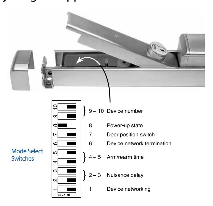
Access Cover Feature – Mode Select Switch panel can be accessed through a hinge stile cover for ease of installation and maintenance without removing the device or Endcap Mounting Bracket. The access cover is secured in place by the device Endcap, which is attached with Security Screws.
Mode Select Switches – The following Mode Select Switch panel (see left) provides field selectable settings to suit the various Delayed Egress applications.
Delayed Egress Application Charts
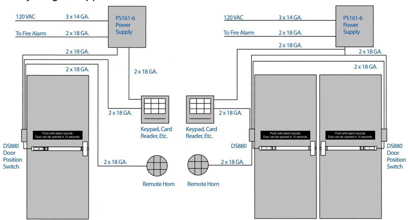
Single Door – This application allows for remote Arm/Disarm and remote monitoring of the Delayed Egress. The Exit device will delay egress when armed and will be a normal exit device when disarmed. The DS880 (DS) Door Position Switch (page 29) prohibits the door from being held or forced open while the device is armed. The 24 VDC, remote switch, remote horn and the DS are routed through the power transfer and the fire alarm is wired to the power supply.
Double Door – This application allows for remote Arm/Disarm and remote monitoring of the Delayed Egress. The Exit device will delay egress when armed and will be a normal exit device when disarmed. The DS880 (DS) Door Position Switch (page 29) prohibits the door from being held or forced open while the device is armed. When one device is alarmed the other device will also go into alarm. The 24 VDC, remote switch, remote horn and the DS are routed through the power transfer and the fire alarm is wired to the power supply.

Exit Alarm
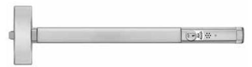
Exit Alarm
Available for all Apex Series Devices
ALK – Battery Operated, provided with a 9 Volt battery and has a audible low battery indicator. Specify WH495 Wire Harness for Remote Arm/Disarm or alternate Input Activation options.
ALW – Remote Powered 12 to 24 VDC at 0.25 Amp., a (2) wire power transfer is required, not furnished standard. Specify WH495 Wire Harness for External Wire features:
- External Arm/Disarm (On/Off)
- External Activation (to sound Alarm)
The Exit Alarm provides a simple way to audibly monitor the use of an exit device. The unit contains a Piezo Alarm which will sound when the touchbar is depressed. Alarm sounds at 80db at 10 feet.
It is also equipped with an LED indicator. The LED flashes GREEN for 20 seconds when the unit is arming and flashes RED every 20 seconds when the alarm is armed.
Note: Latch Bolt Monitoring (LS) or Door Position Switch (DS) is recommended when using Alarm option with 2200 Series Surface Vertical Rod devices.
Cylinder
The Exit Alarm requires a standard 1-1/4 Mortise Cylinder (for cylinder details see page 19) which is used as a key switch to perform the following functions:
- To turn on (Arm) it will allow 20 seconds to exit before ......alarm sounds.
- Silence and reset the alarm after unauthorized egress.
- To turn off (Disarm) the alarm for continuous unmonitored egress.
- Engage mechanical Dogging for Non-Fire Rated Devices.
Wiring Harness - WH495
Can be wired for one or both of the options listed below.
- Exit Alarm can be turned on (Armed) with alternate inputs. For other than our DS880 or NDS986 Door Position Switch a (2) wire power transfer hinge is required (furnished by others).
- Exit alarm can be turned on (Armed) or off (Disarmed) from a remote location. A Cylinder or Dummy Cylinder (by others) is required. Cylinders are not furnished standard. Specify when required (for cylinder details see page 19). A (2) wire power transfer is required, not furnished standard.
To Order: specify WH495
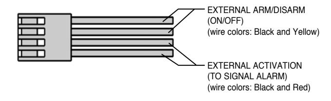
Note: The Exit Alarm is NOT required when ordering the (DE) Delayed Egress option.
Weatherized Exit Alarm
Available for all Apex Series Devices. The Weatherized Exit Alarm is identical in operation to the standard Exit Alarm but incorporates a weatherized design for use on a variety of applications where contact with the elements may occur.
WALW – Remote Powered
12 to 24 VDC at 0.25 Amp., a (2) wire power transfer is required, not furnished standard. Specify WH495 Wire Harness for Remote Arm/ Disarm or alternate Input Activation options.
Weather resistant loss prevention hardware designed for use in outdoor or wet environments:
- Meets the requirements of MIL-STD 810F, Method 506.4, Driving Rain Test (simulating 4 in./hr. rain with 40 mph wind)
- Meets the requirements of MIL-STD 810F, Method 509.4, Salt Fog test (simulating effects of corrosive environments similar to atmospheric conditions found in costal regions)
To Order: Device with Weatherized Exit Alarm – add suffix "WALW" to Device No. (e.g. 2108WALW)
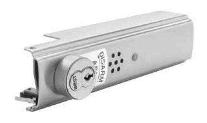
Exit Alarm Kit Available for all Apex Devices from 3-0 to 4-0 wide doors. Furnished with Touchbar decal which states:
The Exit Alarm is available in Kits for Retrofit on existing devices. The channel fillers are different lengths for Narrow and Wide Stile devices. "N" denotes Narrow Stile devices.
To Order: Device with Alarm – add suffix "ALK", "ALW" (e.g. 2108ALK)
Alarm Kits
Wide Stile Devices
2-6 & 3-0 ALK-3, ALW-3 4-0 ALK-4, ALW-4
Narrow Stile Devices
3-0 NALK-3, NALW-3 4-0 NALK-4, NALW-4
- WH495 Wiring Harness Required for External Arming/Disarming the Alarm and External Activation to sound the Alarm.
- Kits are available in finishes 605, 606, 612, 613, 625, 628, .......... 630. For finish description see page 3.
To order: specify Kit No. and finish (e.g. ALK-3 626). Note: For Battery operated kits a 9 Volt battery is included.
Electric Devices
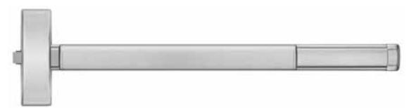
E2103, E2203, E2703 and E2803 Electric Device
Available for 2100, 2200, 2700 and 2800 Series Devices. The Electric Device controls entry by remote locking or unlocking of the outside trim. In addition to a 24 VDC solenoid, the exit device is also equipped with a SPDT - single pole double throw switch. The switch monitors the outside trim (locked or unlocked).
The device is furnished standard as Fail Secure (FSE). When power is off the trim is locked. Power is applied to unlock the trim. May be field converted to the Fail Safe (FS) mode. (FS) - power is applied to lock the trim. Specify (FS) or (FSE) mode when ordering. Specify outside Trim with "08" function. The outside key cylinder retracts the latchbolt for mechanical override. If outside cylinder (mechanical override) is not required, specify outside trim with "14" function.
E2103K Electric Rim Device Kit
To convert 2103, FL2103 devices to E2103, FLE2103 devices in the field. The Kit includes Trim locking assembly and Electric "E" locking assembly.
Note: The exit device can be used as a conduit for wiring to the hinge side of the door.
Electrical Ratings
Switch rated to 2 Amps at 24VDC SPDT
Solenoid current draw: 0.3 Amps.
To Order:
Device: specify prefix "E" (e.g. E2103 FSE 4908A)
Rim Device Kit: specify Kit No. (e.g. E2103K FSE)
Note: "E" locked/unlocked requires "08" or "14" function for outside lever trim.
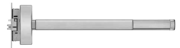
E2303 Electric Mortise Device
The Electric Mortise Device controls entry by remote locking or unlocking of the outside trim. In addition to a 24 VDC solenoid, the mortise lock is also equipped with a SPDT - single pole double throw switch. The switch monitors the outside trim (locked or unlocked).
The device is furnished standard as Fail Secure (FSE). When power is off the trim is locked. Power is applied to unlock the trim. May be field converted to the Fail Safe (FS) mode. (FS) - power is applied to lock the trim. Specify (FS) or (FSE) mode when ordering. Specify outside Trim with "08" function. The outside key cylinder retracts the latchbolt for mechanical override. If outside cylinder (mechanical override) is not required, specify outside trim with "14" function.
Field Conversion
To convert 2303, FL2303 devices to E2303, FLE2303 devices in the field a Electric Mortise Lock is required. Specify EM303, EM303F, LSEM303 or LSEM303F (see below for Electric Mortise Locks).
Electrical Ratings
Switch rated to 2 Amps at 24VDC SPDT
Solenoid current draw: 0.2 Amps.
To Order:
Device: specify prefix "E" (e.g. E2303 FSE M4908A)
Note: "E" locked/unlocked requires "08" or "14" function for outside lever trim.
Electric Mortise Lock - Handed
The Mortise lock is available with the following electrical options:
| MODEL NO. | DESCRIPTION |
|---|---|
| LSM303, LSM303F | latchbolt monitoring, "03" Function |
| LSM308, LSM308F |
latchbolt and trim locked or unlocked
monitoring, "08" Function |
| EM303, EM303F |
electric lock/unlock with switches to
monitor the outside trim (locked or unlocked) |
| LSEM303, LSEM303F |
electric lock/unlock with switches to
monitor the outside trim (locked or unlocked) and to monitor the latchbolt |
Electrical Ratings
Switch rated to 2 Amps at 24VDC SPDT
Solenoid current draw: 0.2 Amps.
Mortise Lock is furnished standard as Fail Secure (FSE). When power is off the trim is locked. Power is applied to unlock the trim. May be field converted to the Fail Safe (FS) mode.
(FS) - power is applied to lock the trim.
To Order: Specify EM303 x (FSE) or (FS) x handing x finish (e.g. EM303 FSE RHRB 630).
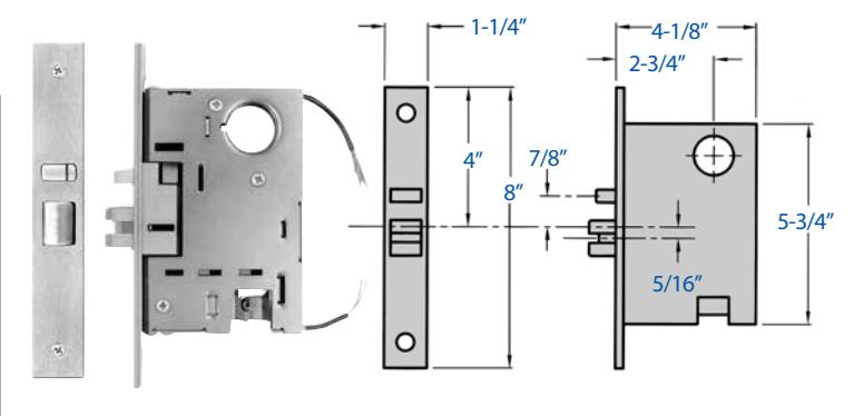
Wiring Diagram
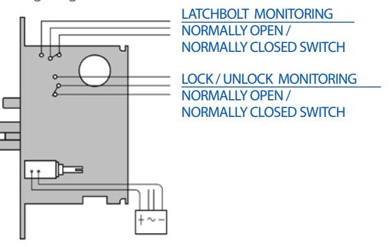

Monitoring Switches
Touchbar Monitoring
Available for all Apex Series Devices. The Touchbar Monitoring Switch is an internally mounted switch that is used to signal electromagnetic locks, horns, monitoring stations or otherelectronic components.
- UL Listed for Panic and Fire for Class II Circuitry.
- TS and TDS can be used in combination with all Apex options including ELR Devices.
TS – (SPDT - Single Pole, Double Throw) version allows for interface with one external component. A (2) wire power transfer is required, not furnished standard.
TDS – (DPDT - Double Pole, Double Throw) version allows for interface with two external components. A (4) wire power transfer is required, not furnished standard.
To Order: specify prefix TS or TDS (e.g. TS2108)
Touchbar Monitoring Conversion Kit
TS and TDS options are available as kits, specify TSK309 for Single Switch Monitoring or TDSK310 for Double Switch Monitoring.
Electrical Ratings
TS – Switch rated to 2 Amps at 24VDC SPDT
TDS – Switch rated to 2 Amps at 24VDC DPDT
Weatherized Touchbar Monitoring
Available for all Apex Series Devices. Weatherized Touchbar Switch WTS/WTDS is designed for use on a variety of exit device applications where contact with the elements may occur. Provided with the same specifications as the standard Touchbar monitoring.
- Meets the requirements of MIL-STD 810F, Method 506.4, Driving Rain Test (simulating 4 in./hr. rain with 40 mph wind)
- Meets the requirements of MIL-STD 810F, Method 509.4, Salt Fog test (simulating effects of corrosive environments similar to atmospheric conditions found in costal regions)
To Order: specify prefix WTS or WTDS (e.g. WTS2108)
Latchbolt Monitoring
Available for Wide Stile Rim, Mortise and Vertical Rod Devices. The Latchbolt Monitoring Switch is an internally mounted switch that monitors the position of the latchbolt.
Mortise LS option monitors auxiliary position. The switch can be used to signal a monitoring station or an alarm such as a Precision ALK/ALW Exit Alarm. For the security of the opening a Door Position Monitoring Switch is recommended.
- UL Listed for Panic and Fire for Class II Circuitry.
- LS and LDS can be used in combination with all Apex options including ELR Devices.
LS – (SPDT - Single Pole, Double Throw) version allows for inter-face with one external component. A (2) wire power transfer is required, not furnished standard.
LDS – (DPDT - Double Pole, Double Throw) version allows for interface with two external components. A (4) wire power transfer is required, not furnished standard.
To Order: specify prefix LS or LDS (e.g. LS2108)
Latchbolt Monitoring Conversion Kit
LS or LDS option is available as a kit for Wide Stile Devices, specify LSRK298 or LDSRK299 for Rim Devices or LSVK910 for Vertical Rod Devices. For Mortise Devices see Electric Mortise Lock, page 28.
Electrical Ratings
LS: Switch rated to 2 Amps at 24VDC SPDT
LDS: Switch rated to 2 Amps at 24VDC DPDT
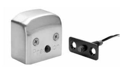
Door Position Monitoring Switch
A Magnetic Reed type switch used to monitor the position of a door from a remote location. It is mounted in the Touchbar Endcap and Door Frame.
Electrical Ratings 1.5 Amps at 24VDC SPDT
To Order:
Wide Stile: specify DS880 and finish.
Narrow Stile: specify NDS986 and finish.
Note: The recommended gap between the magnet and the door position switch when installed is 1/16" - 1/8". Please consider the distance between the exit device end cap and the frame. Depending on your application, the strike, and the template used, the switch and magnet can be adjusted and may extend from the device and/ or frame. Please consult the factory for installation consideration.
Wireless Access Management System
Wireless Activation
The EXQ trim is part of the BEST Wi-Q™ Technology Wireless
Access Management System.
Wireless Access Management System includes:
A) – Precision Q2000 exit device
B) – BEST EXQ trim
C) – WQX–PG portal gateway
D) – BEST Wi-Q™ Technology Software
Note: Items ordered separately.
System Features
- Programmable time selections for desired wireless Lock/Unlock activation
- 65,000 user storage capacity
- Visual LED Indicators
- Redundant storage, up to 99,000 events
- Provides online alarm monitoring capabilities
- Battery powered by 'AA' battery pack
- Access decisions made at the door
- Remote reader diagnostics right from the PC
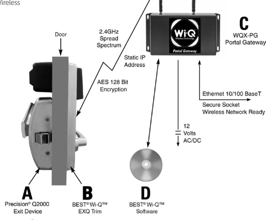
BEST Wi-Q™ Wireless Technology Architecture
A) Precision Q2000 Exit Device
The Precision Q2000 exit device is equipped with the Touchbar Monitor Switch and Latchbolt Monitor Switch features. The integrated Q2000 exit device monitoring switches provide immediate feedback through connectivity with the EXQ trim software to facility security. The Q-option is available for use with Apex wide style, Rim and Vertical Rod exit devices.
Note: Wires routed through active case for EXQ Trim connection.
Note: Q option not available for 2300 series.
Q-Option Retrofit Kits
For existing Apex 2000 Series wide style rim and vertical rod exit devices without the Q-option, retrofit kits are available.
Q-Retrofit Kit includes:
Switch Assemblies, Mounting Hardware and Installation Instructions.
Electrical Ratings – Q-switches rated to 2 Amps at 24VDC SPDT.
To Order:
Q-Option – Specify prefix Q (ex.Q2103)
Q-Retrofit kit
QSRK5267 – 2103 Rim
QSVK5268 – 2203, 2703 Vertical Rod
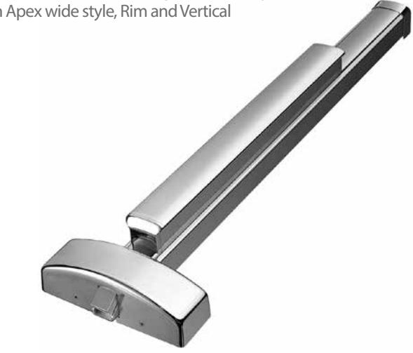
A) Precision™ Q2103 Exit Device

Wireless Access Management System (continued)
B) BEST EXQ Trim
The BEST EXQ Trim provides battery powered online lock/unlock capability for applications utilizing exit device hardware. Used in conjunction with the BEST WQX–PG Portal Gateway and Software, the EXQ trim can receive a wireless command for Lock/Unlock activation. In doing so, the respective facility has immediate efficient pull-side access control for openings that utilize exit device hardware. The EXQ comes standard with a (DS) Door Position Switch. In addition, the trim is equipped with lead wires to integrate the Q2000 Touchbar and Latchbolt Monitoring switches.
The BEST EXQ trim is offered with four different activation styles to choose from. These four types are listed below.
- 1. MS Magnetic Stripe
- 2. DV Dual Validation (Magnetic Stripe + Keypad)
- 3. PH HIDProximity
- 4. PM Indala Proximity
- 5. SC HID iClass
EXQ Trim Features
• Handing (Field reversible)
EXQ Trim Specifications
Materials – Internal parts are brass, zinc, or corrosion treated steel.
Escutcheons – 11.7" H x 3.4" W x 1.2" D.
Door thickness – Standard lock configuration designed for doors 1 3/4" (44mm) – 2 1/4" (57mm) thick.
Lever handle – Brass, bronze, or stainless steel base material. Lever styles 14 and 15 return to a minimum of 1/2" (12mm) of door surface.
Finishes –
- 606 satin brass, clear coated
- 613* oxidized satin bronze, oil rubbed
- 626 satin chromium plated (brass base material)
- 690** dark bronze coated (brass base material)
*613 finish is designed to wear over time, providing an "antique" appearance.
**690 finish will continue as a dark brown appearance over time.
EXQ Trim Exit Device Compatibility
Apex 2000 Series Wide Style Exit Devices:
- Rim device 2103
- Surface vertical rod 2203
- Concealed vertical rod 2703
- Mortise 2303
Note: includes key-override
EXQ Trim Reader Styles
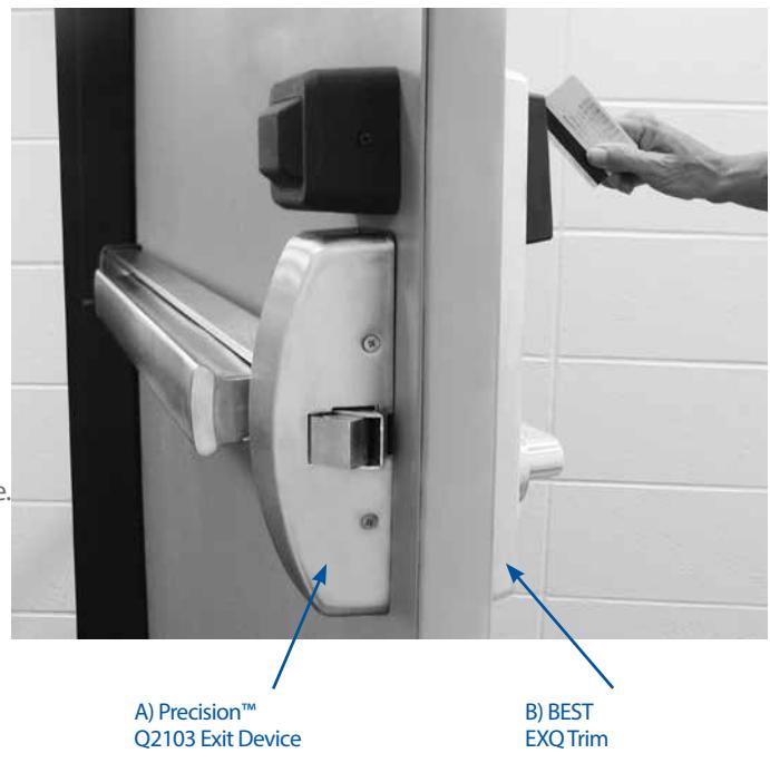


EXQ – Function
With key override Latchbolt operated by: • Outside key • Touchbar Outside lever locked by: signal valid card/PIN
•Outside lever-unless locked by internal motor drive mechanism
• Internal motor drive mechanism operated by time-activated electronic
Outside lever unlocked by:
• Internal motor drive mechanism operated by time-activated electronic signal or by
Inside hardware is always unlocked
For more information on other trims or trim readers refer to: BEST EZ series, Offline Series, and Wireless Access Management catalogs.
Wireless Access Management System (continued)
C) WQX–PG portal gateway
The portal gateway provides a remote integrated solution to BEST's Wi-Q™
Wireless Access Management System. In doing so, all of the crucial components are linked in a secure wireless format providing efficient communication. The following is a list of the Portal Gateway features. For information on how to order, please refer to BEST Wireless Access Management catalog.
Wireless Portal Gateway Features
- Communicates at 2.4GHz spread spectrum to wireless readers or wireless access controllers
- Uses 802.15.4 protocol with clear channels above 802.11 to allow Wi-Fi inter-operability
- 10/100 Base-T bit Ethernet
- Provides redundant communication (locks attach to the strongest signal)
- Non-dedicated portal can communicate with 1 to 128 readers (Does not imply that 128 readers/locks will be within distance of RF range to connect. Total number of portal gateways required is based on individual system survey and requirements.)
- Ceiling mounted omnidirectional antenna included standard when WQX-PG-C is ordered
- Does not require typical controller hardwiring. Simply plug the Portal Gateway into an existing TCP/IP network and provide local power
D) BEST Wi-Q™ Technology Software
The wireless access management software incorporates the functional intelligence for the entire application solution. The net result is a coordinated system with software intelligence found at the control station and remotely as well. Facility personnel can benefit from utilizing the advantages of an integrated software solution found in all aspects of the security and monitoring hardware. For more information or how to order, please refer to BEST's Wireless Access Management catalog.
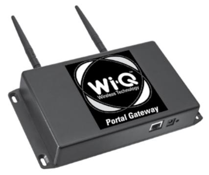
C) WQX-PG Portal Gateway

D) BEST Wi-Q™ Technology Software
Electrical Power Transfer
EPT-5
EPT-5 Power Transfer with stainless steel housing and flexible tube. Secure and inconspicuous channel to bring power from the frame to the door. Narrow, shallow channel easily mortises into frame edges. Accepts up to 5/16" diameter wire bundle. Accommodates doors that swing open 120 degrees. Unit is concealed when the door is closed. Suitable for wood, aluminum or steel application.
- Bright Chrome.
- Holds up to (10) 22 gauge Teflon coated wires. To Order: specify EPT-5.
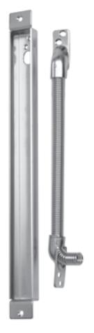
EPT-12C
The EPT-12C provides a pre-installed twelve wire harness for transfer of electric power in a discrete and effective manner.
The harness is equipped with 10 wires @ 24 gauge and
- 2 @ 18 gauge.
- Non-Handed
- Accommodates 180 degree swing
- UL Listed, UL10C
- Stainless Steel Housing & Spring Conduit
- 12 Wire Termination
- Pre-Installed Quick Connect Plugs To Order: specify EPT-12C.
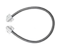
EPT-2 Armored flex conduit. Accepts up to 1/4 diameter wire bundle. Eighteen inches long.


Fire Label Rating
| UL Fire Door Rating | ||||||||
|---|---|---|---|---|---|---|---|---|
|
Type and
Application |
Door
Opening |
Exit Device
Series |
(A)
3 Hour |
(B)
1-1/2 Hour |
(C)
3/4 Hour |
(D)
1-1/2 Hour |
(E)
3/4 Hour |
20
min. Door |
| Single Door | ||||||||
| Rim Device | 4'-0"W x 10'-0"H | FL2100, FL21 | • | • | • | • | • | • |
| Narrow Rim Devices | 4'-0"W x 10'-0"H | FL2400 | • | • | • | • | • | • |
| Mortise Device | 4'-0"W x 10'-0"H | FL2300 | • | • | • | • | • | • |
| Pair Of Doors | ||||||||
|
Two Rim Devices
with Mullion |
8'-0"W x 8'-0"H |
FL2100, FL21 x
FL822, FLKR822 |
• | • | • | • | • | • |
| Two Narrow Rim Devices with Mullion | 8'-0"W x 8'-0"H |
FL2400 x
FL822, FLKR822 |
• | • | • | • | • | • |
|
Two Surface Vertical Rod Devices
Swinging in the Same or Opposite Direction |
8'-0"W x 10'-0"H |
FL2200,
FL2200LBR, FL22, FL22LBR |
• | • | • | • | • | • |
|
Mortise Lock Device x Surface Vertical Rod
Device |
8'-0"W x 10'-0"H |
FL2300 x FL2200,
FL2200LBR, FL22, FL22LBR |
• | • | • | • | • | • |
|
Mortise Lock Device x Concealed Vertical
Rod Device |
8'-0"W x 10'-0"H |
FL2300 x
FL2800, FL2800LBR |
• | • | • | • | • | • |
|
Two Narrow Concealed Vertical Rod
Devices Swinging in the Same or Opposite Direction |
8'-0"W x 10'-0"H |
FL2600,
FL2600LBR |
• | • | • | • | • | • |
|
Two Concealed Vertical Rod Devices
Swinging in the Same or Opposite Direction |
8'-0"W x 10'-0"H |
FL2800,
FL2800LBR |
• | • | • | • | • | • |
| Wood Doors Swinging in the Same Direction | ||||||||
|
Mortise Lock Device
Wood Door Concealed Vertical Rod Device |
8'-0"W x 8'-0"H |
FL2300 x
FL2700 |
• | • | • | • | • | • |
|
Mortise Lock Device Wood Door
Concealed Vertical Less Bottom Rod Device |
8'-0"W x 8'-0"H |
FL2300 x
FL2700LBR |
• | • | • | • | • | • |
| Wood Doors Swinging in the Same or Opposite Direction | ||||||||
|
Two Wood Door Concealed Vertical
Rod Devices |
8'-0"W x 8'-0"H | FL2700 | • | • | • | • | • | • |
|
Two Wood Door
Concealed Vertical Less Bottom Rod Devices |
8'-0"W x 8'-0"H | FL2700LBR | • | • | • | • | • | • |
All Fire Exit Hardware conforms to UL10C and UBC 7-2.
Consult with Door Manufacturer for specific limitations on Fire Door Assemblies.
STRIKES
Rim Exit Devices
For Minimum Stile Widths see pages 36 and 37.
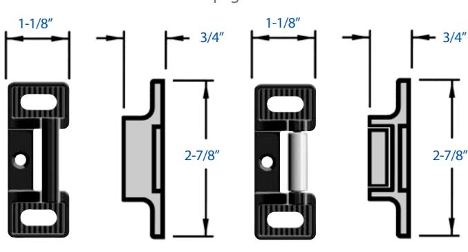
S300 Standard
For Rim and Top Strike for SVR Devices. Specify for FL2400 Devices on Pair of Doors with Mullion. Black Powder Coated Investment Cast Stainless Steel.

For Rim and Top Strike for SVR Devices. Black Powder Coated Investment Cast, Stainless Steel Base and Roller.
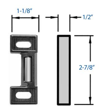
S458 Optional
For Rim Devices. Black Powder Coated Investment Cast, Stainless Steel Base and Roller.
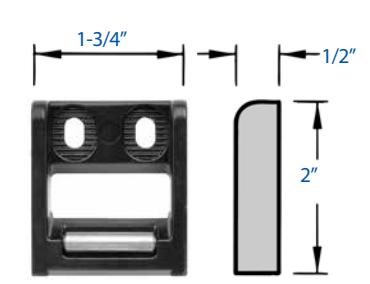
S988 Standard
For Narrow Stile Rim Devices. Black Powder Coated Investment Cast, Stainless Steel Base and Roller. Includes Rub Strip.
Vertical Rod Exit Devices
Top Strike - For Surface Vertical Rod Devices, S300 standard and S301 optional, see above.
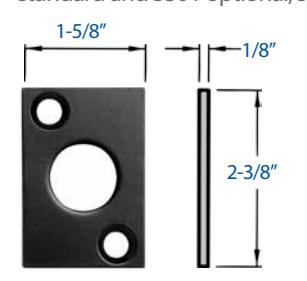
S460 Bottom Strike For Vertical Rod Devices, Surface or Concealed. Black Powder Coated Steel.
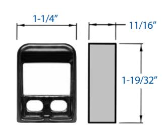
S519 Top Strike
For Concealed Vertical Rod Devices. Black Powder Coated Investment Cast Stainless Steel.
2100 Rim x Vertical Rod Exit Device
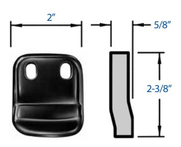
S459 Optional Rim Strike For Non Fire Rated 2100 Rim x Vertical Rod Device on a Pair of Doors without a Mullion.
Black Powder Coated Investment Cast Stainless Steel.
Mortise Exit Devices
Open Back Strikes allow a pair of doors to open and close independently. Strikes are handed. Specify Hand same as Mortise Lock (e.g. RHRB).
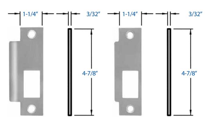
S982 Standard Curved lip.
S983 Optional 7/8" Flat Lip to center. For overlapping astragal.
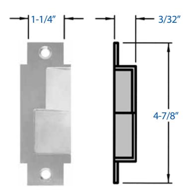
S984 Optional Open Back Strike For 4-7/8" x 1-1/4" door edge cutout.
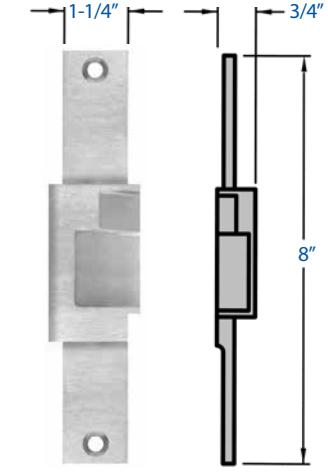
S985 Optional Open Back Strike For 8" x 1-1/4" door edge cutout.
Miscellaneous Components
Dummy Touchbar

Rigid Dummy Touchbar – Touchbar is rigid. For push/pull operation specify Dummy Trim (02 function), see page 5 for Wide Stile and page 11 for Narrow Stile Trims.
3-0 Door 4-0 Door Wide Stile: 671DR-3 671DR-4 Narrow Stile: N673DR-3 N673DR-4
Active Dummy Touchbar with Microswitch – Has an internally mounted switch that is used to signal electromagnetic locks, horns, monitoring stations or other electronic components. For push/pull operation specify Dummy Trim (02 function), see page 5 for Wide Stile and page 11 for Narrow Stile Trims. Available with CD, ALK, ALW, TDS, DS and NDS options.
3-0 Door 4-0 Door Wide Stile: TS672DA-3 TS672DA-4 Narrow Stile: TSN674DA-3 TSN674DA-4 To Order: specify Device No. x finish (e.g. 672DA-3 x 630)
Shim Kit - for Narrow Stile Devices

NSMK995 used to accommodate doors with raised glass moldings. The kit consists of one 1/8" thick shim for the Chassis and one 1/8" thick shim for the End Cap Bracket Assembly.
To Order: Specify NSMK995 (e.g. 2400 NSMK995)
Wide Stile Devices are designed with a 1/4" gap (see page 2) between the back of the touchbar and the door and do not require shims. If more than 1/4" space is needed behind the device specify Shim Kit SMK994.
Braille Touchbar
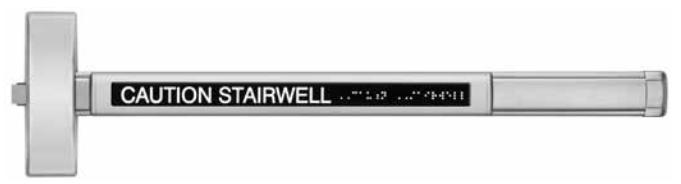
Embossed Touchbar with the message "CAUTION STAIRWELL" in raised letters and Braille provides assistance to persons with impaired vision. Letters are 5/8" high and Braille is Grade 2, ADA compliant. To Order: specify suffix "BRL" (e.g. 2103BRL)
Miscellaneous
Dogging Key DK220 – 7/32 standard hex.
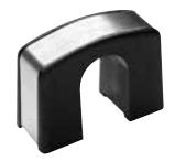
Rod Guide RG124 – For Surface Vertical Rod Devices. Specify finish.
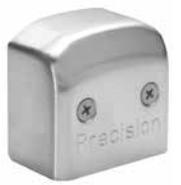
End Cap EC992 – Wide Stile NEC993 – Narrow Stile
For Hinge Stile end of all devices. Specify finish.
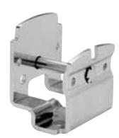
Mounting Bracket MB305 – Wide Stile NMB591 – Narrow Stile
To mount the device to the door on the Hinge Stile side.
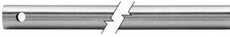
Top Rod – 2200 and FL2200 Series.
Three stock lengths available for 7'-0", 8'-0", and 10'-0" high doors.
TR1854 – For 7'-0" doors, rod is 36" long.
TR1855 – For 8'-0" doors, rod is 48" long.
TR1857 – For 10'-0" doors, rod is 72" long.
TR5197 – For 12'-0" doors, rod is 96" long.
Note: 12'-0" top rod is not available in "FL" fire rated option.
For doors of lesser height rods must be field cut. Specify finish (see page 3 for Finish Descriptions).
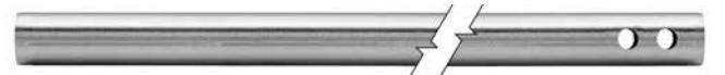
Bottom Rod – 2200 and FL2200 Series.
Extended Bottom Rods – For exit device mounting heights greater than 39 15/16 exteded bottom rods are available.
To Order: B5247-09 x finish.
BR1859 – For Touchbar location at 39-15/16" from finished floor, rod is 32-5/16" long. Specify finish (see page 3 for finish Descriptions).
FB277 – Fire bolt assembly. (See below)
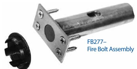
Transom Bracket – 2200 Series. TMB453 – To mount the top strike in the flush transom application. Prepped for S300 Strike.
Strike Hole Plug
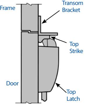
Minimum Stile Width
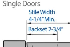
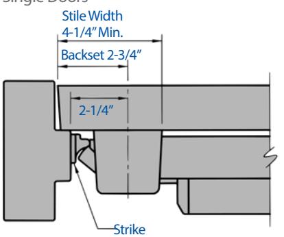
Strike Backset 1-15/16" 2-1/16" Stile Width 3-1/2" Min.
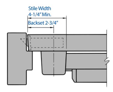
Rim Device with S300 or S301 Strikes
Rim Device with S988 Strikes For 3-1/2" medium stile Aluminum doors and frames. Consult factory.
Mortise Device
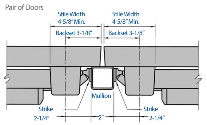
Rim Devices with S300 or S301 Strikes and Mullion
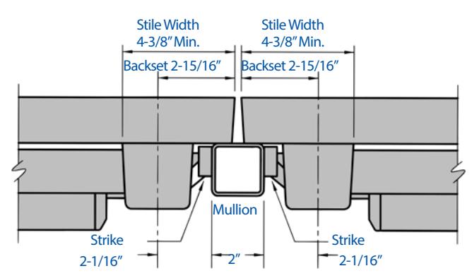
Rim Devices with S458 Strikes and Mullion
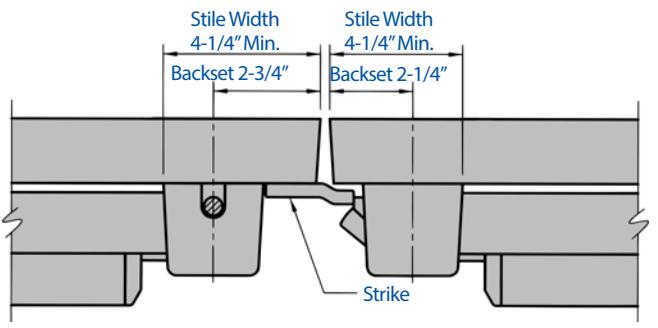
Rim Device and Vertical Rod Device with S459 Strike
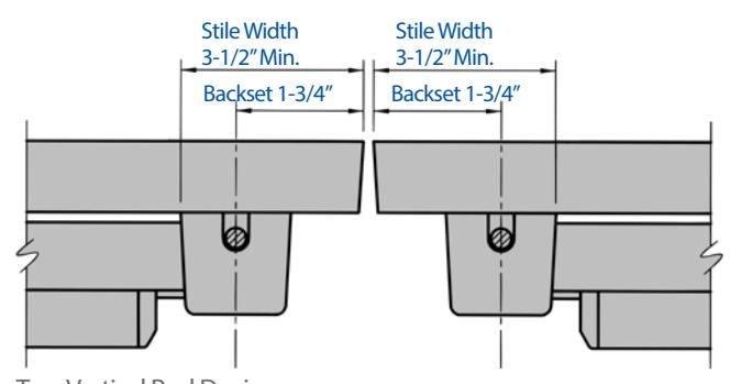
Two Vertical Rod Devices Surface or Concealed
For 3-1/2" medium stile doors consult factory.
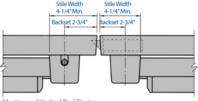
Mortise and Vertical Rod Device Surface or Concealed
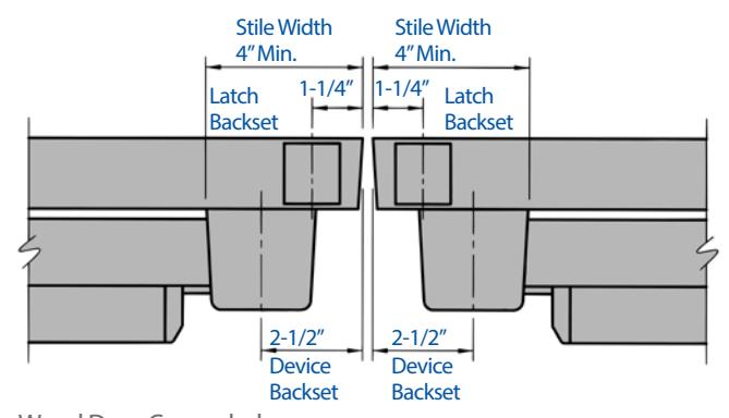
Wood Door Concealed Vertical Rod Devices

Minimum Stile Width
Single Doors – Rim Devices
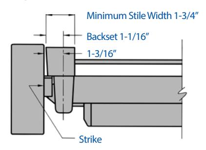
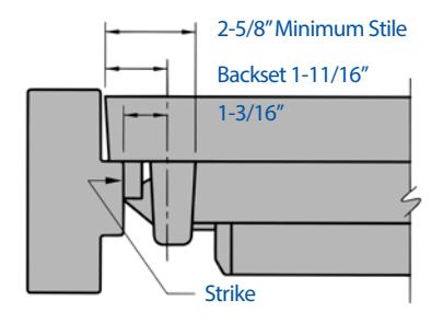
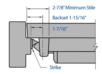
Rim Device with S988 Strike
Rim Device with S458 Strike Rim Device with S300 or S301 Strikes
Pair of Doors – Rim Devices
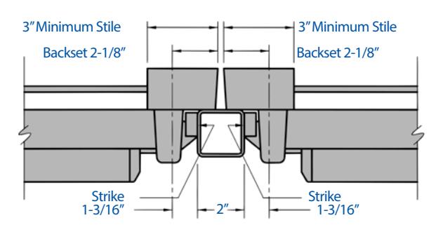
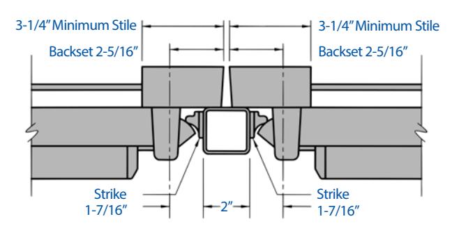
Rim Devices with S458 Strikes and Mullion
Rim Devices with S300 or S301 Strikes and Mullion
Concealed Vertical Rod Devices
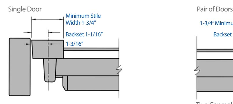
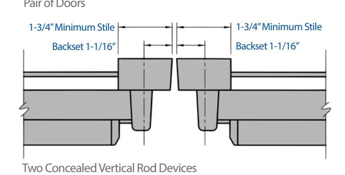
Device Dimensions
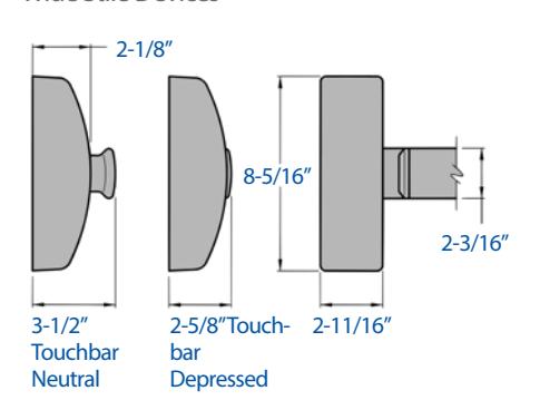
Wide Stile Devices Narrow Stile Devices
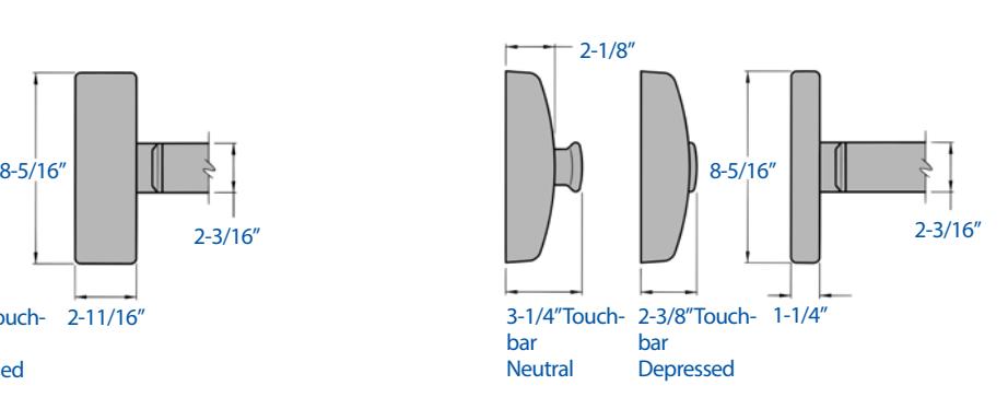
Trim Dimensions
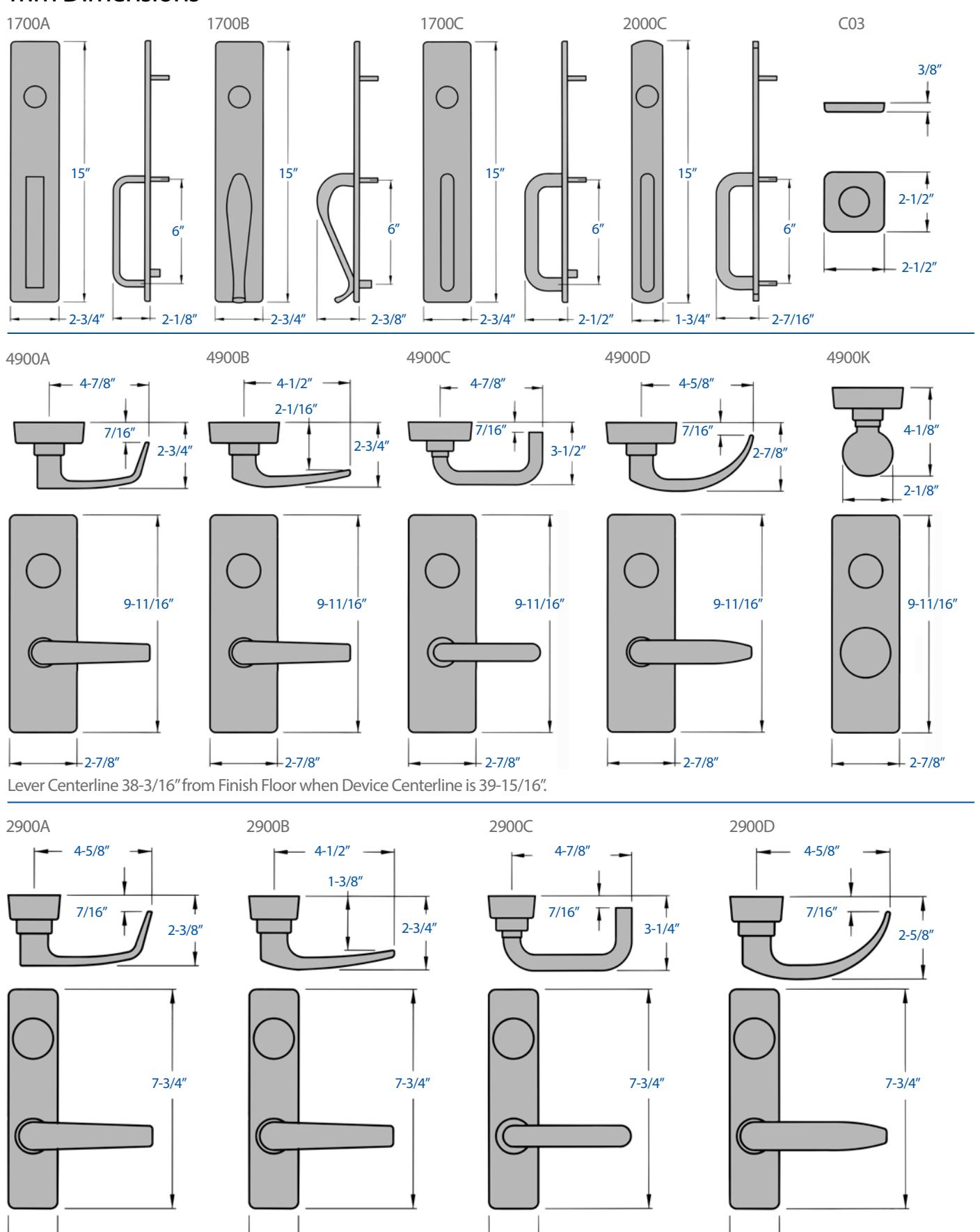
1-3/4"
1-3/4"
Lever Centerline 38-3/16" from Finish Floor when Device Centerline is 39-15/16".
1-3/4"
1-3/4"

Quick Connect Option
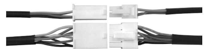
Pre-wired Plug-in Connector
The pre-wired plug-in connectors allow for easy installation to the respective electrical products ordered. When the plug-in connects are ordered, the Precision Hardware Electrified Exit Device ships pre-assembled with the quick connect plugs.
BEST Quick Connect System
BEST Quick Connect plug-in connectors must be used with the following components to work as a complete plug-and-play system:
- 1. Specify appropriate PRECISION or BEST electrified products
- 2. Specify correct wire harness length from door hardware to electric power transfer device or electrified hinge
- 3. Specify either the electric power transfer (EPT-12C) or the electrified hinge (CECB179-12C)
- 4. Specify correct wire harness length from power transfer or electrified hinge to wire extension (WH-6E)
- 5. Choose wire harness extension to connect to power source How To Order
To order the BEST Quick Connect pre-wired plug-in connectors, include the "C" prefix for the Precision Exit Device. See example below.
PRECISION Exit Device
C ELR TS 2108 X V4908A 630
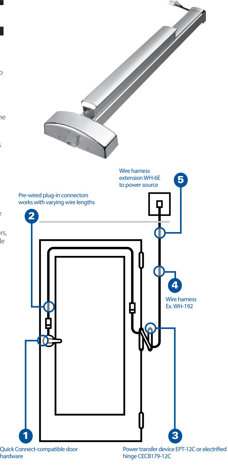
Motorized Latch Retraction
PRECISION Motorized Latch Retraction (MLR) exit devices feature the top-quality materials and robust engineering you expect from PRECISION, while reducing noise, lowering current requirements, and allowing for longer wire runs compared to power hungry solenoiddriven products. Perfect for use in applications that require more flexibility and quieter performance, PRECISION MLR engineering integrates easily with existing security frameworks.
| PRECISION MLR Exit Device Specifications | |
|---|---|
| Certifications |
UL-listed panic and fire
UL 305 UL10C Certified ANSI/BHMA 156.3 Grade 1 FVSU/FVSU7 |
| Power Requirements |
24 Volts DC @ 1 Amp
Holding current 250mA Note: The MLR initial inrush power requirement is 1Amp. @ 24VDC. Other factors must be taken into consideration when selecting a power source, i.e. wire run, wire gauge, other electrical loads, etc. Note: Although PRECISION Power Supplies are not required, RPSMLR2 & RPSMLR2BB Power Supplies are available. |
| Wire Count |
Two brown/white non-polarized power wires
Two blue/yellow non-polarized sensor wires Note: Termination of the sensor wires is optional, but provides positive confirmation of latch retraction when used with the RPSMLR2 or RPSMLR2BB Power Supplies. |
| Opening Width Range |
2'6" Applications: no field cutting; 2'6" openings ONLY
3'0" Applications: no field cutting; 3'0" openings ONLY 4'0" Applications: field cutting permitted down to 3'4" openings |
| Retrofit Kit |
The MLR option can be ordered as a field retrofit kit to accommodate existing APEX 2000 Series exit devices
MLR can be retrofitted to existing ELR exit devices To order the retrofit kit, specify MLR-K Note: MLR is not compatible with certain product options. For example, MLR is not compatible with mechanical dogging. Please consult the factory for additional details. |
| Wire Run |
Maximum wire runs between the power supply and device are as follows:
200 feet with 18 gauge wire 320 feet with 16 gauge wire 500 feet with 14 gauge wire 800 feet with 12 gauge wire |
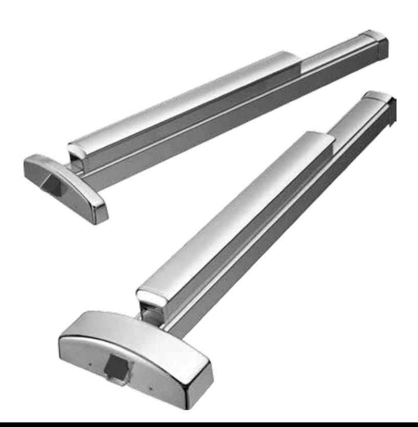

Motorized Latch Retraction
Power Supplies
The PRECISION RPSMLR2 Series is the recommended power source for PRECISION Motorized Latch Retraction (MLR) exit devices. The RPSMLR2 Series provides a code compliant source of filtered and regulated 24 Volt DC power. The RPSMLR2 Series is available in two enclosure sizes and they can each power up to (2) MLR exit devices.
| PRECISION RPSMLR2 Series Power Supplies Standard Specifications | ||||
|---|---|---|---|---|
| Certifications |
UL 294
ULC S-319 |
|||
| Input Power | 120 VAC | |||
| Input | Fire alarm termination | |||
| Output Power |
2 filtered & regulated 24 Volts DC outputs @ 2 Amps
Holding current 200mA 1 filtered & regulated 24 Volts DC auxiliary output @ 0.8 Amps |
|||
| Output |
2 normal open relay outputs
Outputs can be wired for 2 different modes: - 1 second delay prior to relay output - Positive confirmation of latch retraction prior to signaling the operator when used in conjunction with MLR exit device sensor wires |
|||
|
Battery Backup
(RPSMLR2BB only) |
Built in charger for sealed lead acid or gel batteries
Automatically switches to stand-by if AC fails Charging current 650mA max Batteries are not included |
|||
| Visual Indicators |
AC power, green LED – Indicates presence of AC power
Triggered input, 2 red LEDs – Indicates input activation Fire alarm interface, green LED – Indicates fire alarm activation Battery status, red LED – Indicates low battery during AC power failure |
|||
| Enclosure Dimensions |
RPSMLR2: 12.5"x7.5"x3.25"
RPSMLR2BB: 13.5"x13"x3.25" |
|||
| Security | Keyed enclosure | |||
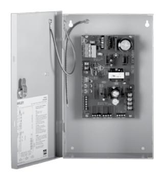

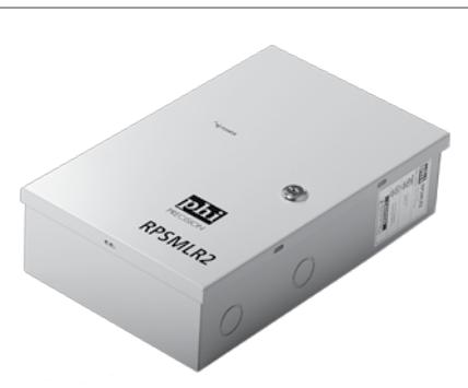
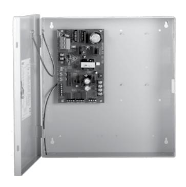
RPSMLR2BB
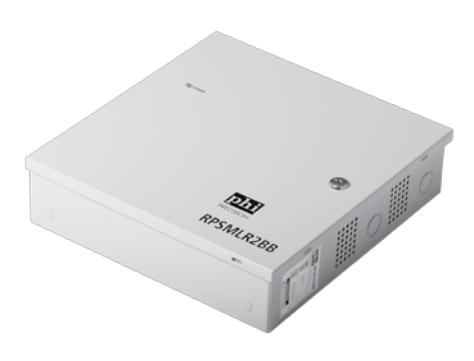

6161 East 75th Street Indianapolis, IN 46250 USA
Phone 855-365-2407
precisionhardware.com